Back to Home
By ACC Corporation
HTML'd for repeater-builder by Kevin Custer W3KKC

|
Up one level (ACC Index) Back to Home |
Repeater and Remote Base Applications of the
FC-1 Frequency Control Board By ACC Corporation HTML'd for repeater-builder by Kevin Custer W3KKC |
|
Introduction
All of ACC's repeater and remote base products support control of synthesized
remote base transceivers. One form of frequency control supported is compatible
with transceivers using thumbwheel frequency selection. The controllers
supply BCD (binary coded decimal) formatted data in a serial bit stream,
which may be captured by external shift registers to drive the transceiver's
frequency synthesizer, simulating the thumbwheel switches.
Applications
The FC-l board may be used with the RC-850, RC-96, and RC-85 Repeater
Controllers, the ITC-32 Intelligent Touch-Tone Control Board and ShackMaster.
It provides the frequency control interface for the ICOM IC-2A/3A/4A (or AT)
transceiver. With minor modifications, it will control certain other BCD format
transceivers (such as the Icom IC-22U). In addition, it can recover expanded
remote control output functions for several of the controllers. The
applications include:
RC-850 Repeater Controller...
Control IC-2/3/4A on Link I or Recover 32 Expanded UF Outputs
RC-85, and RC-96 Repeater Controllers...
Control IC-2/3/4A on Link and Recover 8 Expanded UF Outputs
ITC-32 Intelligent Touch-Tone Control Board...
Control IC-2/3/4A on Link
ShackMaster...
Control IC-2A/3A/4A as a primary or as a secondary transceiver
and Control IC-751 HF rig through its keypad connector
and Recover 8 Expanded Control Outputs
The board is useful for controlling an IC-2A / 3A / 4A (or AT) with
any ACC controller. It may be adapted for the other applications listed above,
but in some cases it may be simpler to duplicate its circuitry or the circuitry
in the controller manual in another format better suited to the application.
Warning: Connection of the FC-1 to the ICOM transceiver
is not a beginner's project.
It requires suitable construction equipment including a temperature
controlled soldering station, and suitable test equipment such as a good
meter or oscilloscope. It also requires relatively advanced construction
and troubleshooting skills and an understanding of digital circuitry. ACC
specifically disclaims responsibility for damage which may result to your
transceiver.
While the FC-1 may be modified to control a variety of BCD controllable transceivers, ACC has direct experience with only certain transceivers, as described in this note. We welcome your input on successful interfaces to other transceivers, and we will make this information available to others on an as-is basis on request. We regret that we can provide technical assistance only for those transceivers with which we have direct experience.
This application note contains the following information:
System Block Diagram
The FC-1 board fits into a repeater or remote base system as shown
below. It is driven by the controller and supplies frequency information
to the BCD controllable transceiver.
The FC-1 board can also provide expanded general purpose remote control outputs when the controller includes this capability as part of the serial bit stream, such as the RC-85 or RC-96 controllers and ShackMaster.
Board Layout and Suggested Enclosure
The layout of the FC-1 board is shown below. Several of the circuits
on the board apply only to ShackMaster and are labeled as they apply to
the ShackMaster application of interfacing to the ICOM IC-751 HF transceiver
keypad connector.
The FC-1 board may be mounted in any way convenient in your installation, but it is designed to fit directly into a Unibox 130 standard enclosure, manufactured by Amerex, PO Box 2815, Riverside, CA 92516, (909) 686-1400. Uniboxes are available from many electronic suppliers. The Unibox enclosure is plastic. It may be preferable to use an RF tight metal enclosure, depending on your installation.
Control of the IC2A / 2AT / 3A / 3AT / 4A / 4AT Transceiver
The ICOM IC2A, IC3A and IC4A transceivers are low cost synthesized hand held rigs
which are easily controllable with external BCD frequency and offset logic signals.
The "T" models are identical except tht they have a built in front panel DTMF
(touchtone) pad.
Enclosure
For applications in high if environments, it may be necessary to mount
the transceiver in an rf tight enclosure, such as a Bud Econobox, for optimum
performance. Signals entering and leaving the enclosure may go through
feedthrough capacitors, as with any high performance repeater rf equipment.
The FC-1 board may mount inside the enclosure with the transceiver to minimize the number of I/O lines requiring feedthrough capacitors. Be careful about degrading the rise times of the clock and data signals from the controller - it may be necessary to reduce the pull-up resistors (R1, R2, and R3) to 1K to restore fast rise times when capacitance is attached to the lines. At low rf sites or where optimum performance isn't required, no special packaging considerations should be necessary.
Interface to Controller
The FC-l board receives the serially encoded frequency and offset information
from the controller, performs the serial-to parallel conversion, and provides
the logic to interface to the transceiver's offset circuitry. The controller
provides serial data and clock (or strobe) as follows:
| Controller | Data | Clock | Transfer |
| RC-850 | UF 7 | UF Strobe | ------ |
| RC-85 or 96 | CX 1 | CX 2 | CX 3 (optional) |
| ITC-32 | OUT 7 | OUT 6 | ------ |
| ShackMaster | DATA | CLK | XFER |
The FC-1 board includes a transfer (XFER) logic input which transfers the outputs of the shift registers to a set of storage registers (inside the 4094 IC's) after the data has been shifted out. The transfer logic input is optionally used with the RC-85, '96, and ShackMaster and prevents "glitches" from appearing at the FC-l expanded remote control outputs. The XFER input is left open (internally pulled up) with the '850 and ITC-32 controllers.
Power Supply
The synthesizer logic inside the IC-2/3/4A transceivers operates from
5 volts, so this dictates the operating voltage of the logic supplying
the control signals. The 5 volt supply for the board may be obtained from
inside the radio.
Interface to Transceiver
BCD Lines - The outputs of the first two shift/store registers drive
the PLL IC inside the radio directly. These are the BCD frequency control
signals developed in response to user commands to the controller. The additional
logic develops the offset signals required on transmit. They connect inside
the radio as described below. The BCD signals may connect directly to the
PLL IC underneath the transceiver's p.c. board. The thumbwheel switches
must be set to all 0 's so they don't short out the signals supplied from
the FC-1.
Offset Signals - The offset switches in the radio may be removed to open the internal paths for the offset signals. Note that the PTT input (described below) must be connected to the controller output driving the radio PTT to activate the offset circuitry. Otherwise, the transmitter will be inhibited.
PTT - The active low open collector PTT signal from the controller should drive the radio through a resistor (around 2.2K) to the base of the switching transistor (IC-2A -Q23; IC-3A - Q23; IC-4A - Q26). Driving the switching transistor directly rather than through the DC path from the PTT switch helps eliminate keying problems when applying audio. Be sure to cut the trace or clip the resistor from the microphone to the base of the keying transistor. This will prevent spurious keying by applied audio.
The PTT signal from the controller driving the transceiver must also connect to the PTT input of the FC-1 board to activate the offset circuitry.
With the RC-85, and '96 controllers in the Glitch-Free mode, the controller's PTT output appears at the FC-l Control Out I (UF8). If not in the Glitch-Free mode, the PTT appears at CX3.
COS - The active high COS signal is available from the audio stage - the audio output amp is powered up only when a signal is received. The switched supply voltage becomes the COS available to the controller at the collector of IC-2A - Q16; IC-3A - Q16; IC-4A - Q17.
Receive Audio to the controller (or to user supplied circuitry in the case of the ITC-32) is easily obtained from the top of the volume control pot in the receiver. The level may be too low to directly drive the RC-850 or RC-85, '96 controllers, but the RC-850 controller input sensitivity can be increased by installing a 4.7K resistor at R87. An acceptable alternative is simply getting speaker audio at the phone jack.
Transmit audio to the IC-2/3/4A should be taken from the RC-850, RC-85,'96, or ShackMaster Transmitter Audio output, or from the repeater receiver in the case of the ITC-32. The audio may be applied through a potentiometer wired as a variable voltage divider for transmit audio level adjustment.
Modifications for Control of the ICOM IC-22U 2M Transceiver
The FC-1 board may be modified slightly to control the IC-22U 2 meter
transceiver. The logic circuitry inside the IC-22U operates at nine volts
rather than the five volt levels of the IC-2/3/4A. Therefore, the FC-1
needs to operate at nine volts as well, requiring a change of two of the
IC's. The offset logic also operates somewhat differently.
The modifications required to operate the FC-1 with the IC-22U transceiver
include:
The FC-1 BCD outputs connect to the IC-22U BCD control lines as shown below:
| FC-1 "PLL IC-1" | IC-22U Connector |
| 10 | J3-5 |
| 9 | J3-6 |
| 8 | J3-7 |
| 7 | J2-1 |
| 6 | J2-2 |
| 5 | J2-3 |
| 4 | J2-4 |
| 3 | J2-5 |
| 14 | --- |
| 13 | --- |
| 12 | J3-3 |
| 11 | J3-4 |
| "- 600" | J1-2 |
| "+ 600" | J1-3 |
Recovering RC85, or RC-96 Controller Expanded UF Outputs
In addition to controlling the IC-2/3/4A transceiver, the FC-1 board
can recover the eight expanded User Function remote control outputs supplied
by the RC-85, or '96 Repeater Controller. To recover the outputs, bypass
the third shift/store register by removing U3 and shorting U3 pin 2 to
pin 9. The eight UF outputs are available as open collector signals at
CONTROL OUTS 8-1 (i.e., UF1 = CONTROL OUT 8, etc.).
| UF1 Control Out 8 | UF5 Control Out 4 |
| UF2 Control Out 7 | UF6 Control Out 3 |
| UF3 Control Out 6 | UF7 Control Out 2 |
| UF4 Control Out 5 | UF8 Control Out 1* |
| * Link PTT in "Glitch Free" Mode |
Recovering RC-850 Controller Expanded UF Outputs
The FC-l Frequency Control Board can recover 32 of the 64 expanded
User Function remote control logic outputs from the RC-850 controller,
although because of the board layout, it may be simpler to build the shift
register circuitry as shown in the '850 Hardware Reference Manual.
The "expanded mode" programming command should be executed on the '850
to inform it of the presence of the FC-1 board. The signals from the '850
to the FC-1 are as follows:
| RC-850 Controller | FC-1 Board |
| UF1 | DATA |
| UF2 | CLK |
| UF3 | XFER |
| GND D | GND |
The board may be operated at any supply voltage ranging from five to
fifteen volts. The operating voltage determines the voltage swing of the
recovered outputs. If operated at other than five volts, ICs U7 and U8
must be removed, since they are five volt devices (the sockets may be left
empty). The logic outputs are available at the following terminals:
| UF Output | Location | Characteristic |
| 1-8 | PLL IC 10-3 | CMOS |
| 9 | On / Off | CMOS |
| 10 | U7 Pin 8 | CMOS |
| 11 | U7 Pin 6 | CMOS |
| 12 | U7 Pin 5 | CMOS |
| 13 - 16 | PLL IC 14 - 11 | CMOS |
| 17 - 22 | Key 0 - 4, Spk | CMOS |
| 23 | U3 Pin 12 (R5) | CMOS |
| 24 | U3 Pin 11 (R4) | CMOS |
| 25 - 32 | Control Outs 1 - 8 | Open Collector |
How It Works
The FC-1 board is simply a set of digital shift registers which perform
a serial-to-parallel conversion of the data stream supplied by the controllers.
In addition, offset logic is included to directly interface to the IC-2/3/4A
transceivers.
Shift Registers
The shift/store registers are 4094B 8-stage shift/store registers with
three-state outputs. They combine an 8-stage shift register with a data
latch for each stage and a three-state output from each latch. Data applied
to the shift register is shifted in on the positive dock transition. Shift
registers are cascaded by applying the output from the last stage of one
register to the data input of the next. The clock signal drives each shift
register in parallel. In the FC-1 board, the logic outputs are kept
continuously enabled by tying the Output Enable pin (15) high.
The signals from the controller include Data, Clock, and optionally, Transfer. When the controller updates the FC-1 board, the information is sent in a rapid burst. The first data entered ends up at the far end (right hand side) of the shift register chain. For each bit, first the data signal is taken high or low, then the clock signal is toggled back and forth to clock the data bit into the shift registers. This process is repeated for each bit in the data stream.
The RC-850 controller clocks out 48 bits from its RB Data and RB Strobe outputs - the last 16 bits are Link/Remote Base 1 frequency information and appear at U1 and U2 for controlling the IC-2/3/4A.
The expanded remote control mode causes 64 bits (UF1 - 64) to be shifted from UF1, UF2, while UF3 serves as a transfer signal (see below). UF1-32 can be captured at U14.
The RC-85, and RC-96 controllers clock out 24 bits - 16 remote base frequency bits appear at U1 and U2 for controlling the IC-2/3/4A, and 8 expanded UF output bits may appear at U4 buffered by U5 (U3 should be bypassed - see "Recovering RC-85 Controller Expanded UF Outputs", below).
The ITC-32 control board clocks out 16 bits when in the serial mode, and again these bits appear at U1 and U2 for controlling the IC-2/3/4A.
ShackMaster clocks out 32 bits, including information for the IC-2/3/4A at U1 and U2, IC-751 control signals at U3, and 8 general purpose remote control outputs appearing at U4 buffered by U5.
After the last bit is clocked out by the controller, a high going transfer pulse may transfer the stabilized data in the shift register to the output latches. In this way, data at the output latches can be kept stable during the shifting process.
If a transfer signal is not supplied by the controller, the FC-1 board holds the transfer inputs of the shift/store registers high so that the shift register outputs always appear at the latch outputs. The result is that while the new data is being shifted in, for a period of about 1 ms, the data at each of the outputs will spuriously change. This isn't a problem for the transceiver, since the disturbance is too short to cause the phase-locked loop to lose lock. It also isn't a problem for any outputs driving relays, since the relay switching time is too long to notice. However, any one-shots or 555s driven by expanded remote control outputs (such as for starting a tape player as an "external device") may be triggered by the "glitches". In this type of application, be sure to use the transfer signal from the controller.
Offset Circuitry
The IC-2A transceiver uses an electronically switched crystal offset
oscillator in conjunction with its frequency synthesizer. One crystal is
used on receive, electronically switched on by R5V (5 volt supply for the
receiver). In transmit, one of three crystals is selected, based on simplex,
duplex-plus, or duplex-minus operation. The logic on the FC-1 board uses
the simplex/duplex and +/- bits from the controller to decide which crystal
to activate. The series diodes isolate the gates from the oscillator when
not selected, and the 47K pull-down resistors provide a bleed path to ground.
The offset signals are needed only during transmit. Therefore, the FC-1 board logic gates in the PTT signal (PTT input to board) to activate the appropriate offset signal only during transmit. The PTT signal must be supplied to the FC-1 offset logic to activate the proper crystal, as well as to the transceiver to key it.
The IC-3A / 3AT and IC-4A / 4AT are interfaced in a similar fashion.
Input Characteristics
The Data, Clock, and Transfer inputs are intended to be driven from
open collector drivers from the controller. Each controller output presents
either an open circuit, in which case the pull-up resistor on the FC-1
determines the logic high state, or the output provides a switch closure
to ground, forcing a logic low state of zero volts.
If it's necessary to bypass these inputs with a capacitor to keep out rf, don't exceed about 100 pF. Decrease the pull-up resistors (R1, R2, and R3) to 1K by paralleling a 1K resistor across the existing 10 Ks.
Output Characteristics
BCD Digits (U1, half of U2). These output bits are supplied from the
4094B CMOS shift/store registers. The logic outputs swing between zero
volts and the supply voltage. They are capable of sourcing and sinking
approximately one mA when operating from a 5 volt supply, or 3 mA when
operating from a 12 volt supply.
Duplex, Simplex, +, -,+5 kHz. These offset signals are supplied by 74HC series logic gates, capable of sourcing and sinking at least 4 mA. Since all the outputs except +5 kHz have a series diode, these outputs only source current. The 47K pull-down resistors provide a DC path to ground for the circuitry in the transceiver. The 74HC08 and 74HC02 supplying these signals must operate from a 5 volt supply. If it is necessary to operate at a different supply voltage, replace these with their 74C equivalents.
Control Outputs. The control logic outputs from the fourth shift/store register (U4) are buffered by a Darlington transistor array. U5, a Sprague ULN2804A, is capable of sinking up to 500 mA at each output in the on state, with a total power dissipation for the package not to exceed 2.25 watts. In the off state, each output can withstand up to 50 volts DC. Being Darlington transistors, when in the on state, the DC output voltage will equal one transistor base-emitter voltage plus one collector - emitter saturation voltage. This means that the low voltage will be .7 volts or higher, depending on the load current. The outputs will not switch to within a couple of tenths of a volt from ground like a single transistor switch.
U/D. The Up/Down output is intended for use only with ShackMaster and is compatible with the ICOM microphone Up/Down input in its transceivers.
Most Often Asked Questions ... and Answers
RC-850 Controller Related...
How can I use two FC-1's on my '850 to control two synthesized remotes?
The two synthesized remotes can be assigned to Link 1 and Link 2 by
simply cascading the two FC-1 boards. To do this, connect one board to
the controller by connecting Data to the controller's RB DATA and Clk to
RB STB (or RB CLK). This first board will respond to Link 1 frequency commands.
Assuming the second board needs to operate at the same supply voltage (because both transceivers operate at the same logic levels), attach its Clk to RB STB as with the first board. Connect its Data to pin 9 of U2 on the first board. This second board will respond to Link 2 frequency commands.
If the boards must operate at different logic levels, such as one at five volts (for an IC-4A, for example), and another at nine volts (for an IC-22U), then the boards can be isolated easily by driving the Data and Clk to the lower supply voltage board through diodes (see below).
How many FC-1 boards are required to recover all 64 user functions from
my '850?
Two. Cascade them by connecting the Data input of the second board
to pin 9 of U4 on the first board. Clk should drive both boards in parallel.
Keep in mind that for this application, it may be more appropriate to build
the shift register circuitry independently as shown in the Hardware Reference
Manual.
RC-85, and RC-96 Controller Related...
Does sharing the phone line tie up any of my remote control outputs
(UF)?
Yes. The Phone Line Busy Out appears at UF3 (Control Out 6), making
it unavailable for general purpose remote control.
If I'm using the RC-85, '96 controller's "glitch-free" mode, where does
the remote base or link PTT appear?
It appears at UF8, which is at the pin labeled Control Out 1.
ShackMaster Related...
Can the same FC-1 that is used for the ICOM IC- 751 control my secondary rig?
Yes, as long as the secondary rig frequency synthesizer operates at
five volts.
How many remote control outputs do I have available with an ICOM IC-751
connected to ShackMaster?
Eight.
General...
The rig that I would like to use isn't on your list of compatible rigs.
What steps should I take to determine whether or not it will interface
and function properly? Understand how the transceiver's frequency synthesizer
is controlled. If it's three digit BCD and the offset looks like it can
be electronically switched, then chances are you should be able to design
the interface logic. The offset signals supplied by the FC-1 board include:
Simplex/Duplex - U2 pin 6. High (+5V etc.) for simplex, low (0V) for
duplex.
Plus/Minus Offset - U2 pin 7. High for plus, low for minus.
5 kHz - U2 pin 5. High for +5 kHz, low for 0 kHz. (This is the one's
kHz digit.)
Can I control two synthesized transceivers from a single FC-1?
Yes, although only one should be activated at a time.
(Exerpt from ACC Notes July / August '86)
Two Remote Bases With Your RC-85, or RC-96 Controller. The RC-850 controller handles four remote bases or links, but the '85, and '96 directly controls only one. However, if you'd like to add a second remote base transceiver to your '85, or '96, such as a ten meter remote in addition to a two meter remote, it's easy,
For the ultimate in simplicity, use a reliable three or four pole relay to switch the control signals between the two transceivers. One of the 85, or '96's remote control outputs can control the relay, by user Touch-Tone command.
If I convert my FC-1 to work with the ICOM IC-22U, are my remote control
outputs (UF) affected in any way?
Not if they're obtained from the Control Output pins. These outputs
are open collector. That is, they look either open circuit or like a contact
closure to ground. Their operation is independent of the board's power
supply voltage.
Schematics and other files
Click here to get a printable schematic of an ACC FC-1:
Horizontal (for viewing)
Vertical (for printing)
Click here to get a schematic of
an ACC FC-1 from WA8DBW (offsite link).
Click here to get a schematic of an Icom
2AT PLL section as printed in the FC-1 manual.
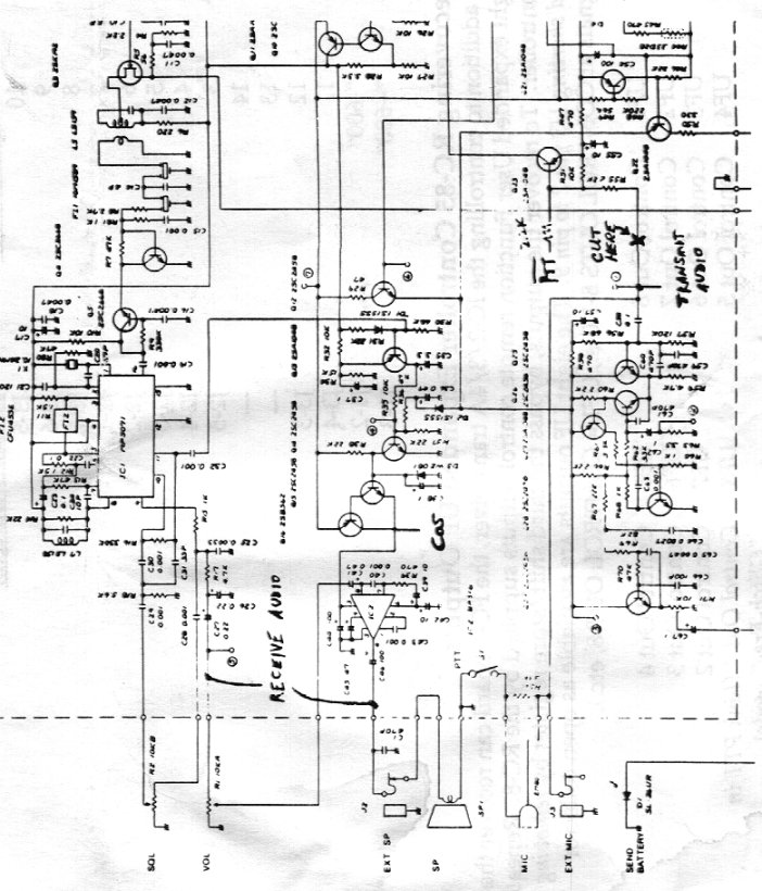
Click here to get a schematic of an
Icom 2AT Audio section as printed in the FC-1 manual.
The full service manuals for the 2AT and 3AT are available from the Icom section
of this web site.
The board layouts and schematics of the PLL section and of the audio section are much
more readable in those files.
Back to the top of the page
Up one level
Back to Home
This page originally posted on 3-Apr-1999 by Kevin Custer W3KKC
Article text, artistic layout and hand-coded HTML © Copyright 3-Apr-1999 by Kevin Custer W3KKC
This web page, this web site, the information presented in and on its pages and in these modifications and conversions is © Copyrighted 1995 and (date of last update) by Kevin Custer W3KKC and multiple originating authors. All Rights Reserved, including that of paper and web publication elsewhere.
The Repeater Builder's site does not evaluate the accuracy of materials created by persons beyond its control or supervision. Therefore, although this site links to many additional web sites, The Repeater Builder's site is not responsible for the availability of or the accuracy of any materials contained within those web sites.