Jeff DePolo WN3A 30 Jan 2000
Introduction
The purpose of this web article is to show how to modify Decibel Products lowband pass cavities to pass/reject. There are several ways to accomplish this. The first edition of this article utilizes a capacitor made out of a section of coaxial cable as a reactance in series with a single cavity loop. At a later date, if the urge strikes, I'll write up another document that describes how to accomplish the same thing using a shunt reactance across a pair of loops, which is a more traditional design. You will probably find that this whole project is very simple, once you've done it. Although this article is pretty long, you should be able to do the whole conversion in about an hour, maybe a little longer the first time.
My usual disclaimer applies with regard to the quality of the images included in this article. The last time I put out a web-based article like this, I got a few comments that the pictures took too long to download. In the interest of time and simplicity, I haven't gone to any extreme measures to compress the files any further, either in terms of JPEG compression ratios or cropping images sizes. But, what I have done is zip up the entire contents so you can download it en masse and not have to wait for individual pieces to appear when viewing it on-line. Also, it will make it easier to keep on hand for when you actually do this conversion yourself.
Also, I'm writing this quickly before the Superbowl starts, so if there are typos or math errors, I apologize, I'll clean them up later.
Sidebar. I'm making an effort to point out some tools and equipment I use. We all know that you can't do a good job without the right tools...
Parts and Tools Required
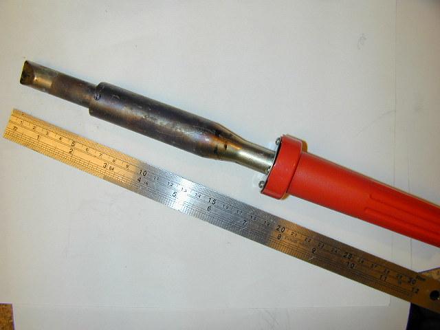
A standard Decibel Products bandpass cavity is 10" in diameter. There are two varieties. The older style is usually painted a tan color and has a rivted-on end cap. The newer style is painted a dark grey and has welded end caps. Aside from those minor differences, they are very similar. The loops are interchangable as well.
For this project, I'm starting out with one of the newer (grey) cavities. Originally it was on 43.xx MHz, but I will be using it in the 6m amateur band. The length of this cavity itself is about 60 inches, not including the tuning rod and bracket at the top. Most Decibel pass/reject cavities that were made for the range 40-50 MHz will tune into the 6m amateur band without a problem, although there will be a LOT of threaded rod exposed, which can be cut off if you desire.
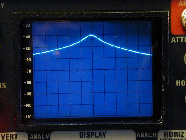
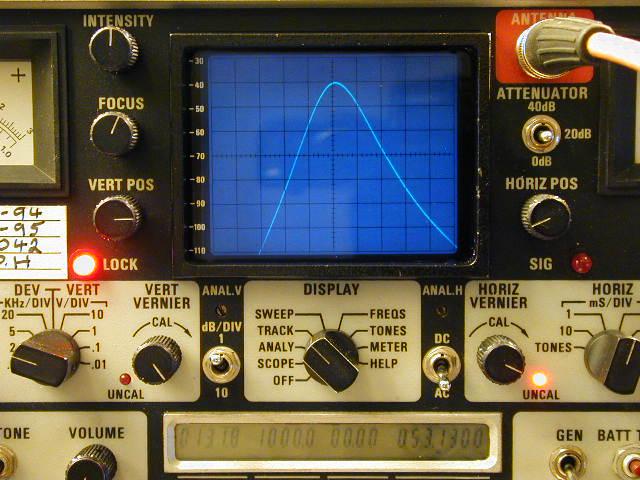
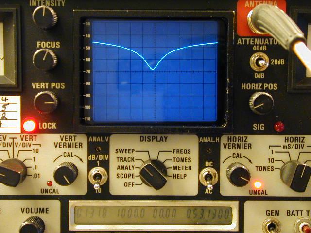
Unmodified, the stock Decibel bandpass cavity has a through response that looks like this:
As you can see, at -1 MHz from the pass frequency, the cavity only yields about 15 dB of attenuation, and at +1 MHz about 18 dB of isolation. Not a whole lot, considering a 6m repeater operating on a 1 MHz split typically requires between 80 and 100 dB of isolation.With the loops set for 0.5 dB insertion loss, the return loss measured was 19 dB with one loop terminated in a good (>60 dB return loss) load. In other words, connected to a perfect load, the stock pass cavity would appear to have a 1.25:1 VSWR. Perfectly acceptable, especially in a lowband installation, but we'll improve on that too.
A wider dispersion view of the response is shown in this image. As you can see, the response is not perfectly symmetrical; there is more attenuation at higher frequencies than lower. This is not uncommon. Before you start on this procedure, pre-tune the cavity somewhere in the neighborhood of where you want your pass frequency to be. It's going to move after we modify the cavity, but just get it in the general vicinity. In the procedure below, I'm going to be tuning for 53.13 MHz pass, 52.13 MHz reject.Step By Step
1. The first thing to do is take the loops out of the cavity. Easy enough to do; just remove the three screws that hold the loop in place and remove.
2. We are only going to need one loop for this design. The hole left by the removal of the second loop should be covered up. There are a few ways to do that, in order of "best engineering" to "real kludge":
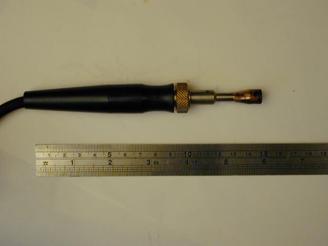
3. Take a look at one of the loops. It is a very simple assembly. The center conductor of the SO239 connects to one end of the loop, and the other end of the loop is connected to the loop disc (ground) via a small metal tab.
- Cut a round disc out of aluminum that is the same size as the existing loop assembly and install it as you would a normal loop assembly.
- Take the extra loop assembly and remove the loop itself, leaving just a connector mounted to the round disc. Install that disc back in the hole; it will have no electrical effect on the cavity with the loop removed.
- Take the extra loop assembly and re-install it upside-down with the loop sticking up in the air and the SO239 connector inside the cavity. Again, it will have no measurable electrical effect on the cavity.
- Cover over the hole with aluminum foil tape
- Cover over the hole with non-conductive tape
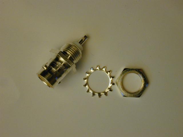
5. Let the loop and plate cool down for a while. A long while. In the meantime, dig through your connector collection and find a single-hole chassis-mount BNC female connector. I'd highly recommend a silver-plated one as it will make soldering a whole lot easier later. We won't be using the lockwasher, just the connector and the nut.
6. What we need to do next is to drill a hole in the loop disc and install the BNC connector. This is probably the trickiest part of the whole operation. There is not a lot of real estate left on the disc. The BNC connector and the clamp nut that holds it in place need to be located such that it doesn't overlap the "lip" area of the cavity when it is inserted, otherwise the assembly will not sit flush in the hole. However, if you install the BNC connector too close to the SO239 connector, the two connectors that attach to the top of the loop (a PL259 and a BNC male) will be too close and you won't be able to get them on.You want to locate the BNC connector on the opposite side of the SO239 from where the ground tab was. This is not really critical as you can rotate the loop around inside the cavity, I just find it aligns better this way once it's installed in the cavity.
If you are a good machinist, you can measure accordingly and determine where the ideal spot is to put the connector. Or if you're a hack machinist like me, place the locknut on the bottom side of the disc, move it as far toward the outer edge as you think you can go without interfering with the cavity lip, then mark and center-punch.7. Drill out the hole for the connector. Most require a 3/8" hole, some a 13/32 hole, some a 7/16 hole. I use a step bit and just keep drilling until it fits, hi.
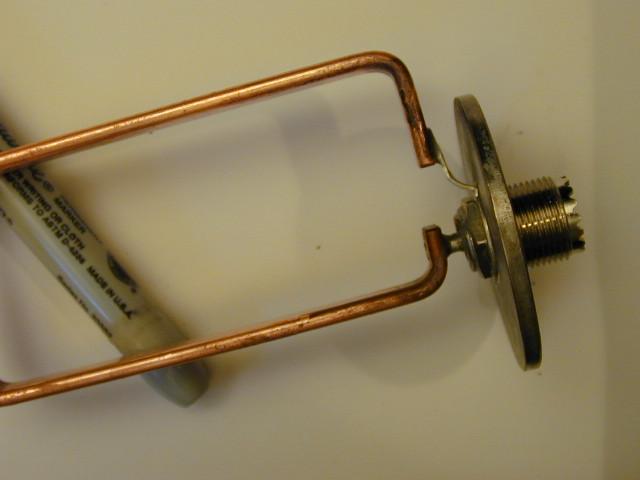
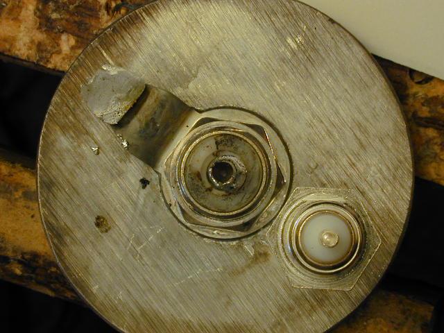
8. Install the connector in the hole using the locknut. Play around with the orientation of the locknut to get a flat side facing the outer edge of the disc to maximize the available space for the edge lip of the cavity. Try installing the assembly in the hole to make sure everything clears. Also, now is your last chance to make sure that you'll be able to get both the PL259 and the BNC male connectors attached to the top, so check that too. Make "minor adjustments" to your drilling as necessary if they won't fit.
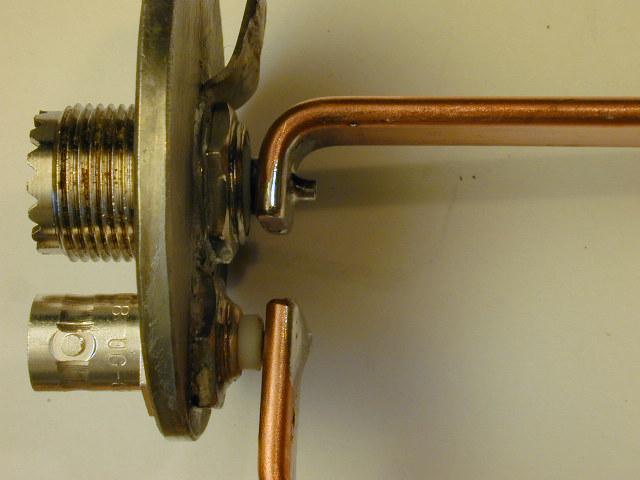
Here's a picture of what it should look like. This one was just a bit tight as far as the distance between the BNC and the SO239 so I had to make some adjustment.
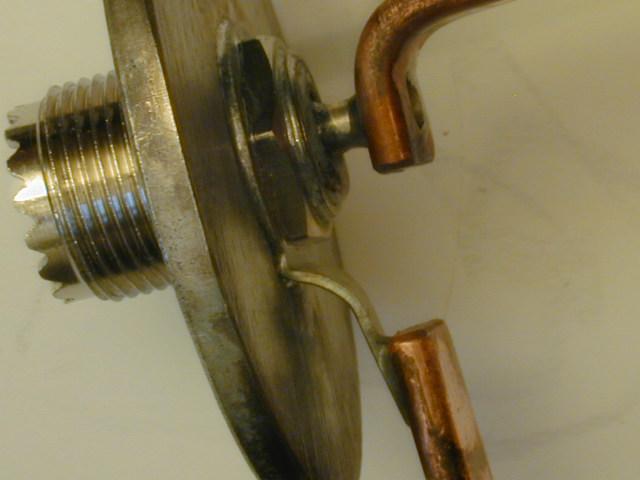
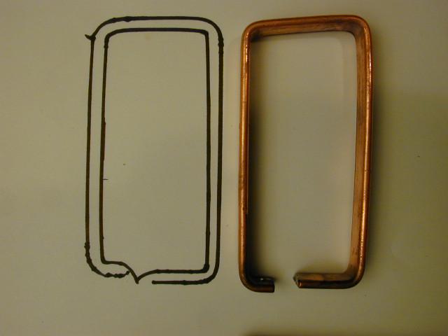
11. Now we need to reinstall the loop. However, instead of one end of the loop being attached to the ground tab, it will be connected to the center pin of the newly-installed BNC. The loop needs to be reformed a bit in order to make everything line up properly. The center pin of the BNC will sit up a little HIGHER from the surface of the disc than will the SO239 center pin. Originally, the ground tab sat LOWER than the S0239. So we're going to shape the loop to compensate. It's one of those things that you just have to do by trial and error, though it isn't too difficult and you don't need any tools, just bend it in your hands. There is a little margin for error here, so you don't have to be too precise. Here's a picture of the before (drawn with a marker) and after effects of reshaping the loop to give you some idea what I'm talking about:
12. Once you think you have the loop properly formed, rough-fit it in place onto the center pin of the SO239. Now you can see where the center pin of the BNC connector is going to line up. Mark that point on the loop and drill it out large enough to accept the BNC's center pin. You can compress/expand the loop as necessary to get everything to line up nice. Once you're happy with how everything is lined up, ensure that the loop isn't sitting too low on either of the connectors and shorting out to the shield portion of the connector. Then, solder the loop/pin connections well, being careful not to use too much solder otherwise you run the risk of having it bead up on the underside of the loop, shorting out the connection.14. Install the UHF tee adapter to the SO239 on the loop assembly. Orient it so that it clears the BNC connector as well as the top bracket on the cavity.
15. Attach a piece of 1/4" Superflex cable with a BNC connector attached on one end to the BNC on the loop assembly. This cable is going to become a coaxial capacitor which will be tuned to set the notch frequency of the cavity. Start out with approximately 3 feet of cable. I'm going to skip the theory for now as to what we're actually doing and just concentrate on the how-to part. At the end of the article will be a link to the theory description.
16. Hook up your spectrum analyzer/tracking generator to the open female ends of the tee adapter. What? You don't have a spectrum analyzer with tracking generator? You're screwed. Seriously, having an SA/TG will make the tuning process go very quickly. It can be done without one, but it's going to require a LOT of patience on your part, and probably a few extra pieces of Superflex because you might end up sacrificing a couple until you get a feel for how the process goes. At the very least you'll need a signal generator and some kind of receiver or detector. I'm going to assume you have an SA/TG here; if you don't, you'll have to work out the equivalent procedure using the equipment you have available.
17. Look at the sweep you have now. You will probably see
something that shows a slight bandpass "peak" and a notch well below the
pass frequency (perhaps up to 10 MHz away). You might even see a
second shallow notch right above the pass peak. That's OK, it's going
to change a whole lot. Tune the cavity plunger to get the pass frequency
in the right place.
<Dang, I forgot to take a picture of that, sorry>
18. Now you're going to start trimming the Superflex cable. As you shorten the cable, two things are going to happen. The notch that is lower in frequency than the pass is going to start moving up in frequency, closer to the pass. Also, a second notch is going to appear above the pass frequency. The more you shorten the cable, the less capacitance it will have. The result is that both notches are going to move up in frequency. In this case, I'm interested in the notch that is lower than the pass, because I want to pass 53.13 and reject 52.13. There will always be two notches in this design, only one of which we're interested in. If you were using this cavity for pass-low/reject high, you'd be concentrating on the upper notch and ignoring the lower one. You get the idea.
At first you can cut off chunks of the Superflex maybe an inch or so long. As you get close, you'll need to cut very small slivers off, on the order of 1/8 inch or smaller. But, before you go crazy with the snippers, take off a few inches to see how the notch moves incrementally when you snip. Also, try rotating the loop. You will see that the pass response changes only slightly, both in terms of frequency as well as loss. However, the notches will move substantially. Rotate the loop to a point about half-way between where the response starts and stops changing as it is being rotated. If you play with it you'll see what I mean here.
19. Incrementally snip of pieces of the Superflex. The tool I'd recommend for this is a Craftsman Robo-snipper. It has a big razor-like blade that makes a nice clean cut without crimping the cable. The center conductor and the shield CANNOT touch, so you have to use a tool that doesn't crimp the cable as its cutting.
20. Stop several hundred kHz shy of getting the notch right on frequency. Loosen up the screws on the loop assembly again and rotate it around. You'll see the notch shift around quite a bit. Adjust the loop so that your notch falls dead on frequency. Verify the pass peak is dead on the money. Iteratively adjust the tuning rod (pass) and the loop orientation (notch) until everything lines up. If it won't line up, take a little more off the Superflex and retune.
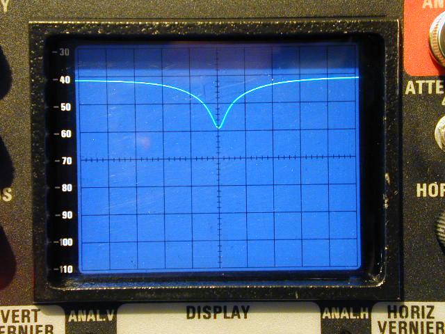
21. If all goes well, you should end up with a picture-perfect pass/notch response. Here's a screen shot of the response I ended up with:
22. Put a piece of heat-shrink tubing over the open end of the Superflex. You definitely don't want anyone touching the open end of it while you're transmitting. Also, I coil up the Superflex and put a few ty-wraps on the loops to keep it out of the way. I measure the capacitance of the resulting Superflex cable with an LCR meter and write it down on the heat shrink for future convenience.
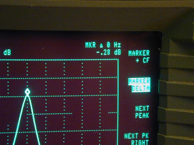
23. Now, measure the return loss at the pass frequency if you have equipment for doing so. If you don't have a return loss bridge, use a transmitter and a Bird and a good dummy load on one side of the tee to check the reflected power. You should find that the peak in the pass response aligns very nicely with the return loss maxima. Here we see that the return loss maxima is about 29 dB, or 10 dB better than the stock cavity was. That's an equivalent VSWR of 1.074:1, very nice. The point of best return loss is just slightly lower in frequency than where we tuned the cavity's pass by about 25 kHz. No big deal. The cavity still gives about 27 dB return loss at 53.13 (the vertical centerline on the display), or a VSWR of 1.094:1. Here's the kicker. Check the insertion loss. I measured this one at 0.28 dB. No kidding, that's it, a little over 1/4 dB. You don't believe me? Maybe you'll believe Mr. Hewlett and Mr. Packard: ConclusionSo, you now should have a 6m pass/reject cavity with well over 20 dB return loss, around 1/4 dB of insertion loss, and 46 dB notch depth. Beat that Celwave. Four cavities like this configured as a duplexer will give right around 100 dB of isolation at under 1 dB of insertion loss per leg. In a future article I will write up how to figure out the interconnect cable lengths to make a duplexer like this.
You can tune this cavity for any pass/reject spacing desired. It will even tune as tight as 200 kHz pass/reject spacing with only slight degradation in insertion loss and return loss, and still yield about 30 dB of notch depth. At 500 kHz spacing, it should do at least 35 dB notch depth, and at 1.7 MHz spacing you should get about 45 dB notch.
I didn't go into detail as to why we're using 1/4" Superflex here. Any type of coax can be used as a capacitor in a circuit like this. Superflex is nice to work with in terms of trimming. The most important consideration is that you want to use cable with the least loss possible. To satisfy my curiosity, I tried using RG58 instead of 1/4" and the notch depth degraded from 46 dB to 30 dB. The lower loss the cable is that you use, the higher the resultant Q of the circuit is, and hence the deeper the notch. So stick with 1/4" flex. I have scraps around if anyone needs a piece. Real 1/4" Superflex connectors are about $10 each. You can use RG8X connectors instead provided they are the right type - email me if you need details on any of that. Because of the mechanical constraints of using a BNC connector, something like 1/2" Heliax wouldn't work as it would require a type N connector (or an adapter, which you want to stay away from at all cost here).
I guess that does it.
Oh yeah, I said I would write up some of the theory part of this project. I will do that later; I want to catch the second half of the game. Do a refresh on this article later in the week and it should show up HERE.
And, no, I don't want to sell any cavities, sorry. But they've been showing up more and more at hamfests over the last several years. Public service agencies are continuing to abandon their old lowband frequencies to move to 800 MHz trunking. Likewise, lowband paging systems have been coming out of service. So, there will continue to be more and more lowband hardware showing up on the used equipment market.
Please let me know if you find this useful. If you have any questions, I'll do my best to answer them. Please send your comments to jeff@depolo.net
HTML Copyright January 2000 Jeff DePolo WN3A and Kevin Custer W3KKC.
All Rights Reserved.