Antenna Index page
Home page
Inter-Cavity Lines
By John Portune W6NBC

|
Book Index page Antenna Index page Home page |
Cavity Duplexers Chapter 9 Inter-Cavity Lines By John Portune W6NBC |
|
This chapter will probably be the most mysterious if you've ever tried to modify a duplexer for a different band. Of all the parts of a duplexer, the lines that connect the cavities and those that connect the duplexer to other devices, generate many questions. They also spawn many old wives tales. Fortunately, we'll learn that determining the length of the lines is actually quite easy, especially if we employ a practical approach.
In this chapter we will look at the types of cable to use and the basic theory what the line lengths between the cavities must be. We'll then explore a practical way to determine those lengths easily. Finally we'll see what to do with the lines that connect the duplexer to the repeater.
Line Type:
Like almost everything else in a duplexers, my experiments demonstrated to me that the type of coax that you use to couple the cavities together is not critical. Only three things matter: The first is shielding. All the coax that you use in a repeater must be 100% shielded. It is basically a necessity. Otherwise all of the effort to isolate your receiver from your transmitter or from the neighbors can easily be lost by direct pickup through the shield of the coax.
Ordinary coax, with a single braided shield, the kind we most often use, is inadequate. It is too leaky. Only two types of coax are satisfactory for repeater use, double-shielded flexible coax or so-called hard line. Most of the common varieties of flexible coax are available in double-shielded versions. The only difference is that they have two layers of either braided wire loom as the outside conductor instead, or one of braid and one of foil. Double-shielded coax is essentially 100% shielded.
Hard line, either rigid or semi-flexible is also totally shielded. Its outer conductor is solid copper or aluminum tubing not braid. Hard line, though, is impractical to use inside a repeater or between the cavities of its duplexer. We normally employ is only for external feed lines. Its main benefit is its ability to withstand weather. Braid-shielded coax with single or double shields over a period of time allows moisture to pass through. This eventually corrupts the dielectric of the coax. Except for a few high-quality coax types, losses increase rapidly in braid-shielded coax exposed to the weather at VHF and UHF. Inside a repeater, though, braid-shielded coax is no problem as long as it is double shielded.
The second factor to consider in the type of cable that you select, is the connectors. Especially for the home builder, this can increase costs considerably. You can find connectors to fit almost any type of cable, but the cost varies dramatically. You won't need many feel of cable to build a duplexer, but you will need quite a few connectors. Shop for connectors carefully.
The exact type that you use is not critical, as long as it is correct for the cable type. I personally prefer crimp-on connectors for convenience and durability, but the tool to attach them does add some expense. The screw-on type are totally satisfactory, however, even if obtained from a local bargain retail electronics outlet.
I recommend two types: N and BNC. If you are running roughly 50 watts or less, BNC is the best choice. They are moderately priced and have good RF characteristics. N connectors are better for higher power and similarly have good RF characteristics. Do not, however, be tempted to use SO/PL 239 connectors above 2M. Even at 2M they are marginal. Such are common on RF devices, but can have poor RF characteristics. One or two in a repeater is not usually a problem, but try to avoid them if you can. Many commercial duplexer manufacturers do use them, but generally they select SO/PL 239 connectors made from special materials. The local radio store variety can cause grief.
The third consideration in selecting cable is power handling capacity. As with connectors, for power levels under roughly 50 watts, double-shielded cable similar in size to common RG-58 is quite satisfactory. I use an economical variety of foil double-shielded RG-58 that is similar to the cable developed for cable TV applications. Most cable manufacturers now offer it. My point is that almost any type will work. If you wish to use the expensive silver-plated double braid varieties, that's fine, but less-expensive types work just as well.
Determining Line Length:
We now come to a very important issue of comprehension for the duplex builder or the home repeater builder wishing to retune a duplexer to another band. It is how we determine how long the lines should be between cavities. It is not common knowledge. And the best part is that it will lead us to a simple practical way to quickly configure the lines between cavities. It will also explain why one cannot simply proportionately rescale the lines for a change of bands.
Here is the concept in a simplified nutshell. We need to make the electrical pathway from one cavity to the next "disappear." In other words, we must "tune" the length of the line until the two cavities think there is no line between them.
To accomplish this perhaps-seemingly difficult feat, we employ a very basic fact about transmission lines, including coax. That is, 1/2 wavelength of transmission line does not change the impedance of what it is connected to it on one end, at the other end. This is of course 1/2 wavelength electrically, not physically. The velocity factor of the line must be factored in.
But because whatever we connect to one end of an electrical 1/2 wavelength of transmission line also appears unchanged at the other end, effectively, as we require, the line does not exist. This simplification ignores losses in the 1/2 wavelength line section, but for the small involved, the losses may be ignored.
So theoretically we need to make the total length of the pathway between the cavities such that the cavities think they are directly connected to each other, essentially with no line in between them. For when we do this, the cavities behave as they should and only then.
But here is something very important. The 1/2 wavelength pathway we need is not made up just of the coax between the cavities. It also partially includes of the coupling loops at both ends to some degree. Notice Figure 9-1. The 1/2 wavelength pathway is roughly the total length shown as the dotted line in the figure, not just the electrical length of the inter-cavity coax.
The full theory is more complex than this, but for the technique we will use to actually constructing the lines, this simplification is quite adequate. The practical procedure we will use, bypasses the theory. I give it merely to help the reader visualize what is going on with inter-cavity lines.
In properly inter-connected adjacent cavities, the total length of the dotted line, Figure 9-1, should appear to be 1/2 wavelength. Notice that the coax is only a part of the total length. The loops must also be included.
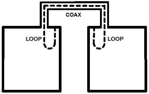
Figure 9-1: An inter-cavity line. Total electrical length = 1/2 wavelength.
Realize then, that if you need to reconfigure a duplexer for another band, the length of the inter-cavity lines is almost impossible to compute. It isn't just a matter of simply rescaling the coax lengths proportional to frequency. This will severely upset the filtering properties of the duplexer. Insertion loss and isolation will suffer.
Instead, the best way I have found to easily determine the correct length for inter-cavity lines is a pragmatic approach. I never attempt a mathematical solution. Actually, the method I use is also used by some commercial duplexer manufacturers.
Make up a set of a dozen cables of the same type of coax and connectors that you'll be using in the final configuration. Make each cable just a little longer in small equal increments. The total set needs to span a full 1/2 electrical wavelength. For example, 1/2 wavelength on 440 MHz is roughly 12 inches. Multiplying this by the velocity factor of the cable I used (0,6), twelve cables in 1 inch increments is a suitable. For 2M, 3 inches increments are fine. Label each cable for easy identification. Make the shortest one roughly 18 in. long for 2M, 6 in. for 440 MHz. Any beginning length is fine as long as it will fit between the cavities.
To use the cable set, begin with either the longest or the shortest cable and connect together two adjacent cavities. Each cavity must have already been individually tuned to frequency. Do not alter cavity tuning during this procedure.
On one side of the pair of cavities connect a spectrum analyzer or your transceiver. On the other side of the pair, connect a though-line wattmeter with a 50 Ohm dummy load or the input of the spectrum analyzer. The lengths of the outboard cables are not critical as long as the source and load impedances of the outboard equipment are truly 50 Ohms.
Now evaluate the cavity pair as described earlier in this book. For the simple setup, collect data points and draw a graph for the cavities in combination. If you have a tracking spectrum analyzer available, it will display the response curve for you. Then simply change to the next cable increment and re- evaluate the cavity pair.
Once you go through the complete set of cables, the correct cable length will be very evident. If two cables seem similar, use either. This is now the cable length that best satisfies a 1/2 wavelength electrical pathway between cavities. Make up a cable of the same length for permanent use.
In essence what you have done pragmatically is to essentially eliminate the inter-cavity line, making the loops think they are in both cavities. At this line length your inter-connected cavities will perform in the complete duplexer without difficulty. They will perform very close to basic cavity theory. Incorrect inter-cavity line lengths cause serious problems.
Then, after you have interconnect all the cavity pairs individually, assemble the complete duplexer and then re-evaluate it as a complete unit in much the same way. Do the input side and output side separately. Just remember to keep any unconnected ports terminated with 50 Ohm dummy loads.
At this point you will be able to estimate the total isolation and the total insertion losses of your complete duplexer from the graphs or the spectrum analyzer display.
External Lines:
You may now be wondering about the lines that connect the duplexer to the receiver, the transmitter and the antenna. Do they also have to be a special length? The simple answer is no, not if you have tuned and configured your duplexer correctly. All external devices should present a 50 Ohm load to the ports of the duplexer, and if as such the lengths of these external lines is not important. Do not tune external lines; it is unnecessary.
There is one exception to tuning an external line - an add-on cavity. Let's say you want to add a pre-amplifier to your repeater. Furthermore you decide that an additional outboard band-pass cavity in front of the preamp would be a good idea.
In this case you also do not need to tune the lines. The preamp isolates the outboard cavity from your duplexer, and presents a 50 Ohm load to each. But if you decide to connect the outboard cavity directly to your duplexer, then you do need to tune the line. For now the external cavity is a working part of your duplexer. Do so in exactly the same way you tuned the inter-cavity lines in the duplexer. Remember, if a line is terminated in 50 Ohm devices, the line does not need to be tuned. A cavity is not a 50 Ohm load, so any line to it needs to be tuned.
Always keep the basic principle in mind for inter-connecting cavities. The total electrical length of the line, including the coupling loops should be 1/2 wavelength. This essentially causes the lines vanish from the picture hence not to change the filtering action of the cavities in any way. That's the objective for inter-cavity lines.
Author's Note:
Well, that's as far as I got. I think, though, that most of it has been said, and in pretty simple terms. So enjoy! Roll your own. You will be pleased.
I will be pleased to correspond: John Portune W6NBC.
jportune [ at ] aol [ dot ] com
w6nbc.com
519 W Taylor St., Unit 111
Santa Maria, CA 93458
January 2019
HTML version for www.repeater-builder.com created by WA1MIK in January 2019.
Contact Information:
The author can be contacted at: jportune [ at ] aol [ dot ] com.
Back to the top of the page
Back to Book Index page
Back to Antenna Index page
Back to Home
This article created on Wednesday 09-Jan-2019.
Article text, images and photographs © Copyright 2019 by John Portune W6NBC.
Layout and conversion to HTML © Copyright 2019 by Robert W. Meister WA1MIK.
This web page, this web site, the information presented in and on its pages and in these modifications and conversions is © Copyrighted 1995 and (date of last update) by Kevin Custer W3KKC and multiple originating authors. All Rights Reserved, including that of paper and web publication elsewhere.