Back to Home
Controller Improvements
By Matt Krick K3MK
FluX Research
|
Up to Arcom index Back to Home |
Arcom Repeater Controller Improvements By Matt Krick K3MK FluX Research |
|
Models Affected: Arcom RC210 and RC810.
Serial numbers affected: All to date.
Problem or Symptom:
Poor quality tone generation and filtering affects the signal-to-noise ratio of courtesy tones, DTMF and CW signals.
Background:
The Arcom repeater controllers use Pulse Width Modulation to generate the various tone frequencies. The PWM carrier or sampling rate is typically around 32 kHz.
The Science Behind it:
Please refer to US patent #6,671,315.
PWM Sine Table:
To save flash programming space, the controllers use a 32 sample sine wave table. This only allows a theoretical maximum of a 27dB signal-to-noise ratio. The SNR can be improved by enlarging the sine table; doubling the size of the sine table increases the SNR 6dB. 128 samples will yield a 39dB SNR. This can be remedied with a software update should Arcom choose to release one.
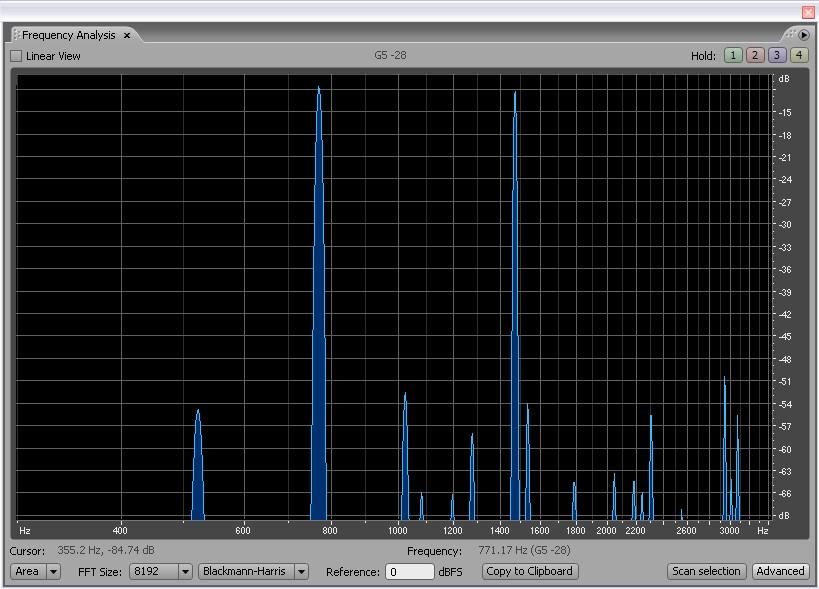
Spectrum Analysis of 128 sample DTMF '6' at approx. 39dB SNR
Tone Synchronization:
At the end of a tone, the sine wave table pointers should be set back to zero. This modification allows two frequencies spaced 1 Hz apart to 'throb' like in the Advanced Computer Controls RC-850.
The sine table should also begin at the DC zero point of the sine wave, typically '63'. This reduces popping between CW tones.
When the tone is completed the PWM ratio should be set to 50%, keeping the carrier alive to avoid any DC bias problems and popping at the beginning of the tones. This can be remedied with a software update should Arcom choose to release one.
Low Pass Filter:
The PWM pin of the microcontroller is followed by a simple R/C filter consisting of a 10k resistor and a 0.1uF capacitor. This combination creates a corner frequency of 159.2 Hz.
Stock Low Pass Filter Frequency Response
Everything that is above 500 Hz (Corner Frequency * Pi) gets attenuated approximately 6dB per octave. This amount of 'twist' is unacceptable in a DTMF telephony system as the specifications only allow for 3dB maximum as well as for the higher frequency tone to be the one in higher amplitude.
PWM Frequency:
Because the PWM frequency is only 20dB attenuated from the maximum tone frequency, it is possible for the 32 kHz to get into the audio chain of the transmitter and generate side bands ±32 kHz from the center of the channel. This has the potential to create interference on standard band plan 30 kHz spacing VHF, second adjacent 15 kHz VHF 'narrower band' channels, as well as 25 kHz spacing UHF channels. This should only affect directly modulated transmitters with no frequency limiting 'splatter filter' circuitry on the audio input, but leakage may be present in other models.
Improved Low Pass Filter:
By employing a 3-pole Sallen-Key Op-Amp filter, it is possible to maintain a 0 to 3 kHz pass band with 0.8dB of ripple and get 60dB attenuation at the carrier frequency.
Improved Low Pass Filter Schematic
This filter will increase the total usable volume of the tone, reduce 'twist' to tolerable levels and reduce the amount of PWM carrier transmitted. The parts list is 'Radio Hut' friendly and can be built without having to play the mail order game.
Improved Low Pass Filter Installation RC210 Revision 3.0a:
Please refer to the Arcom RC210 Revision 3.0a Hardware Manual for the RC2103_0 schematic. Different revisions may have different part designations; plan accordingly.
Piggy back the power from the controller. R63 will source +12V and the R63 / R62 junction will source Vpp. Obtain ground from the low side of R62.
Remove R65 and C47 from the controller. Connect the controller's 'Tone' to the improved low pass filter '32 kHz PWM Input' and 'Audio Output' of the filter to the high side of R68. R65's mounting holes may be used for audio send and return for the filter.
Improved Low Pass Filter Installation RC810:
Please refer to the Arcom RC810 Hardware Manual for the RC810_radiocard4_5 schematic.
Piggy back the power from the radio card. The R4 / R24 junction will source +12 and the R24 / R27 junction will source Vpp. Obtain ground from the low side of R27.
Remove R21 and C19 from the individual radio card. Connect the card's 'Tone' to the improved low pass filter '32 kHz PWM Input' and 'Audio Output' of the filter to the high side of R39. R21's mounting holes may be used for audio send and return for the filter.
Acknowledgements and Credits:
This article originated as FLuX Research Technical Service Bulletin FXR-03, release date Date: 11-Jun-2007.
Schematics by: Matt Krick, K3MK drawn with ExpressSCH by ExpressPCB.
Frequency plots by: Matt Krick, K3MK plotted with Elsie by Tonne Software.
Spectrum Analysis plots by: Matt Krick, K3MK plotted with Adobe Audition.
'Arcom' refers to Arcom Communications, 24035 NE Butteville Rd., Aurora, OR 97002, 503-678-6182.
Legal notice - All the material in this technical service bulletin is Copyright 2007 Matt Krick, K3MK. All Rights Reserved.
The author takes no responsibility for any damage during the modification or for any wrong information made on this modification. Your results may vary.
Commercial use of this bulletin is not authorized without express written permission of the author.
Furthermore, this work is specifically prohibited from being posted to www.mods.dk or any other 'limited free site'. Please ask for permission before posting elsewhere.
Contact Information:
The author can be contacted at DCFluX [ at ] yahoo [ dot ] com.
Back to the top of the page
Up to Arcom index
Back to Home
This page originally posted on Saturday 19-Jul-2008
Article text, images, drawings, and artistic layout © Copyright 2008 by Matt Krick K3MK.
Conversion to HTML by Robert Meister WA1MIK.
This web page, this web site, the information presented in and on its pages and in these modifications and conversions is © Copyrighted 1995 and (date of last update) by Kevin Custer W3KKC and multiple originating authors. All Rights Reserved, including that of paper and web publication elsewhere.