Back to Home
Repeater Audio Delay Unit
By Robert W. Meister WA1MIK

|
Up one level Back to Home |
Evaluation of the Arcom RAD Repeater Audio Delay Unit By Robert W. Meister WA1MIK |
|
Product Details (from the Arcom web site):
"Our RAD uses the latest state-of-the-art Codec IC. All versions of our RAD offer all-digital high performance operation. By using the RAD, you can eliminate squelch bursts when users un-key their radios and also completely mute all DTMF tones. It provides gated audio to allow the RAD to properly deal with non-gated audio from your receiver(s). This eliminates problems common in other designs and can provide from 6 milliseconds to over 600 milliseconds of delay, selectable by easy trim-pot adjustment. Our new design incorporates one PC Board for all three versions (one port, two port, or three port). This reduces the amount of space needed in our RC210R Rack Mount Enclosure to allow for more available room."
The RAD is apparently intended for use with an Arcom RC210 three-port repeater controller. There are very few actual posted specs.
RC210 and RAD are model numbers used by Arcom Communications.
Ordering Experience:
This was my first purchase from Arcom. I sent an email on December 3rd 2019 to their sales department asking the following questions:
Ken Arck replied almost immediately with "Sure we can build one that way" and "Active low and +5V is fine". He told me how to purchase the unit and enter the order with my specific requirements, which I did shortly afterward. Payment was via my credit card. I received a shipping notice on December 5th and received the unit on December 9th.
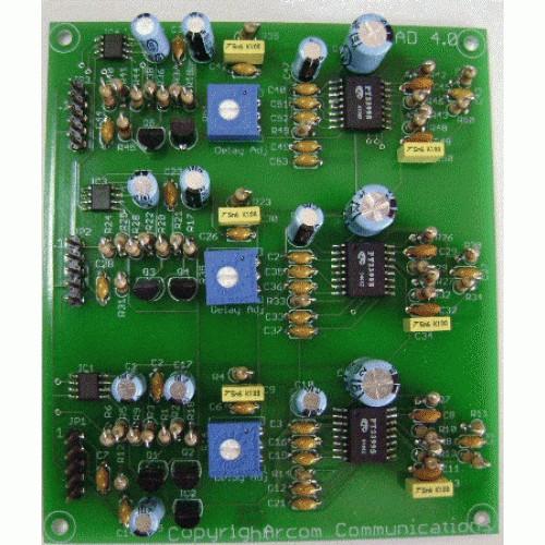
The photo below, from the Arcom web site, is of the triple delay unit RAD3. I wanted the single delay unit RAD1 with the lowest section populated. Normally they populate the top-most section for the RAD1 or the top and middle sections for the RAD2.
The photo below (click on any image for a larger view) shows the unit as I received it from Arcom. As requested, the lowest unit was installed. Notice that there is a cable with a 5-pin female connector soldered to the board where I had expected a 5-pin male header, as shown above.
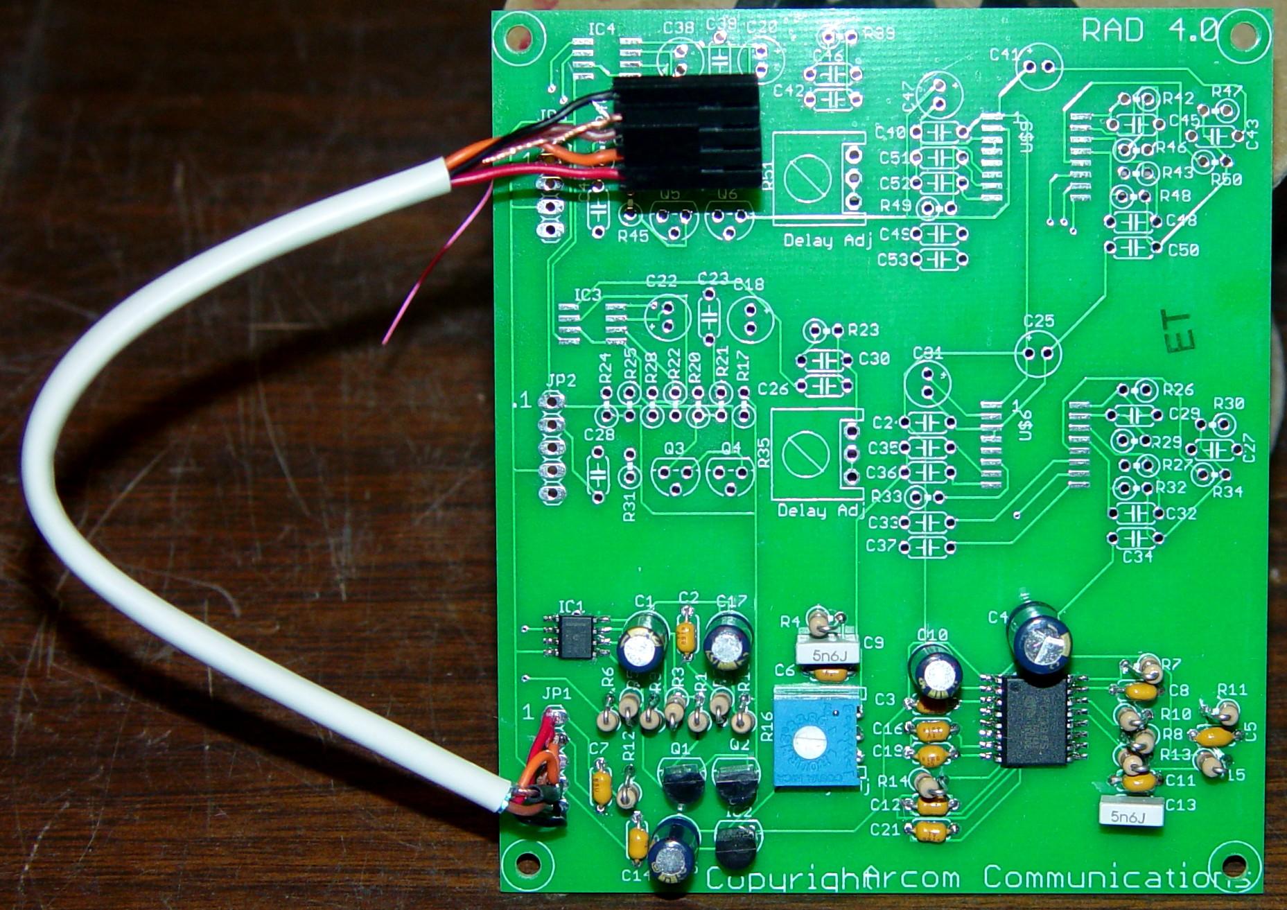
When I questioned this configuration, Ken responded: "We build for the RC210 and you never mentioned anything other than populating the part of the board we did." I was expecting the board to look like it did in their photos, with a 5-pin male header. Also my original email questions stated I wanted to use the board by itself, not with an RC210. I was not given a choice as to the connector configuration when I ordered or when I previously communicated with Ken, so I just figured I'd get a unit as it was shown in their photos. Ken did offer to send me a 5-pin male header and other connector parts to fashion my own cable. The parts themselves are under $1 but it hurts to have to pay $5 to ship them, when the board should have been built as it was shown on their web page. As Katherine Hepburn said on the movie "Desk Set": "Never assume."
Ultimately I decided to return the unit, as it did not meet my needs. I filled out their RMA form but never got an RMA. It turns out no RMA is needed unless you're upgrading firmware on one of their controllers.
Bench Testing the Unit:
Build quality appeared to be excellent however the board had obviously been hand-soldered and there was no attempt to remove the flux residue from the bottom of the board. Despite the three independent circuits on the board, there were interconnections between the sections for more than just the +5V signal.
I stuffed five low-value resistors into the female connector (to give me someplace to connect clip leads) and attached the unit to a variable DC power supply and my distortion analyzer, which contains a low-distortion audio oscillator, a true-RMS voltmeter, and a distortion meter. I determined that an audio level of +1dBm (0.87Vrms) was about the maximum the unit could pass without creating any distortion at 1 kHz, so I ran my tests at 0dBm (0.775Vrms). I specifically measured the frequency response from 20 Hz to 10 kHz, the distortion at selected frequencies and input levels, and the audio attenuation when the COS input is at +5V. I also varied the incoming DC voltage to see what effect that had and to determine the minimum acceptable supply voltage.
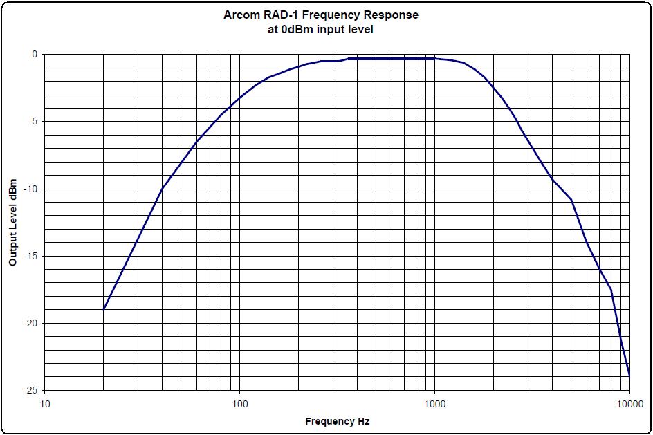
The unit had about 0.3dB loss at 1 kHz; that's negligible. The frequency response was primarily the normal voice range, and was 3dB down at 100 Hz and 2.2 kHz. The graph below shows the overall frequency response.
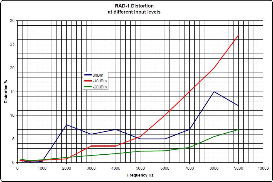
I checked the distortion at 100, 500, and every 1 kHz from 1 kHz to 9 kHz using three input levels: 0dBm (0.775Vrms), -10dBm (0.245Vrms), and -20dBm (0.0775Vrms). Below 100 Hz the distortion rises a bit to almost 1% regardless of the input level. The distortion was much higher above 2 kHz and the higher the input level, the higher the distortion. The graph below shows the distortion.
The COS input starts muting the audio coming out of the unit when the voltage goes above about 3VDC. The maximum attenuation of 70dB occurs at about 4.2VDC. The COS signal should be pulled up to +5V in order to fully mute the audio. Due to the way the audio is muted (bipolar transistors shunting the audio signal), distortion rises drastically when the COS input is between the above two points, but 70dB is definitely plenty of attenuation.
The delay adjustment pot on the board increases the delay as the pot is turned counter-clockwise. I did not measure the actual delay but it was definitely present.
The unit requires about 7VDC minimum to function properly. The audio output level did not vary as the supply voltage was increased. The audio delay IC operates on 5VDC and the regulator needs a couple of volts more to function properly. The unit draws about 20mA, slightly lower (18mA) with no audio signal present.
Conclusions:
First, I'd install the 5-pin male header then clean the flux off the board.
My intended use of the RAD1 was to eliminate the squelch noise burst on the de-emphasized and muted output of a low-band MaxTrac mobile radio that has a level of up to 0.8Vrms (just over 0dBm). I would need to reduce the audio signal by 10-20dB to reduce the distortion to an acceptable level. I could modify the RAD to reduce the input amplifier's gain by 20dB and increase the output amplifier's gain by 20dB. This would also vastly reduce the distortion by running the delay chip at a much lower audio level.
The audio response has about an 8dB/octave roll-off above 2 kHz, which would seriously affect the high frequency response of the MaxTrac's already de-emphasized audio output. I would need to use a flat non-muted audio output to counteract the high frequency roll-off present in this device. Fortunately the MaxTrac offers that as an option, and the audio level is much lower, but I'd have to amplify the audio to properly feed the next stage after the delay. I don't know what components are producing this roll-off so it might not be easy to fix this issue.
Test Equipment Used:
HP 339A Distortion Measurement Set
Heathkit IP-28 Variable DC Power Supply
Fluke 189 Digital Multimeter
Contact Information:
The author can be contacted at: his-callsign [ at ] comcast [ dot ] net.
Back to the top of the page
Up one level (Arcom index)
Back to Home
This page originally posted on Wednesday 11-Dec-2019
Article text, artistic layout, all images, and hand-coded HTML © Copyright 2019 by Robert W. Meister WA1MIK.
This web page, this web site, the information presented in and on its pages and in these modifications and conversions is © Copyrighted 1995 and (date of last update) by Kevin Custer W3KKC and multiple originating authors. All Rights Reserved, including that of paper and web publication elsewhere.