Comments / critiques / contributions / suggestions on this page are welcome.
First note that if you are going to work on a troublesome power supply that
you need a way to test it - to put a load on it... not something that can be
damaged if that supply suddenly puts out too much voltage. Consider using things
like auto headlight bulbs, stove burners, water heating elements, maybe preheat glow
plugs for diesel engines. I once saw a set of automotive jumper cables and a length
of galvanized water pipe used to put a 40 amp load on a 70 amp Astron... slide the
jumper cable clamp along the pipe to adjust the current, then clamp it there.
A friend took a electric clothes dryer heating element - which was a structured as
two elements in series and modified it into multiple elements. He then added several
knife switches, one to each element section. He ended up with a load that could be anything
from 2 to 50 amps at 12 volts. And the old dryer blower fan ran on 120 volts...
that gave him forced air cooling on the restructured heating element...
There are a lot of ways to dissipate 12 volts and high amps without risking
something valuable - like an expensive HF radio. You might want to
look here
then come back to this page.
Second, note that the Astron, Pyramid and similar linear power supplies
are all made to a price point, and to meet that point they are missing a
number of design elements that protect either the radio or the power supply.
For example: The outer case on the pass transistors on the heat sink(s)
are live with about 24-28 volts (on a 12 volt supply... about double that
on a 28 volt supply). The pass transistors are isolated from the grounded
chassis and heat sink(s) but the transistor cases are not covered so the potential is
there to cause problems if any external conducting item shorts the case of a
pass transistor to the heat sink or the case (i.e. ground)... that can
instantly destroy them. If this could be an issue for you then you might
want to order some of these transistor covers.
Ron Rogers WW8RR noted that...
If your Astron is going into current limit at random times a VERY
common cause of random current limit shutdown in linear Astron
supplies is due to the manufacturing process: a bad solder joint on the
collector tab of one of the pass transistors. During manufacture they
solder the buss wire from collector to collector. If you take a pair of
pliers and grab the buss wire next to the solder joint at each transistor
and pull on it, you will most likely find one that will simply pull off.
All it takes is for one of those transistors all wired in parallel to
have a bad collector‑to‑buss solder joint and all of the source
current from the supply tries to flow through the Emitter-Base junction of
that one transistor that has the bad solder joint. Bingo !!! Immediate
current limit mode!!
If your supply is going into occasional crowbar triggering it could be
sevral things... Ray Maynard NØLGR wrote an article about one situation
here. His modification
is a recommended one for any remotely located Astron, like at a repeater site.
In another Astron failure situation Jeff Banke NZ2S described the cure: it was a
faulty 0.01uf ceramic capacitor (labeled as C10 on some schematics, unlabeled on
others, and the capacitor completely missing on a few schematics) between the
case and collector of the TIP29 driver transistor. On an ohmmeter the faulty
capacitor measured about 6 to 7 thousand ohms instead of the infinite resistance
it should have. This resistance allowed current to flow in the driver transistor
which caused more current to flow in the pass transistors. This caused the
output voltage to rise which triggered the overvoltage protection crowbar circuit.
This puts a direct short across the output of the power supply, which is current
limited to about 80% of the rating: 28 amps on his 35 amp power supply.
Crowbars are designed to save any equipment attached to the PSU. This protection was
working, and saved an Icom IC-7300 HF radio and a IC-9700 VHF/UHF/1.2 GHz
from damage, however it was cooking everything inside the Astron, which would have
eventually caused a major failure of pass transistors, driver transistors and the
LM-723 regulator IC, or possibly a fire. Fortunately the owner was present and
noticed the way-too-hot power supply and switched it off. The pass transistors were too
hot to touch, and got hot enough to cook food on within 30 seconds after power on.
This could be prevented by adding a simple fuse holder (or a 12 volt DC circuit
breaker) after the bridge rectifier output and before the pass transistors...
But circuit breakers have their own characteristics...
From another email to repeater-builder: A word on circuit breakers, both
AC (120 volts or 240 volts) and DC (12 to 48 volts)...
There are lots of misconceptions about circuit breakers, how they work, what the protect and HOW THEY TRIP.
You probably assume that a breaker is a perfect device and will prevent you from getting into trouble as you keep pushing the limits. THEY LIKEY WON'T.
AC breakers are both thermal (heat sensitive to trip on sustained, minor overloads but take exponential amounts of time) and magnetic (trip rapidly on a big surge like a short circuit). Typically, small overloads can operate for double-digit minutes to hours before they cause a breaker to trip, allowing connected devices ample opportunity to melt (like an overloaded extension cord).
Most DC breakers are ONLY thermal trip and should not be substituted for AC breakers.
Fuses operate by heating until they melt. They heat in a non-linear fashion. On slight overloads they heat up and the fuse wire slowly sags. The solder at the ends may soften and crystalize and the fuse becomes intermittent. A short may vaporize the fuse wire, and if a glass fuse it will deposit on the inside of the glass and darken it. A high amperage fuse operated at or near it's limits may generate a lot of heat and that heat can get conducted down the highly conductive copper wire... it is not uncommon for the insulation on the wiring near a high-amperage fuse to fail, even at the point of charring.
This is a good reference: Circuit Breaker Myths.
A quality breaker should trip at around 130% of their rated capacity in single digit seconds.
From yet another email to repeater-builder:
Another common failure (these supplies are full of them) is due to the use of
parallel‑wired diode bridge rectifiers. A good example is on the RS‑35
supply schematics. They use two packaged bridge rectifiers that
are wired in parallel with pieces of #10 wire tying them together with no
attempt at current equalization. To use a Martha Stewart term, this is
A Bad Thing, engineering-wise; at least the designer used current
balancing / equalizing resistors on the pass transistors. If you
look at the schematic you will see that only the positive halves of the
bridge rectifier(s) are used; the negative ends are left floating. Unless
the two bridges are absolutely identical, or at lease very closely balanced,
one will hog most / all of the current and the other will just sit
there and watch. Eventually one diode will short or open, and that often takes
the other one along with it. This causes the supply's primary fuse to blow. If
your supply instantly blows the primary fuse (and it's not the MOV, referenced
later in this article), then you need to unsolder the two heavy transformer
wires (frequently colored yellow) from the bridge rectifier terminals and then
see if a new fuse blows. If not, check for a shorted main filter capacitor and
shorted pass transistors. If all checks out OK, chances are high that one or
more diodes have shorted. They have to be completely unwired to be properly
checked. In 2007 I bought several KEST KBPC 5010 or KEST KBPC‑5010
1,000V 50 amp diode bridges for about US$5 each as replacements and just use
one of those in place of the two parts in parallel in RS‑35s. In 2020
MPJA.COM had a 50 amp 1kv unit for $2.
Click here for the KBPC-5010 data sheet.
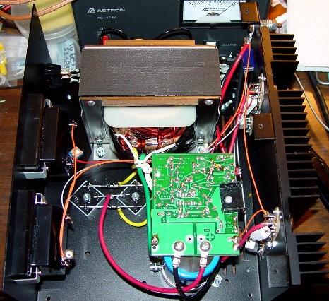
Here's a photo of the inside of a dual-rectifier Astron RS‑35.
|
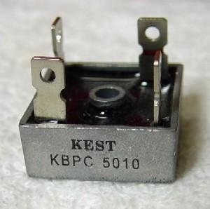
Here's a photo of the 50 amp replacement. It's the same physical size as
one of the existing rectifiers.
|
|
Both photos above are courtesy of Robert Meister WA1MIK and were taken
to illustrate the above situation.
|
Astron used different transistors at different times in their history. Don't be
surprised if the ones in your supply are not listed in the table below (and if they
are not, please let us know what you find). Just Google the part number and you will
find the info somewhere on the web.
From an email to repeater-builder from an amateur that works in the power supply
design field...
Next to the regulator chip, the pass transistors and thjeir heat sink are the heart
of the supply. Astron started out with 2N3055 devices, which are good for 10 amps
per paralleled device and used 2N3771s in the higher current units. When the price
on the 2N3771 devices dropped low enough they switched to that device completely.
They now use the 2N3771 exclusively, even on 28 volt power supplies.
In 2020 MPJA.COM had new 2N3771s for $1.95, occasionally on sale for 75 cents.
For those that want details, here you are:
Transistor
Part
Number |
IC
Collector
Amps
(see note) |
BVCEO
Breakdown
Voltage |
hFE
Gain
min‑max
at IC |
PD
Power
Dissipation
in watts |
DigiKey
Price
each
(Sep 2018) |
Comments |
| 2N3055 |
10 |
60 |
20-70 @ 4a |
75 |
$3.51 |
Used in the earliest lower amperage Astrons |
2N3771
ECG-181 |
30 |
40 |
15-60 @ 15a |
150 |
$3.91 |
Used by Astron |
| 2N3772 |
20 |
60 |
15 @ 10a |
150 |
$4.33 |
|
| 2N3773 |
16 |
140 |
50-60 @ 8a |
150 |
$3.91 |
May be been used by Astron |
| 2N5301 |
30 |
40 |
15-60 @ 15a |
200 |
$7.06 |
|
| 2N5302 |
30 |
60 |
15-60 @ 15a |
200 |
$4.60 |
|
| 2N5686 |
50 |
80 |
15-60 @ 25a |
300 |
$13.81 |
Recommended high current replacement.
Note: The base and emitter pins are a larger diameter and may require eliminating any transistor sockets. |
| MJ15003 |
20 |
140 |
25-150 @ 5a |
250 |
$4.41 |
|
| MJ21196 |
16 |
250 |
25-100 @ 8a |
250 |
$4.21 |
|
Note that The maximum collector current specified above is only
valid as long as the internal transistor chip temperature is less
than the rated maximum temperature for the device (and you want
keep the temperature under control... a fan on the repeater power
supply heat sink is a good idea).
Also note that the higher-numbered 2N3773 has a maximum current
of about 1/2 that of the lower-numbered 2N3771.
All the devices listed in the table above are drop‑in
replacements with better performance for a very reasonable price
EXCEPT for the larger diameter of the base and emitter pins on
the 2N5686s. The larger diameter precludes the use of the stock
(factory) sockets.
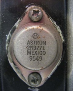
One of the two pass transistors on the heat sink of an RS‑20.
The "9549" is a date code and indicates that the
transistor was made in the 49th week of 1995.
Back to the email:
The "book" rated dissipation of a power transistor is noted in
the book as having been measured at at 25°C (77° F). As
the temperature goes up, the power dissipation ability goes
down. During long heavy load situations (like a long repeater
transmitter key-down session) the internal chip temperature of the
pass transistors will be a lot hotter than the case, which will be
hotter than the heat sink. The characteristic that causes a
time lag between internal chip temperature rising and the heat sink
temperature rising is called thermal resistance. Think of the
situation as including a "heat pipe" between the source
(the transistors) and the destination (the heat sink) - like
water, the larger the diameter of the pipe, the greater
the quantity flowing, and the lower the thermal resistance,
the faster the transistor can dump the heat into the heat
sink. You can't do anything about the thermal resistance
between the internal chip and the case of the power transistor
(i.e. the internal construction of the power transistor), but
you can lower the thermal resistance between the transistor
case and the heat sink with an application of the proper type
and amount of heat sink compound. And you can add a fan blowing
air across the heat sink to help it shed the heat. Note that due
to the density of the air a fan on a heat sink at a mountaintop
site at 5,000 feet won't cool as well as the same fan on the same
heat sink at sea level, fortunately mountaintop sites are
generally cooler than at sea level.
More notes on fans below, including a link to very interesting
article on the effectiveness of a fan by John Huggins KX4O.
The 2N3055s, 2N3771s and 2N3772s have been found in known-stock
Astrons (as was said above the 2N3055 is found only in the earliest
and smallest units and Astron switched completely to the 2N3771 at
some point). The 2N3773s, 2N5301s, 2N5302s and ECG181s have
been found in used ones bought at swap meets or handed to me for
repair. The 2N3773s may have been stock (if they were replacements
they were very nicely done, and I couldn't tell), the 2N5301s and
2N5302s were obvious field replacements.
My personal rule on rectifier diodes and pass transistors is
at-least-double-the-rated-current of the supply. I use the
2N5686 exclusively as a replacement in the larger supplies
as not one supply I have rebuilt with them (over 20) has EVER come
back to haunt me (at least for a pass transistor problem). Yes,
in most cases they are total overkill and they do cost more, but the price
difference on four new devices for an RS‑35 is around $25, even if
the originals are 2N3055s or 2N3773s. If you find 2N3055s in your used
supply and don't want to go to 2N5686s at least replace them with 2N3773s,
and preferrably 2N3771s. The 3773s provides 60% more current capacity
than a 2N3055 and twice the power dissipation for an additional 25 cents
each. If you use 2N3771s (which is what Astron themselves uses)
that's triple the current for an additional 50 cents each.
And think about it: If you go cheap what is a future power supply
failure, the down time, a round trip to the repeater site (don't forget
to consider the price of vehicle wear and tear plus the gasoline)
and ANOTHER power supply (or repeater) rebuild going to cost? What
is your time worth? How much gas will you burn for a trip to the
repeater site? One of my sites is three hours one way...
Don't mix the pass transistor types !!! The emitter
ballast resistors do their balancing act only when the transistors
are identical. Always replace a dead pass transistor with
an identical part number, or if you can't find an exact match,
then replace all of them as a group. And don't go down in
ratings - if you find 2N3771s do not replace them with 2N3773s
or 2N3055s. My own short rule of thumb: Use only the
2N3771s or 2N5686s - and use all of one or the other.
If you have to replace all of the pass transistors in a supply,
and if the old ones are 2N3055s or 2N3773s do yourself a favor
and buy something larger ‑ at least 2N3771s (also known
as the ECG181) and preferably 2N5686s. Note that sometimes you
can use fewer of the 2N5686 than the 2N3771s that came with the
supply.
A note from Mike WA6ILQ:
Note that on some models it may not be worth the upgrade parts
or the effort to install them . The RS‑7 uses a
single 2N3771, a 30 amp device. The RS‑12 uses
(used?) a pair of 2N3771s (the dual transisitors are obviously
a holdover from the days of 2N3055 pass transistors as each one
was only good for 10 amps)... so the stock RS‑12
has 60 amps worth of pass transistors for a supply they
rated at 12 amps (but is only good for 5-6 amps continuous)... On
the RS‑7 and RS‑12 (and similar low current supplies),
at least, save your modification time and money.
Jeff Banke NZ2S wrote in an email in 2020...
On the topic of transistors in Astron/Pyramid supplies and similar devices, as I pointed out previously since the pass transistors are a point of failure, in these supplies it probably is due to the underrated heatsink and the underrated pass transistors. Given the possibility of a catastrophic failure where the 30v is shunted to ground by virtue of the crowbar and the driving transistor is NOT getting turned off by the current limiting chain as can happen with the capacitor between the base and collector going leaky. This means in the case of the RS35, 35Ax30v=1050w passing through the pass transistors, which are 150W devices, (150x4=600w), which is far in excess of their capability, and as such will fail in short order. Even at the continuous rating of 2Ax30v=810w which is still in excess of the capability of the pass tr's. Hence the move to the 2N5686, a 300w device, and the move to the TIP120/121 as a drive device (5A capability at high HFE). This combination is working in several PSU's at the moment, but if one wanted to beef it up further, it is possible to go to a TIP142, another Darlington device which has a 10 capability at an HFE of 500. I will be trying this combination in my next PSU rebuild.
One tool that is worth purchasing: a non-contact IR thermometer.
Use it to measure your heat sink under full load. If your heatsink
is 180c (350f), then your transistor junction temperatures are
probably over 200c (395f) and your devices are at the edge of
destruction. And you are probably heat stressing the solder
joints. You need to get your heatsink down to 125-130c (255-266f)
or so. Even a slow fan will make a very big difference over still
air and convection cooling.
Back to the email:
If you find one bad pass transistor make sure you measure
the resistance of all of the emitter ballast resistors
(the current balancing resistors) and compare each
against the others. If even one is different,
replace ALL of them with new 5% (or better) units - that
way you have identical values (after all, they are
supposed to evenly distribute or balance the current,
and can't if they are not absolutely identical in
resistance). Using all new from the same batch
is the simplest practical way to get identical values.
The first thing I do when debugging older linear power supplies
is to remove the pass transistors, because the heat sink compound
frequently dries out, turns to powder, and needs replacing. Of
course while they are out check them to make sure they are OK.
And I add the lock washers when I reinstall them (see below).
Don't forget to use some good thermal compound. I prefer
Wakefield 120,
available from
Digi-Key,
Mouser
or Amazon, and a reasonable
substitute is
Dow Corning #340. Both are good, but don't go
overboard - you want just enough to put a
thin layer between the transistor and the insulator,
and again between the insulator and the heat sink. All you
are doing is eliminating any air pockets.
If you can't find the Wakefield #120 or Dow Corning #340 stuff then
use the "Arctic Silver" that is made for use between
the CPU chips and the heat sinks in high-end PCs.
As long as I am inside the Astron I also do the following:
- Some Astron models use stud mount rectifier diodes, others use
one or two rectifier blocks in parallel. The ones that use dual rectifier
blocks get them replaced with a single rectifier block rated at least
2 times the maximum current of the supply, if not 3 or 4 times. Yes,
I'll use a 50 amp bridge in a 12 amp supply. It's cheap and I won't
have to worry about it ever again. Some of the larger supplies
that use a pair of rectifier blocks get converted to 75 amp or
100 amp stud‑mount diodes. Astron uses two 40 amp diodes in
parallel on each side of the transformer in an RS‑70,
personally I feel that's not enough headroom (my rule on rectifiers
is at-least-double-the-rated-current), and besides, they aren't using
any current balancing components on the diode pairs. In the last
RS-70 I rebuilt I used two 200 amp diodes (only because the surplus
store was out of the 150 amp ones), and because I used one on
each side of the transformer there was no balancing required.
- I add a 0.1 µf capacitor rated at 100 volts (or better)
from the positive terminal of the large bridge rectifier to ground.
- I add three 0.01µf 600 volt (or better) bypass caps - one
across the AC line and one more from each side of the AC line to
ground, and I use the gap-cap version of the bypass cap if I can
have them in stock (see
http://www.vishay.com/docs/28521/gapkap.pdf).
If you are going to google it then note that Vishay calls it a
"gap-kap". Search for the Vishay 0.01µf
S103M69Z5U283L0R. I've found a single cheap ceramic bypass cap across
the mains power line in some of the Astrons I've worked on, most don't
have it. And since the Astron is on my bench because it has problems,
I assume the existing bypass cap (if any) is damaged and it gets replaced.
- I add three 150 volt Metal-Oxide Varistors (MOVs) - one
in parallel with each of the gap-caps mentioned above (areas with
220 / 240 volt AC mains will need higher voltage
devices). Some Astrons already have one MOV (across the
power line) already in place. Due to the normal failure mode
of a varistor (see the "Regarding MOVs" paragraph below), and
due to the reason that the Astron is on my bench is because it
has problems, I assume the existing varistor(s) (if there are
any) is (are) toasted and trash it (them). See the MOV note
below for the preferred part number.
- I add the missing compensation capacitor (470pf or
500pf) - see the 723 data sheet and the text above.
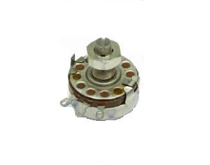
- I relocate the voltage set pot. Astron uses a very
cheap open frame single turn potentiomenter on the underside
(component side) of the regulator board. This pot can get
dirty and become intermittent. I remove their pot and replace
it with a sealed pot that is soldered to the top side
(foil side) of the board, positioned for easy access and
adjustment. And I use a 10-turn pot if I have one in stock.
- I test the connection from the chassis to the ground prong
of the power plug. Use your ohm meter on the x1 scale to
test between the case to the ground of the AC mains power plug (the
round prong in the USA). It should show zero ohms. I've
worked on several Astrons that arrived with a non-functional safety
ground wire in the power cord. I scrape away the paint and
add a star washer under the power cord green wire lug. On
one I found the ground lug crimped onto an insulated wire (i.e. they
hadn't stripped the wire before they crimped the lug onto it). In
each case the housing / chassis was floating above mains power
safety ground. Remember the power plug ground wire is a SAFETY
ground, and your survivors will appreciate it if you don't scrimp
on the safety. Make it a good solid ground. And remember that the
"green" wire in the power cord may be green with a yellow
stripe or stripes.
Update: Some Astrons use a multipoint terminal strip with the green
wire soldered to the grounded lug. See the photos in the article on
the index page that is titled
"Reducing Inrush
(Surge) Current on Astron Power Supplies". The final
test is the same, make sure the resistance between the case and to
the round (ground) pin of the AC mains power plug is zero ohms.
- Some Astrons have the negative side of the DC output grounded to
the power supply case, some float it, some have a resistor. You want the
negative side floating. Again, use your ohm meter to test between the
negative terminal on the case to the ground (round prong) of the AC power
plug.
Note from Mike WA6ILQ: See the article
here on the topic.
- I add split or star lock washers under the pass transistor mounting
screws. I've seen thermal cycling loosen them.
Note from Mike WA6ILQ: The voltage regulator board is mounted to the
filter capacitor in the higher amperage supplies by the screws that are the
terminals of one of the filter capacitors (see the RS-35 internals photo
above). In one case I found that one of the filter capacitor screw holes
had not been adequately drilled before the hole was tapped and while the
screw was tight (it was bottomed out in the capacitor hole) it was NOT
making a solid contact with the regulator board. I could have fixed it
with a shorter screw, I chose to simply add a lock washer as a shim.
Naturally, I used two, one under each capacitor screw head. And that's
not the first time that a a finger-tight capacitor screw has been found,
there's an email below that describes a random crowbar situation caused
by the same situation.
- Most of the time I relocate the voltage adjustment pot to the front
panel, mounted under the voltmeter (if it is a metered supply). The
voltage adjustment is a carbon linear pot. I simply mount a
screwdriver-adjust pot (of the proper resistance and of
the type that has a locking nut
on the adjustment), and run wires to the pads where the regulator board
voltage pot used to be. I use a three conductor
shielded wire for this (that's three wires plus the shield), and ground the
board end of the shield. By the way, the vertical tab on the left side of
the pot in the photo is an anti-rotation feature - it prevents the pot from
rotating in the front panel. When you mount that style of pot you need to
drill two holes - a large one for the center shaft and a second one just
large enough to clear the anti-rotation tab. And sometimes the
anti-rotation tab is taller than the front panel is thick, you may
have to shorten it a little (a pair of diagonal cutters and a flat file
to take the burrs off works just fine for this).
Note from Mike WA6ILQ:
This article shows a better way:
Adding Voltage and Current Adjust Pots to an Astron 13.8V Linear Supply
by WA1MIK
- On the VS series, and on the supplies where I relocate the voltage
adjust pot to the front panel I add three ferrite beads, one on each lead
of the front panel potentiometer(s) right at the PC board (but not on the
shield). If necessary a drop of hot melt glue holds the bead in
place. Some of my Astrons are at broadcast sites, and I don't need high
RF levels confusing the voltage regulators, the overcurrent foldback
circuit, or the crowbar circuit.
Note from Mike WA6ILQ: The internal voltage adjust pot in the Astron can
adjust the voltage up to the point where the crowbar trips. A
better way of wiring a front panel pot into the Astron regulator board
is described in the Robert W. Meister WA1MIK article titled "Adding Voltage and Current
Adjust Pots to an Astron 13.8V Linear Supply".
Astron supplies have a non-adjustable current limit feature that can be
made adjustable. The WA1MIK article describes how to do that as
well. I highly recommend adding both to your workbench and radio
site Astrons. Use the above mentioned shielded wire and ferrite beads
is recommended and can't hurt.
Note that Astron BB series supplies are adjusted differently, as the
load they see is a combination of the repeater and the battery... and
if the mains power has just been restored after a long outage an Astron
with a stock Current Limit circuit that is charging a large battery is
going to let the battery suck some serious charging current and the
Astron will current limit which may affect the performance of the
load (your repeater). If you have a large battery bank then you will
want to limit the battery charging current (with a series resistance
of some value) to something that the supply can deliver to the load
and to the battery in continuous duty mode for many, many hours. In
that situation a fan on the heat sink is mandatory.
And one quirk with an Astron connected to a battery without a series
Shottky diode (to prevent backfeeding the supply): always turn the
PS "on" before attaching it to the battery.
- Check the wiring of the incoming power cord, the fuse holder, and
the power switch. Make sure the hot side is switched and fused.
A lot of Astrons have the power cord hot lead feed the fuse holder,
then the front panel power switch then the load (the transformer
primary). Some have the hot lead feed the switch, then the fuse holder
then the load. The second wiring method is preferred.
Make sure the fuse holder is wired properly - the rear end pin is
supposed to be fed by the power cord hot lead and the front ring
or sleeve of the fuse holder (nearest the panel) goes to the load (the
transformer primary). This is another life safety issue where your
survivors will thank you. The idea is that when you remove the fuse
from the holder the voltage source (the center pin) connection
is broken first.
In other words, the sequence of flow for the power should be from
the hot wire in the power cord (colored black in the USA) or
the "line" pin of the IEC power connector and go to one side of the
power switch, then from the other side of the switch to the tip (the rear)
of the fuse holder, and from the ring or barrel or front of the fuse holder
to the power transformer primary. The other side of the power transformer
should go to the neutral pin of the IEC connector or to the neutral wire
(white in the USA) in the power cord.
- I add an IEC style power cord fitting (available for free from a dead
PC power supply). Yes, it requires a bit of sheet metal work, but it's
worth it to prevent tripping over a dangling power cord again. I still
have scars from the rough concrete on the steps of one repeater building.
The IEC connector may not be appropriate for the high current units (i.e.
an RS‑50 or RS‑75) unless you can find a high current IEC and
a really heavy duty wire IEC power cord... something like #12 or #10 sized
copper inside the jacket... the last thing you want is for someone to slip
up and use a leftover wimpy #20 or #18 cord originally made for someone's
PC monitor. And label the power supply end of the #12 or #10 cord as where
it goes - you don't want some newbie who is helping out on his
first repeater site visit and has his head in the back of the rack
accidentally swapping the #10 sized cord for the main repeater RS-70 with
the #18 cord that feeds the link radio RS-12.
If you do chose to add an IEC power connector you need to make sure that
the current rating of the IEC connector is at least twice the measured
AC current draw of the supply at max DC load. Then you get to make sure
that it is wired properly - see this
drawing. Some IEC connectors have dots on the pins: brown is the
international standard for hot, blue for neutral, and green or yellow for
ground. Some manufacturers use molded-in lettering, "L"
for line, "N" for neutral, "G" or "E"
for ground or earth. Some even use both the molded letters
and the color dots. Whatever the markings are, you need to make sure
that the hot side is switched and fused and make sure the rear of the
fuseholder is wired to the IEC hot pin and the front of the fuseholder
is wired to the load (power supply power transformer) side.
Update from Mike WA6ILQ: Astron is now shipping some models with an IEC
power connector already installed. At least one has been found wired backwards
(line and neutral swapped).
- Most of the Astrons use a rocker-style power switch with an internal
neon lamp to indicate when the power is on. After a while the neon lamp
starts to flicker and finally dies from old age. I add a diffused (for
wide viewing angle) bright green LED to the front panel, with an
appropriate series resistor, and wired across the +12 volt DC output.
A bonus is that you can see when the internal filter capacitor is discharged.
Regarding MOVs, remember that they have a finite life and do wear
out. This is because when the voltage across a MOV reaches the breakover
point, the MOV avalanches and conducts therby shorting the excess impulse
energy into heat within the body of the MOV itself. If it draws enough
current the MOV just blows the input fuse in the device. If a MOV absorbs
a spike too big to digest they just short out. In that situation the shorted
MOV just blows the new fuse as soon as you replace it.
As I said above, if the voltage spike is not very energetic the MOV just
dissipates it as heat. The problem is, if the MOV gets hot enough,
the internal heat affects the MOVs internal characteristics - and the effect
is cumulative... the avalanche (breakover) voltage (the threshold voltage)
increases with each hit it takes. The next impulse comes along and less of it
gets shunted. If a MOV sees enough action, the threshold voltage goes up to
where it is effectively an open circuit. This slow change of the MOV threshold
voltage may take years. As you would expect, when the MOV is effectively open
the equipment protection is compromised to zero and you won't know it, but
physically the MOV still looks perfectly good.
This failure mode is why the common PC "surge protection" power
strips are a joke and a delusion - usually all that is inside is a single
unlabeled, bottom-of-the-quality-barrel MOV (it may not even be the
right voltage MOV, in multiple cases I've found unlabeled or a 260 or
280 volt MOV (i.e. one made for a 240 volt mains voltage) in a low-end
chinese made "surge protected" power strip sold for 120vAC
service in the USA. The Tripp-Lite "Isobar" units are much,
much better - and I use one as the rack cabinet power entry protection
at every repeater site (and they come with a warranty sheet that covers
the equipment plugged into the Isobar). MOVs are cheap, however, and if
they are the correct voltage are better than no protection at all. Just
make them your secondary layer of protection, and plan on replacing all
three of the MOVs every so often, especially if the power line feeding
the power supply has taken a lightning strike or apower surge (at which
point you replace all three, plus the gap-caps and then go looking for
further damage).
Another common MOV failure mode is where the MOV just plain shorts out
and vaporizes the fuse and frequently itself. I've seen MOVs reduced
to two bare leads waving in the breeze and bits of black or red plastic
scattered around the inside of the power supply case. But the supply was
repairable, and went back into service, and 8 years later (as I write
this paragraph in mid-2009) is still in service.
When you purchase new MOVs you need to make sure that you pick the
parameters properly. A MOV rated at 130 VAC is suitable for a
120 VAC circuit only if its tolerance is tight, say plus or minus 2%.
If your line voltage is a little high then it may be a good idea to install
new MOVs rated at 140 VAC with a 10% tolerance. Mouser (and others)
stock them. I use the Littlefuse V130LA20A, which is available
from Mouser for under 50 cents each (late 2009 price). In the
power supplies that have them Astron uses a V150LA10AP, which costs
$0.34 (summer of 2012). A 650kB
PDF data sheet for these parts can be downloaded here.
Don't bother with Radio Shack (their part 276-568, the last time I checked
they were over for $2 each (in 2009).
You would think that installation of the MOVs and gap-caps could be as simple
as soldering them right to the pins on the back of the IEC socket that you
installed in the back of the case, and yes, you can do that, it's just that
the plastic structure of many cheap IEC connectors melt from soldering iron
heat. Rather than unsolder and solder replacements on a supply that is
headed for an unmanned hilltop, it might be a better idea to connect the MOVs
and gap-kaps via a multi position screw terminal block bolted to the inside of
the cabinet just above the IEC socket. This allows you to replace them
without warming up a soldering iron. By the way, the dead-short failure
mode of the MOVs generates a LOT of heat, so mount that terminal block where a
long burst of heat that is much hotter than a soldering iron isn't going to
destroy an expensive part - like the 100,000µF filter cap in an RS-50.
As an aside, this failure mode inside a plastic cased low end "surge arrest"
or "surge protect" power strip is an invitation to a major fire - especially
if that power strip is sitting on a flammable surface, like on a carpeted or wooden
floor in a residence. Don't forget that most plastics are petroleum based
and are a very flammable fuel when melted (like from heat). This is yet one
more reason why I like the metal cased Tripp-Lite "Isobar" power
strips.
Note from Mike WA6ILQ:
One of the RS-20 Astrons that I own was purchased at a ham swap meet simply
becasue it was tagged with a simple note in big block letters on a 3x5 inch
file card taped to the top of the case... "NFG, blows fuses". I paid
$15 for it, took it home, popped the cover off, poked around with a VOM for
5 minutes, cut out the the old MOV with some side cutters and put in a
new fuse. The supply worked just fine. I did most of the critical mods listed on this
page (add 1 new compensation cap, one new .01µf cap from the positive side
of the rectifier to the negative side, three new V130LA20A MOVs, three new Vishay gap
caps, floated the negative output of the supply, verified the chassis ground (the
green / 3rd wire in the power cord), added split washers under the pass
transistor mounting screws and under the filter capacitor screw heads, added a
wide diffused and obnoxiously bright green LED to the 12 volt output, etc.)
and the unit is now the primary supply for a set of base station radios at a Red
Cross chapter building. The supply runs a set of a UHF Maxtrac, a VHF
Maxtrac, and a low band Maxtrac for the 47.42 MHz nationwide channel.
If the Astron I'm rebuilding is going to be powering a continuous duty
load (i.e. at a repeater site) I add a voltmeter, an ammeter, and if
it's a high duty cycle load (i.e. a busy repeater) a 24 volt DC fan (or
two 12 volt DC fans in series) blowing air across the heat sink... If
it's a busy repeater with large supply (with a wide heat sink) I'll use
definitely use two. A 24 volt DC fan operated on 12 volts
DC moves enough air to keep the supply heat sink cool and will last a lot
longer than a 12 voltfan running at normal speed. To save the fans
from running 24x7 you could use a simple SPST snap-action thermostatic
switch mounted on the heat sink. Just drill two small holes in a flat area
(even on one of the heatsink fins), and mount the switch with a dab of
thermal grease to ensure a good heat transfer. Another option to switch
the power to the fan(s) is a PTT-triggered timer so that the fans run only
when the repeater is actually in use. Many repeater controllers have digital
outputs that can be used to control other things, including a fan or a set
of fans. If your controller does, and the programming supports it,
you could have it ignore a kerchunk (i.e. a transmission of less than
30 seconds), yet turn othe fan(s) on when the repeater becomes
active (perhaps more than 60 seconds). If your repeater controller
has analog inputs and allows you to measure temperatures and allows you to
take action based on them then you can measure the power supply heat sink,
the transmitter heat sink (or both), then control the fans based on
that.
Don't forget that the power transformer and rectifier block need cooling
as well. Depending on the duty cycle you may want to add an
additional fan blowing air through the Astron housing. Note that the
bridge rectifier is going to drop about 0.7 volt to 0.8 volt at
anything up to the full load current. Let's say that you have an RS‑50
loaded to 50% current. 25 amps times 0.7 volts is 17.5 watts,
and that's only at half of the maximum current. 17 watts is a LOT of
heat for a small-package bridge rectifier to dissipate, especially with nothing
but convection cooling inside a sealed metal box. As easy as it
is to do, add a little dab of thermal grease under the rectifier block
and let the bottom plate of the supply shed some of the heat, or
remove the epoxy case unit and install a couple of heavy duty stud-mount
diodes into the inside of the rear heat sink.
Since the power transformer itself is not 100% efficient it will generate
some heat as well. If the outer case of the supply is so hot that you
can't put place the palm of your hand on it full time then it's worth punching
a 3 inch or 4 inch diameter hole in the top and bottom of the power
supply case, put copper screening over the holes and use a 24v fan to force some
air flow over the internal components (punching one of the holes in one side
of the lid and the other in the other side of the bottom results in cross-wise
air flow at zero cost). If cabinet clearances are tight (i.e. no room
above or below, like in most rack mounted repeater systems), I'll punch both
ends of the Astron cabinet, add two pieces of copper screening and mount the
internal fan on the outside over the intake hole (in general, pushing air into
a cabinet cools better than sucking air out). Don't forget a finger
guard of some form.
(end of the email)
Note from Eric Lemmon WB6FLY:
One good choice of snap action switch is the Cantherm Corp. R2005015
normally-open thermostat that closes at 50 degrees C (about
122 degrees F). When attached to a heat-sink fin, it
turns the fan on when necessary, and keeps it on until the heat sink
cools below about 100 degrees F (right around body temperature). This
particular switch is available from Digi-Key as Catalog Number 317-1094-ND,
for about $9 each (2005 price).
More on fans below, including a link to very interesting article on the
effectiveness of a fan by John Huggins KX4O.
Some notes and comments on the above email from Mike WA6ILQ:
a) If you end up modifying the wiring in the AC side (to change the
switch-fuse sequence, or to add gap-kaps, MOVs or an IEC connector) it
wouldn't hurt to add a couple of snap-on ferrite chokes... just snap one
on the hot wire and a second on the neutral wire, both just inside the
back wall of the cabinet.
b) Copper screening (also known as copper mesh) is stocked by many model
airplane / hobby stores and you will find that it is easy to solder
a grounding pigtail to it. Copper screening is very soft, be gentle with it. If
you can't find it locally then check the
Georgia Copper web site. They sell
"copper mesh"
in 12 inch by 12 inch (30cm by 30cm) squares - but the minimum shipping cost
is enough that you will want to pool an order from several people and / or
several projects.
Another source is Amazon - they sometimes have it in stock here. However it's a tighter weave and somewhat restricts the airflow.
c) Remember that fans don't cool anything, they just move air. Any
particular fan only cools if the air that it moves is sourced from a lower
temperature. Make sure that your "cooling fan" has a
source of cooler air.
d) A constantly operating fan can pull a lot of dust and dirt into the
equipment, especially if it's pulling from floor level. Besides, the
fan is ineffective until the device(s) get(s) warmer than the air around it,
so starting the fan immediately upon key-up can be a waste. In my opinion,
a snap-action thermal switch mounted on the heat sink (even if it's just on
a fin) is the simplest and most practical means of controlling a fan, and a
repeater controller timer is the second simplest. If you are going to
mount a fan to push some air through the Astron cabinet then you are probably
also adding a fan to blow air across the heat sink. Just wire the fan
motors in parallel.
e) If you are going to add a fan (or two) to a repeater site power supply (actually,
any device) make sure you use a new name-brand ball bearing fan - cheap
fans use brass or bronze bushings, cheaper fans use plastic bushings, good fans
use metal ball bearings and are worth the extra money. Fans with cylindrical
or tapered needle bearings are even better (i.e. mil-spec quality) but not too
common and when they are found are usually expensive.
f) This goes hand-in-hand with the previous comment. Don't buy surplus fans
for a rarely-visited repeater site. Bite the bullet and buy new quality ball bearing
fans. I don't need to make yet another hill trip to replace a failed used fan.
Some of my hilltops are two hours on the highway plus another hour or two on a
4x4 road, and that's one way. And you never go to a hilltop alone, so any trip
ties up two people for most of a day. And I've had to make a 7 hour round
trip just to change a fuse.
Think about what piece of hardware a fan failure is going to affect - how
much equipment will you have to replace? RF power amplifiers are not cheap. Power
supplies are not cheap, and when they fail they might take something else with them.
Save the questionable used fans for something that is easy to get to and fix. I've
seen surplus fans advertised as "new old stock" where I suspect the seller
took a used fan, cleaned it up, popped the bearing cap, added fresh grease, and then
replaced the cap. No, thank you. As was said in the above email, "If you go
cheap what is a future power supply failure, the down time, a round trip to the
repeater site (don't forget to consider the price of vehicle wear and tear plus the
gasoline) and ANOTHER power supply rebuild going to cost? What is your time
worth?"
g) John Huggins KX4O did some research and measured the effectiveness
of a fan at various distances from a heat source, then wrote
an interesting article.
h) In the time from when this article was initially written and the time
of an update Robert Meister WA1MIK wrote two highly relevant
modification articles that I recommend that you consider for your radio
site and workbench Astrons:
1) Reducing Inrush (Surge) Current on Astron Power Supplies
2) Adding Voltage and Current Adjust Pots to an Astron 13.8V Linear Supply
Several items in the email above can be done at almost zero parts cost. Adding a
dab of heat sink compound under the rectifier block(s) is almost free as well. Adding
the compensation cap in item 5 is mandatory for repeater or other high level RF sites
or customer sites, and optional for the workbench.
Troubleshooting and Repairs:
When you are repairing or modifying a power supply - of any
brand - you really don't want to use a real radio, etc. as a test
load. There are several failure modes that would put the
full unregulated voltage (as much as 29 volts DC in a 12 volt Astron)
across the load. It's much better to have a
made-for-the-job test load, and folks have used things
like old car headlights that have one filament burned out,
etc. I once saw a test load made up of four old headlights,
with four pull-push headlight switches and a single
ammeter. The owner had bought the bulbs and switches from a
junkyard. The particular bulbs he had purchased had two
good filaments, and each switch controlled one headlamp - when
pulled half way out the low beam came on and when pulled all of
the way out added the high beam.
Tony King W4ZT had a need for a test load and created
a web page about it.
I was sent a PDF of it, which can be found
here.
Later I found the original web page mentioned above.
Transformer Failures:
From another email to repeater-builder describing another failure
mode, and the fix:
Most of the Astron designs have a single secondary winding with three
taps for a total of 5 wires, with the center section being the heavy
(high current) wire and the two outer sections use much thinner wire
(it is just for powering the voltage regulator board). See the
diagram below:
-----------------    -----------------   Thin wire (to the voltage regulator board)
                 )  (
                 )  (
                 )  (  Thin wire section of the secondary winding
                 )  (
Primary winding  )  (
                 )   -----------------   Thick wire (high current) to main rectifiers
                 )  (
                 )  (
                 )  (  Thick wire section of the secondary winding
                 )  (
                 )  (
On the 120/240   )   -----------------   Center tap (thick wire)
models the       )  (
primary is in    )  (
two sections     )  (  Thick wire section of the secondary winding
that are in      )  (
parallel for     )  (
120vAC and in    )   -----------------   Thick wire (high current) to main rectifiers
series for       )  (
240vAC           )  (
                 )  (  Thin wire section of the secondary winding
                 )  (
                 )  (
-----------------    -----------------   Thin wire (to the voltage regulator board)
|
I've seen two supplies with one of the outer sections opened
up. There is no way to do a stock repair of it short of a new transformer
(or having the old transformer rewound). The inexpensive method to salvage
the supply is to abandon the thin-wire section and move the two thin wires
from the regulator board to the secondary of an added small separate 24 volt AC
transformer. There is plenty of room inside the cabinet for it. Do
the next guy a favor and leave a note inside the cabinet as to why the
extra transformer is there.
Drifting Output Voltage:
From another email:
...a recent problem I had with an Astron RS-20A:
The symptom: low output (7-10 volts) and randomly varying
I replaced the 723 regulator chip and the TIP29 base drive transistor with no effect.
I replaced all of the diodes on the regulator board with no effect.
I checked the pass transistors. Both were good.
I finally changed the .01µF cap that is connected to pin 13 of the 723 chip
and that fixed it.
Evidently the cap was breaking down or leaking internally and causing the 723 to
vary the output voltage.
Random Crowbar Tripping:
From another email:
...although the auto reset circuit seemed to help, we finally found
the real issue in the RM-35M supply at the repeater site. As this may
affect other units in the field I wanted to pass along what we found:
On this particular power supply the screw they used to fasten the regulator
board to the top of the filter capacitor was too long and bottomed out before
snugging up the connection. That in turn caused a bad high resistance
connection that overheated and caused the intermittent triggering of the
over voltage circuit. Although I had pounded on the unit, it never
showed up on the bench. It finally got hot enough to burn the board
and damage the capacitor. I would highly suggest that readers check
their supply and if they find a similar situation that they add an inside
or outside star style lock washer between the board on the first ring
terminal and another between the two ring terminals. That should
take enough slop out of it not to bottom the screws and cause a flaky
connection.
After your page author saw that he started looking at Astrons and found
the same issue. He now adds star washers on the capacitor screws.
AC Mains Fusing:
Most of the Astron schematics show a fuse in the AC mains side of the
transformer. Some of them do not specify slow-blow or fast blow. You
will want to use a slow-blow fuse rated at the mains voltage (or greater)
when powering a highly inductive load, like a big transformer or
motor. There are "32 volt" fuses made for low voltage
circuits (i.e. 12v automotive, 24v industrial electronics, etc). Don't
use them - you want one rated at 125 volts (mains voltage in the USA) or
250 volts (in localities where 220 or 240 volt circuits are used). Linear
supplies draw a lot of current during the first few cycles of the AC voltage
after being switched on as the capacitors charge. If there really is
a short circuit the excessive current draw will blow the slow-blow fuse
rather quickly.
Bob Meister WA1MIK wrote an article on that
topic - "Reducing Inrush (Surge) Current
on Astron Power Supplies". In that article he describes how he added a
thermistor in series with the transformer which reduced the surge current
and eliminating annoying circuit breaker trips and the typical "thump" on turn-on.
The fuse that came in my stock RS‑35M supply (probably 20+ years ago)
is a Littelfuse part number 326008. That is an 8 amp, 250 volt,
Slo-Blo fuse with a ceramic body, also known as type 3AB (the common fast-blow
3AG is a glass barreled fuse). The labeling on the back of the supply just
says "8A" without saying fast or slow blow. Some lower rated
supplies use a 5 amp or even smaller fuse. If someone else is going to
be servicing your repeater(s) it wouldn't hurt to add a label reading
"Use 8 amp slow blow ceramic fuses ONLY" (replace the
"8A" with the appropriage amperage for your supply), and
put a few fuses into the on‑site toolbox. Or put some fuses
in a zip-lock bag along with a magnet and use the magnet to stick
the bag to the front, top or side of the steel power suply housing. On
a bench supply you could even jumper out the fuse and replace the on-off
switch on the front panel with a toggle-switch style slow‑blow
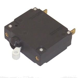
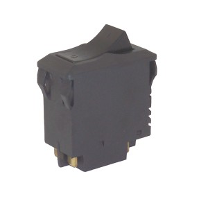
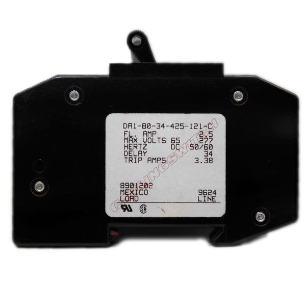
AC circuit breaker of the correct amperage. There are different
breaker packaging styles:
(photo 1,
photo 2, and
photo 3)... pick one that you like.
Or add a breaker to the DC side of the supply - boating supply houses like
West Marine and some RV supply houses stock 12vDC breakers. You can occasionally
buy a DC breaker or two from small aircraft maintenance shops - check your
local community airport as the repair shops occasionally have fuselages that
they scavenge parts from - but watch the voltage as some are 12 volt
and some are 24 volt. Do not be offended if they ask you to
sign a release as they won't want the liability of the part going back into aircraft
service, and no matter what you say, they can't be sure. And don't be offended
if they say that they can't touch that old fuselage in back - sometimes there
is a legal issue with an old airplane. The FBO (fixed base operator) at
the local community airport near where I lived had one stashed in the
weeds behind the hangar for several years. It had an FAA hold on it for
almost five years due to an accident investigation.
My RM-60 / RM-60M uses a 10 amp, 250V, ceramic body, slow-blow AC fuse.
The local parts house stocks it as a Buss (also known as Bussmann) MDA-10,
MDA-10R or MDA-10-R). The trailing R indicates RoHS construction (lead-free).
Littelfuse calls it a part number 326010, and some catalogs add a leading
zero (i.e. 0326010).
Eric Lemmon WB6FLY pointed out another problem with AC mains power
connectors:
The RS-70M power supply is marketed as being able to supply 57 amperes
continuously, and 70 amperes intermittently. The only problem with that
statement is that the measured AC input current exceeds 12 amperes
at loads above 50 amperes DC. Why is this important? Because
the RS-70M is shipped with a 12 amp fuse, and the fuse holder is marked
with that value. Twelve amperes happens to be the maximum current that
can be continuously drawn from a NEMA 5-15R outlet - the "standard" power
outlet found in homes. This 12 amp limit is specified in Article 210.21(B)(2)
of NFPA70, the USA National Electrical Code. This NEC limit is what caused
the "vacuum cleaner current wars" to top out at 12 amps of "cleaning
power." Since the common, parallel-blade plug used vacuum cleaners and
other home appliances is intended to plug into the standard NEMA 5-15R
receptacle, the appliance makers cannot legally market any product that
draws more than 12 amps and uses a 15 amp plug. Hence the 12 amp fuse
that is shipped in the Astron RS-70.
To amplify on what Eric mentioned the NEC states that circuits "rated" at
15, 20 or 30 amps are NOT DESIGNED TO HANDLE THAT AMPERAGE
CONTINUOUSLY. Only 80% of the rated load can be "continuous"
(which by the NEC definition is a load used more than 3 hours in a 24-hour period
with no other time specified for max single endurance) and the remaining 20% must
be "intermittent" (less than 3 hours in a 24 hour period.
Operating at full rating continuously will result in unacceptable heat in the cable
AND ANY CONNECTIONS.
The above 80% defination is why the 12 amp continuous limit on a
15 amp circuit exists (and likewise 16 amps continuous on
a 20 amp circuit).
Note that while Eric mentions the RS-70 / RS-70M, the same is true on
the VS-70 / VS-70M.
So what do the owners of the RS-70 / RS-70M / VS-70 / VS-70M
supplies do?
Since those supplies draw about 16 amps from the power line (Eric measured 15.82 amps)
under a full 70 amp load you need to replace the power cord with a 3 conductor
#12 AWG (minimum) line cord terminated with a 20 amp NEMA 5-20P
plug and that needs to plug into a 20 amp NEMA 5-20 outlet (and you need to
check that the wire inside the walls is at least #12 AWG if not larger! I've seen situations
where someone replaced the 15 amp duplex outlet with a 20 amp outlet and didn't
upgrade the wiring... I've also seen situations where a homeowner added a circuit on his own
and used #14 wire - which per the NEC is maxed out at 15 amps (and 14 gauge wire is
also illegal on outlet circuits in most jurisdictions).
Note that a NEMA 5-20 (20 amp) receptacle (one with one horizontal flat blade, one vertical
flat blade, and a round ground). And that outlet MUST be fed with at least 12AWG or larger
wire (capable of carrying a 20 amp load). To obtain 20 amps from that outlet you MUST use
a 5-20 plug! You may have 20 amps available, but you can only pull 16 amps continuous.
Summary: The RS-70 really needs a 20 amp fuse, cord and plug, and 12 gauge
(or larger) wire all the way to the power panel.
Diagrams and photos of the various NEMA outlets can be found at this web site:
https://www.stayonline.com/product-resources/nema-straight-blade-reference-chart.asp.
Contact Information:
The author, Mike Morris WA6ILQ, can be contacted here.
Back to the top of the page
Back to Astron Intro page
Back to Astron Index page
Back to Home
This page originally created in August 2000 by Kevin Custer W3KKC.
Totally rewritten (and lots of material added) on 14-Oct-2004 by Mike Morris WA6ILQ.
Split into several pieces 13-Jan-2018 by Robert W. Meister WA1MIK.
Copyright © 2000 and and date of last update by Repeater-Builder.com and Mike Morris WA6ILQ.
This web page, the hand-coded HTML on it, this web site, the information presented
in and on its pages and in these modifications and conversions is © Copyrighted
1995 and (date of last update) by Kevin Custer W3KKC and multiple originating authors.
All Rights Reserved, including that of paper and web publication elsewhere.
