Back to Home
Astron 14V Linear Power Supplies
By Robert W. Meister WA1MIK

|
Up one level (Astron index) Back to Home |
Adding Digital Metering to Astron 14V Linear Power Supplies By Robert W. Meister WA1MIK |
|
There are already articles on the web and repeater-builder about replacing the analog meters with digital meters, or just adding digital meters to those supplies that never had any. This article presents some things to think about when selecting a digital panel meter for use in an Astron linear power supply, and things you need to be aware of when actually hooking them up. It's a long article and I wrote it to actually teach you something (what a terrific concept). If you don't want to learn, you might as well stop reading it right here.
Due to the variety of current ratings (3-70 amps) and zero, one, or two meters, it is not possible to present one single good solution. I do, however, give you enough theoretical and practical information to make informed decisions and do the job yourself. I did not actually install any meters into my own power supplies; either they already have them (RS35M) or they won't fit (SL-series). I did use these supplies to test the various meter configurations.
This article is primarily concerned with Astron's 14V linear power supplies. Astron also makes 28V power supplies that are similar in design. As most digital panel meters only go up to an indication of 1999, you'd need to set it for 200V full scale if you wanted to use one with one of these supplies, or scaled down with an appropriately adjusted potentiometer.
Click on any of the images below for a larger view.
Power Supply Configurations:
Astron power supplies come in three configurations:
The Astron analog meter movements are always 1 mA DC. This gives them a sensitivity of 1000 ohms per volt, which means if you add a 20k resistor in series, the meter will indicate approximately 20 volts full scale. With a 1k resistor in series, the meter will indicate about 1 volt full scale.
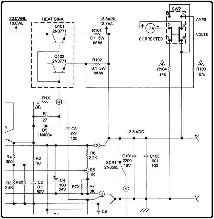
The smaller supplies tended to have a single meter, because there just wasn't enough space on the front panel for two meters. The larger supplies such as the RS-35M and bigger, traditionally had two meters but I've seen some with one meter and a switch. Here's a schematic of the single metering circuit from an RS-12M. For current measurement, the meter is measuring the voltage drop across R102. Note that the schematic below has been corrected; the diagram in some Astron schematics is wrong.
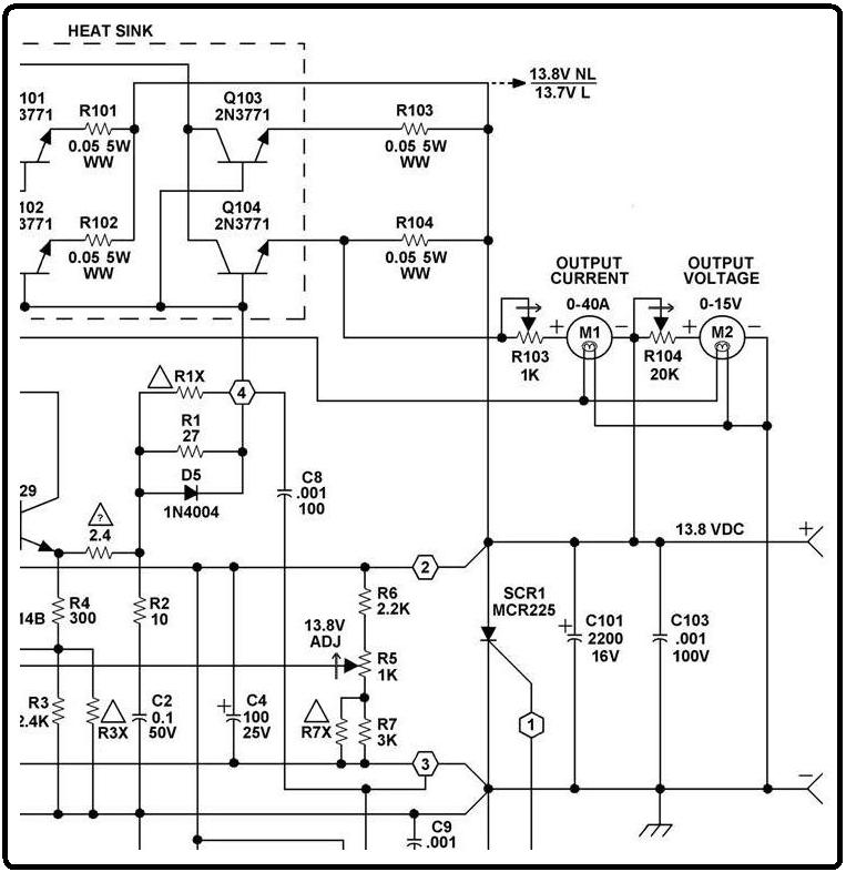
Here's a schematic of the dual metering circuit from an RS-35M. Voltage is always measured across the power supply's output terminals. For current measurement, the meter measures the voltage drop across R104.
How Astron Power Supplies Measure Current:
Astron power supply current meters actually measure the voltage drop across one of several series-pass transistor emitter-balancing resistors. These are 5-watt wire-wound resistors of either 0.05 or 0.1 ohms that are used to balance the load current among the multiple series-pass transistors that regulate the output voltage. These are usually white or sand colored and about 3/8 inch square by one inch long. One end goes to the emitter terminal of each series-pass transistor on the heat sink; the other end goes to a common output bus that makes its way to the positive output lead of the power supply. The table below lists the number of resistors, their values in ohms, the approximate current per resistor in amps, the approximate voltage drop across any single resistor, and the power dissipated by that resistor in Watts for several Astron power supply models. This information was obtained from Astron schematic diagrams.
| Model | # | Value | Cur | Drop | Pwr |
|---|---|---|---|---|---|
| RS-10 | 1 | 0.05 | 10.0 | 0.50V | 5.0 |
| SL-11 | 2 | 0.10 | 5.5 | 0.55V | 3.0 |
| RS-12 | 2 | 0.10 | 6.0 | 0.60V | 3.6 |
| SL-15 | 2 | 0.10 | 7.5 | 0.75V | 5.6 |
| RS-20 | 2 | 0.10 | 10.0 | 1.00V | 10.0 |
| RS-35 | 4 | 0.05 | 8.8 | 0.44V | 3.8 |
| RS-50 | 8 | 0.05 | 6.3 | 0.31V | 2.0 |
| RS-60 | 8 | 0.05 | 7.5 | 0.38V | 2.8 |
| RS-70 | 8 | 0.05 | 8.8 | 0.44V | 3.8 |
After reviewing the data above, it's obvious that the SL-15 and RS-20 really should be using two 0.05 Ohm resistors to keep the power dissipation below 5 Watts per resistor; this is just one of the many design errors and inconsistencies present in Astron's linear power supply products.
Astron's RS-3, RS-4, and RS-7 power supplies have only one series-pass transistor, thus they don't have any emitter balancing resistors. You could add a 0.1 Ohm, 5-watt resistor in series with the emitter lead, in a manner similar to all the other supplies, if you really wanted to measure the load current on such a unit.
As you can see, the voltage drop across any one of the emitter-balancing resistors ranges from 0.3V to 1.0V for the maximum rated current. A 200mVDC digital panel meter with an appropriate voltage divider at the input (two resistors or a 100-1000 ohm pot) can easily be added to adjust the meter to give you an accurate current indication.
Stock Single Meter Power Supplies:
On these supplies, the meter goes to a DPDT toggle or rocker switch that selects either volts or amps. The switch is wired to put the meter across the positive and negative output leads of the power supply to measure voltage, or across one of the series-pass transistor emitter balancing resistors to measure current. Fixed value meter calibration resistors are wired in series with the switch terminals. For some reason Astron did away with the calibration pots in the single meter supplies, however you could easily replace the fixed resistors with appropriate value pots, if calibration is ever needed. Neither meter terminal goes directly to the power supply output leads; both terminals run through the switch.
Another item to think about is that the 1 mA meter Astron uses can have dual scales such as 0-15V and 0-70A, without worrying about a decimal point. Digital panel meters usually are configured for 200 mV full scale and you have to decide where to put the decimal point, so the meter displays 1.999, 19.99, or 199.9 and you interpret it as needed. Given the choice I'd rather have two meters, however the voltage regulation of Astron supplies is very good, so the voltage usually won't vary unless the load current is excessive. Of course on supplies with front panel adjustment pots (VS-series), you would probably want two meters.
Stock Dual Meter Power Supplies:
On these supplies, the voltmeter just measures the output voltage of the supply. The positive terminal of the meter and a 20k potentiometer are wired in series and connect to the positive output lead of the power supply. The pot, when set to about 15k ohms, calibrates the meter to indicate 15VDC full scale. The negative terminal of the meter goes to the negative/ground output lead of the power supply.
The ammeter measures the voltage across one of the series-pass transistor emitter balancing resistors, as described above. The voltage across one of these resistors is around 0.3-1.0V at rated output and the pot is set to a value between about 300 to 1000 ohms. Theoretically the output current will be equally divided among all of the series-pass transistors and the voltage across any resistor will be 1/2, 1/4, or 1/8 of the total load current depending on whether there are 2, 4, or 8 series-pass transistors in use. The negative input terminal of the meter goes to the positive output lead of the power supply, while the positive input terminal of the meter is wired in series with a 1k potentiometer and connects to one of the series-pass transistor emitters, so it is across one of the emitter balancing resistors. Note that neither meter terminal goes to the power supply negative/ground lead.
Digital Panel Meter Options:
There are several meter parameters or types you can choose from:
I have seen some meters that let you choose 5V/grounded or 9V/ungrounded operation, however it is not known whether you can ground the negative input terminal when operating in the ungrounded configuration, or if you can choose 5V and change the settings to ungrounded operation. It seems that most meters won't let either input lead exceed the supply voltage in either direction.
There is also a completely new breed of digital panel meters being sold now, mostly from Asia. LED, one or two colors, two lines: one measures 5-30 VDC, the other measures 0-10, 0-20, or 0-50 ADC. The 50A meters need external shunts, sometimes sold separately (50A/75mV). The entire device usually costs under $15. Some run with three wires (common ground, input voltage, current sample), others with five (they require a separate power source, often isolated). LED colors can be red, green, or blue. Some of these are VERY tiny (1 inch by 1/2 inch). You could connect one of these to any Astron supply rated for 50A or less by mounting the current shunt outside of the supply. I won't cover these products but I see no reason why they can't do the job just as good as some of the LCD meters I've played with. Search the web for "dual display led meter" and you'll find plenty to choose from, shipping from Asia or the US. These can also be purchased at many radio supply houses.
Digital Panel Meter Decimal Points:
These 3-1/2 digit meters can display up to 1999. You can have a decimal point after the first digit, second digit, or third digit, so the meter would display 1.999, 19.99, or 199.9 as a maximum value. Some even offer a negative sign ahead of the first digit, but for our purposes, we're always measuring a positive voltage. The position of the decimal point has no effect on the maximum input voltage, or vice versa. You need to select both the decimal point and any scaling resistors.
For the voltmeter, you'd want two digits after the decimal point so the meter would display up to 19.99 volts. The ammeter is a bit more of an issue. It depends on the current rating of the supply. For up to 20A, you could select 19.99 as a maximum. For anything higher you'd need to select 199.9 as a maximum. These meters don't offer an automatic decimal point or automatic ranging circuit.
If your supply has only one meter and it needs to do display both volts and amps, you either have to choose 19.99 for the maximum or consider replacing the meter select switch so it can move the decimal point as needed for volts or current.
Remember that most simple meters measure 200 millivolts DC full scale so you will have to adjust input scaling resistors or utilize a pot ahead of the meter to reduce the input signal amplitude to a value appropriate for the meter.
Single Meter Supply Solutions and Workarounds:
Because a DPDT meter select switch already exists, you're pretty much stuck with using an isolated supply for the meter, because you can't switch all four power and input signals. You'll have to set the meter for 200 mV full-scale and use two adjustment pots to calibrate the meter for both volts and amps. You would probably have to choose one setting for one, two, or three digits after the decimal point, depending on what you want it to display.
If your supply has no meter, you could install a 5V/grounded meter and 4PDT toggle switch, which would let you switch all four power and metering inputs. If you use a center-off switch, you can even turn the meter off when you don't want it. You could also use a multi-pole rotary switch to move the meter's power and input between volts and amps and also select the appropriate decimal point position.
Dual Meter Supply Solutions and Workarounds:
The voltmeter connection is straightforward. Use a 5V meter. Connect its negative input and negative power input lines directly to the Astron's negative power output lead. The meter's positive input goes to the Astron's positive power output lead, with the meter configured for 20V full scale. Power comes from an LM7805 3-terminal regulator connected in the normal configuration with the tab grounded, or an LM78L05 if you're using an LCD meter that only draws 1 mA.
For the ammeter, you need to connect the meter's negative input lead to the Astron's positive power output lead. This means you must either have a meter that lets you separate the negative input lead from the negative power input lead and use a floating power supply, or you need to raise the supply voltage feeding the meter such that the negative power input lead can rest on the supply's positive power lead. The meter would need to be set for 200 mV full-scale and a separate adjustment pot would be used to calibrate the digital meter according to the power supply load current.
One way to use 5V/grounded meters is to build an isolated 5V supply that lets you elevate the meter's negative leads up onto the Astron's positive output lead. There are DC-DC converters that provide this isolation, or you can make your own with an NE555 timer IC, a transformer, and a few diodes and other passive parts. Even a small wall-wart power supply could be stuffed into the Astron power supply and made to work. The other articles on this web site use this method. Once you choose to use an isolated power source, you can use either a 5V or 9V digital panel meter.
Alternatively, you could use an LM7805 3-terminal regulator or an LM78L05 if you're using an LCD meter that only draws 1 mA. Connect its ground lead to the Astron's positive output lead, connect its input lead to the 29V supply that runs the 723 regulator, and connect its output lead to the 5V meter power input, with the negative leads to the Astron's positive output lead. Use the appropriate bypass capacitors around the regulator and DO NOT mechanically ground the tab on the LM7805; it must be left insulated because it's now sitting at +13.8VDC. This is not a concern if you're using an LM78L05 because it doesn't have a tab. The schematic below shows this configuration for the ammeter:
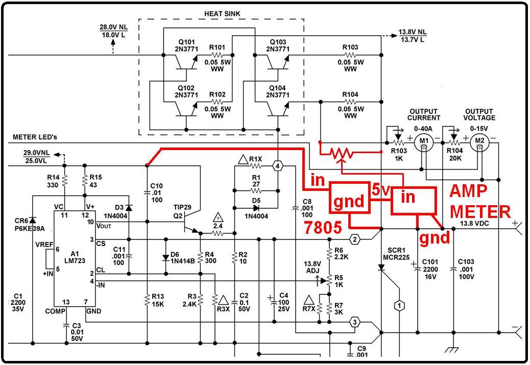
This configuration is perfect for those meters that use 5V supplies with a common meter input.
You can also use a 9V floating supply and a 9V digital panel meter. Just use a separate power supply for each meter as their input grounds are at different potentials.
Metering Alternatives:
Some of the digital panel meters, mostly the 5V varieties, require you to connect their power input and meter input to a common ground. Measuring the power supply output voltage is never a problem as it always references ground. To measure the load current with a common ground meter, you just need to provide a low-value resistance in series with the grounded lead of the load so you can measure the voltage drop across it, and using Ohm's Law, figure out the actual load current. There are devices called "meter shunts" that are made just for this purpose. They have two high-current terminals: one goes to the supply, one goes to the load, and two metering terminals that go to the meter, with one side going to the same ground as the meter's negative power lead. They usually are not inexpensive, but you could make a similar shunt yourself out of a length of wire capable of carrying the desired load current. The best place to install a meter shunt is inside the Astron power supply, in series with the negative output stud of the power supply. This is not so easy to do, but it can be done. Given the difficulty, I'd try to go with one of the choices shown above.
Floating Power Supplies:
Here are two floating power supplies designed around the 555 timer IC. This one (17 kB PDF file) uses a small transformer to provide the isolation for the current meter. The schematic also shows a simple 3-terminal regulator for the voltage meter. This isolated supply would be suitable for use with either the single or dual meter power supplies. You need a separate power supply for each meter however. You can use either 5V or 9V meters as long as the 3-terminal regulator or zener diode is appropriately selected.
This one (66 kB PDF file) uses capacitors instead of a transformer to provide the isolation. It uses less parts and should work just as good as the transformer variety. You could utilize one 555 and duplicate everything to its right (capacitors and diodes) to provide separate isolated outputs for each meter. You can use either 5V or 9V meters.
These LCD meters draw very little current, around 1mA. The circuitry required to isolate and boost the voltage to run these meters is minimal and construction is not critical. You could even run a meter on a common 9V battery for a couple hundred hours if you wanted.
I built the capacitor-isolated circuit on a breadboard using whatever parts I had on hand. The 555 IC oscillates at about 40 kHz and it draws about 10 mA just by itself. With 12VDC input, the circuit produces 9.25VDC output with the meter connected. (With 9VDC input, the circuit provides 6.25VDC output, which is just a bit too low. With 15VDC input, the circuit provides 12.3VDC output, which is just a bit too high.) A 9V meter will operate on 7-11 volts so the lack of voltage regulation is not a problem. You can still use an LM78L05 regulator and a 5V meter. The schematic can be found below.
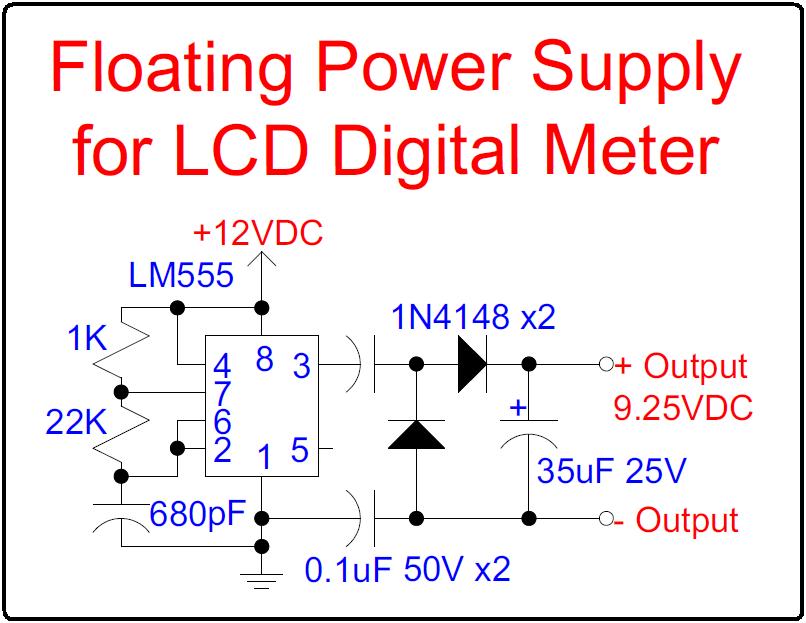
If you make a floating power supply with a 555 timer, remember that the output voltage will be related to the input voltage, and that the 555 has a maximum supply voltage of 15VDC. Use a 12V 3-terminal regulator on the input. Use a 5V regulator or zener diode on the output with a 5V meter.
Experimenting with Popular Meters:
I purchased a generic PM-128 and a PM-128E panel meter from Marlin P. Jones and Associates www.mpja.com for about $9 each. Both are self-contained LCD meters without illumination, and they don't need it.
The documentation that came with the PM-128, as well as what I could find on the web, was horrible, and has been reproduced here as a 55 kB PDF file. I retyped and corrected this document, which can be found here as a 45 kB PDF file. The PM-128 runs on 9V, measures 200 mVDC, and the supply and input grounds must be kept separate. The back of the meter is silk-screened, however there were no detailed photos or diagrams, so I took my own. Here's a photo of the back of the unit.

The input voltage scaling resistors RA and RB are along the top edge of the board. The default resistors are just a wire jumper for RA, and nothing for RB, giving the meter its basic 200 mVDC sensitivity. The decimal point configuration holes are labeled P1, P2, and P3 at the right side. Placing a short circuit across any single pair of holes activates the appropriate decimal point: P3 displays three digits after the decimal point (X.XXX), etc. There's also an unlabeled jumper position mentioned in the original documentation (N) that activates the polarity indicator, below the holes for P3, but a foil jumper is already present (you can follow that trace to the big IC socket pin 20, bottom right corner of the photo); see the PM-128E meter documentation below for better details. You should never get a negative indication on any meter attached to an Astron power supply, so this jumper can be ignored.
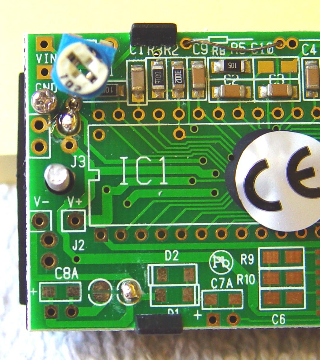
Here's a close-up of the left half of the meter circuit board, showing the input points, which are partially hidden by the input calibration pot, as well as some configuration jumpers (solder blobs) that deal with the power supply and input negative connections, probably so they can use different ICs.
This meter uses an Intersil ICL7106 3-1/2 digit LCD/LED meter IC, which is designed to run on an isolated 9V battery. A data sheet can be found here as a 535 kB PDF file. Due to the way the internal reference voltage is generated, the input common pin must not be connected to the power supply ground, so meters using this chip MUST utilize a floating/ungrounded 7-11 volt power source. In fact the meter's common input pin will be about 3 volts below the positive power input pin. The meter will work in either the single or dual meter power supplies, but you may have to play with the decimal point.
The documentation I found for the PM-128E was great and can be found here as a 640 kB PDF file. The PM-128E can be configured for AC or DC volts in several ranges, or 200 mADC, and you can choose either a 5V grounded or 9V ungrounded power source. They just use a simple diode rectifier to convert the AC volts to DC volts, and there's a low-value resistor they use to convert the DC current value to a voltage. I configured mine for a 5V grounded power source.
To test this meter to measure current, I opened my RS35M and took some measurements. The point marked 29.0VNL (Volts Not Loaded) / 25.0VL (Volts Loaded) measured 27.6VNL and 21.8VL. As long as it's 7 volts higher than the supply's output voltage at the worst case (maximum load), the 3-terminal regulator will be happy. I also measured the voltage across one of the 0.05-ohm emitter balancing resistors. I saw 0.125V at 10A of current and 0.490V at 40A of current.
I followed the diagram above for the floating ammeter in the "Dual Meter Supply" section above. The 5V meter is powered by a 78L05 that gets powered by the supply that runs the LM723 regulator IC, marked 29.0VNL / 25.0VL on the schematic. The common ground is connected to the large bare wire that all of the 0.05-ohm emitter balancing resistors go to. Since the voltage across any of these resistors would be around 0.5V at maximum current, I configured the meter for a 2VDC maximum range and one decimal point. I used a 2K potentiometer across one easily reached resistor to adjust the LCD meter to agree with the actual current. This setup gives a maximum indicated current of 199.9A but on an RS35 you're limited to about 40A, so the realistic maximum current is 040.0A. You may have to pick a different voltage range and decimal point setting for other power supplies.
To use this meter to measure voltage, the same 78L05 regulator is used and it gets power from the same point. The common ground goes to the negative (ground) output terminal of the power supply. The meter's input goes directly to the positive output terminal of the power supply. The meter is configured for a 20VDC maximum range and two decimal points. This gives a maximum indicated voltage of 19.99V, perfect for any 14V Astron power supply. You can use one meter and regulator for both purposes; just switch the input and ground leads with a DPDT switch. Use a 4PDT switch if you also need to alter the decimal point position.
Other Things To Watch Out For:
Many Astron power supplies connect the negative output terminal to chassis ground. Some people like this, others don't. I personally don't care either way, but if you choose to install a meter shunt in series with the negative power lead, you need to be aware of this connection and possibly disconnect it. On some supplies it's a green or green/yellow wire connected to the negative output lead with a crimp lug at the other end that attaches to one of the screws going through the chassis.
Physically Installing The Meter:
I've purposely avoided this topic, and like so many school textbooks would say, I "leave this as an exercise for the student." All meters are different sizes and have unique methods of attachment to a panel. If you're replacing existing meters, you might not find digital panel meters that are exactly the same size as the analog meters Astron used, so you may have to mount them to another piece of metal first, then mount that to the front of the Astron supply. If you're installing new meter(s), you'll have to cut an opening in the front of the power supply. Make sure you protect the electronic components inside the power supply and also vacuum out any metal chips that may end up inside the unit, before you install the digital panel meters. You can use any sort of switch you want if you choose a single meter solution: toggle, rocker, rotary, slide, etc. A miniature toggle switch is the easiest to install, as it only needs a single 1/4-inch hole.
Recommendations:
For a single meter supply, I'd recommend constructing a floating power supply and using a 9V digital panel meter. The meter can be switched between voltage and current using a simple DPDT switch, and if you'll be replacing an existing analog meter, this would be the simplest method. You'll need to add some calibrating resistors and adjustment pots to reduce the metered voltage to less than 200 mVDC. Set the decimal point for two digits (P2) giving you a maximum indication of 19.99 volts or amps. If your supply is capable of more current, you'll have to move the decimal point from P2 to P1 so the meter displays 199.9 volts or amps. If you're installing your own switch, a 4PDT version will allow you to have a different decimal point position for volts or amps.
For a dual meter supply, I'd recommend using 5V digital panel meters, each with its own LM78L05 regulator. For the voltmeter, connect the meter input and power input to the Astron's negative/ground terminal and use the 29V power rail to feed the 3-terminal regulator. For the ammeter, connect the meter input common and power input common to the Astron's positive terminal and use the 29V power rail to feed the 3-terminal regulator. You should be able to configure the voltmeter for 200 mVDC or 2 VDC full-scale and set the decimal point for two digits (P2, for 19.99 amps) or one digit (P1, for 199.9 amps). You'll need some calibrating resistors and adjustment pots for the ammeter to reduce the voltage at the meter input to less than 200 mVDC.
The reason I've told you to use the 29V power rail inside the Astron, is because the voltage on the high current 22-24V rail that feeds the series-pass transistors can drop low enough that the voltage across those transistors could go lower than the 3-terminal regulator requires for proper operation. In the case of a 9V regulator, it would need about 11V of input. On an Astron supply set for 14V output, the voltage on the 22-24V rail probably won't always be at 25V or higher, especially at higher load currents. The 29V rail, on the other hand, will always exceed the 14V output by a sufficient amount to operate any 3-terminal regulator.
Contact Information:
The author can be contacted at: his-callsign [ at ] comcast [ dot ] net.
Back to the top of the page
Up one level (Astron index)
Back to Home
This page originally composed on 31-Mar-2014.
Diagrams, photos, layout, and hand-coded HTML © Copyright 2014 and date of last update by Robert W. Meister.
This web page, this web site, the information presented in and on its pages and in these modifications and conversions is © Copyrighted 1995 and (date of last update) by Kevin Custer W3KKC and multiple originating authors. All Rights Reserved, including that of paper and web publication elsewhere.