Back to Home
to an Astron Linear Power Supply
By Robert W. Meister WA1MIK (SK)
Maintained by Mike Morris WA6ILQ

|
Up one level (Astron index) Back to Home |
Adding an Inrush Current Reducer to an Astron Linear Power Supply By Robert W. Meister WA1MIK (SK) Maintained by Mike Morris WA6ILQ |
|
Those of you who own large (500 watt and higher) Astron linear power supplies, and even large HF amplifiers, know all too well that "GNNNNnng" sound that they often make when turned on. This is due to the high inrush (surge) current flowing into the transformer when the filter capacitor is discharged. Depending on the size of the supply, this surge can exceed the rating of the circuit breaker on the outlet the supply is plugged into, but as it's so brief, the fuse on the back of the supply rarely blows during these surges. There are several ways to prevent this inrush surge:
I opted for choice #3 above. I purchased some 2.5 ohm 11 amp devices from Mouser, part number 871-B57364S259M, for about $2US each. Digikey has them as well, part number 495-3063-ND. I had also purchased some five-lug terminal strips for another project, Mouser part number 158-1005, for about $1US each, and used one of these in my Astron RS-35M power supply. A few inches of #16 stranded hookup wire completed the job. I modified an older supply, one that has the line cord permanently attached. You may have to alter the procedure a bit if yours is newer and has the IEC input connector. You may also have to choose a slightly different thermistor depending on the current rating of your power supply. You would want something in the 2.5-5 ohm (cold) range that can handle 11-15A of current; 10% or 20% tolerance is fine. You should use a lower resistance value for a higher capacity power supply because you don't want a lot of voltage to be dropped across the device when the supply is fully loaded.
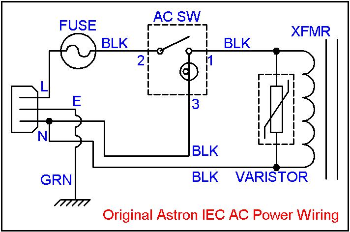
The original Astron linear power supply primary (AC input) wiring is shown in the diagram below. The thermistor should be installed between the fuse and the power switch.

Here's a step-by-step procedure for adding the thermistor inside the supply.
I'll identify the lugs and holes of the terminal strip by numbers: 1 through 5, going from left to right, with the mounting hole facing away from you. The lugs stick up above the phenolic strip; the holes are in the middle of the phenolic strip. The terminal strip will be mounted in the existing hole in the chassis with lug 1 toward the rear of the power supply. Now proceed with the reassembly.
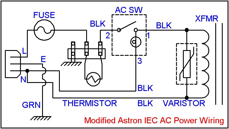
The modified Astron linear power supply primary (AC input) wiring is shown in the diagram below.
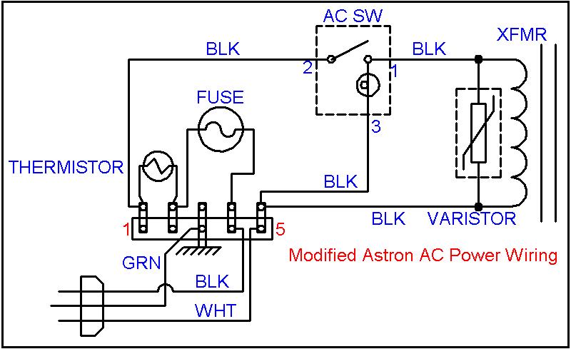
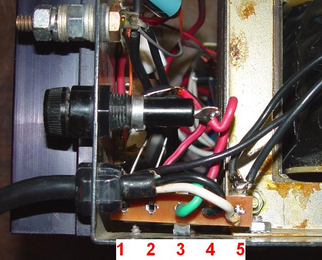
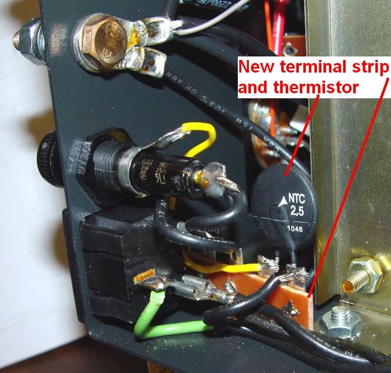
Here's a photo from the left side looking at all the AC wiring. The terminal strip lugs are numbered.
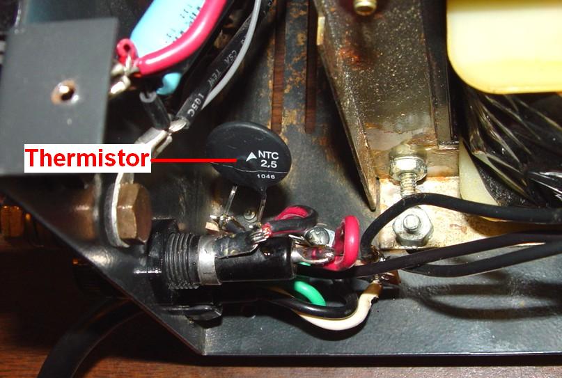
Here's a photo looking down into the AC wiring. The thermistor has been identified. You can't see too much of the terminal strip in this shot.
One reader suggested that I could have just lifted one wire off the fuse holder and installed the thermistor in series with it, but that would have left the thermistor supported by just one lead, and I didn't think that was acceptable. Since I had the terminal strip, I unwired everything and built it back up fresh. Alter the procedure if circumstances warrant it.
Inspect your work. Make sure the wires all run nicely and won't touch the cabinet when you reassemble the power supply. Position the thermistor away from everything, as it will get hot. Use an ohmmeter and verify the following conditions:
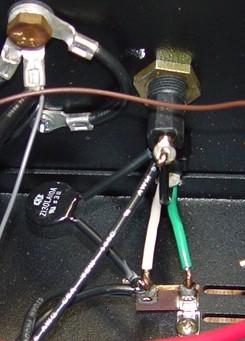
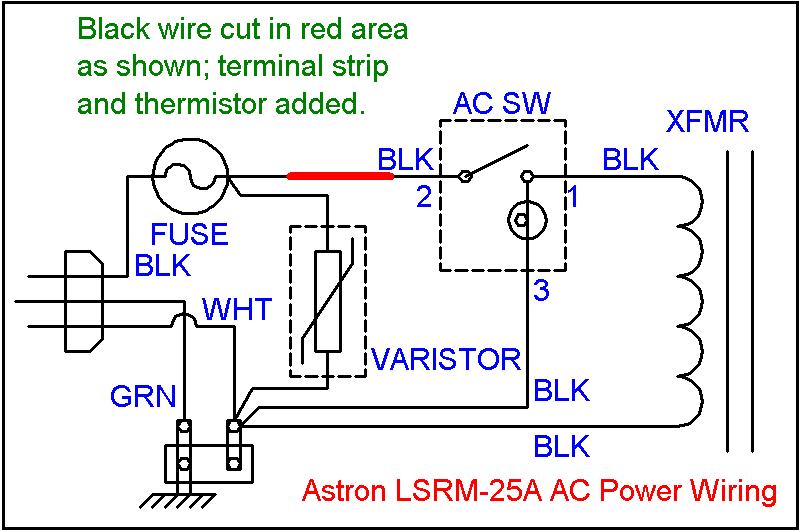
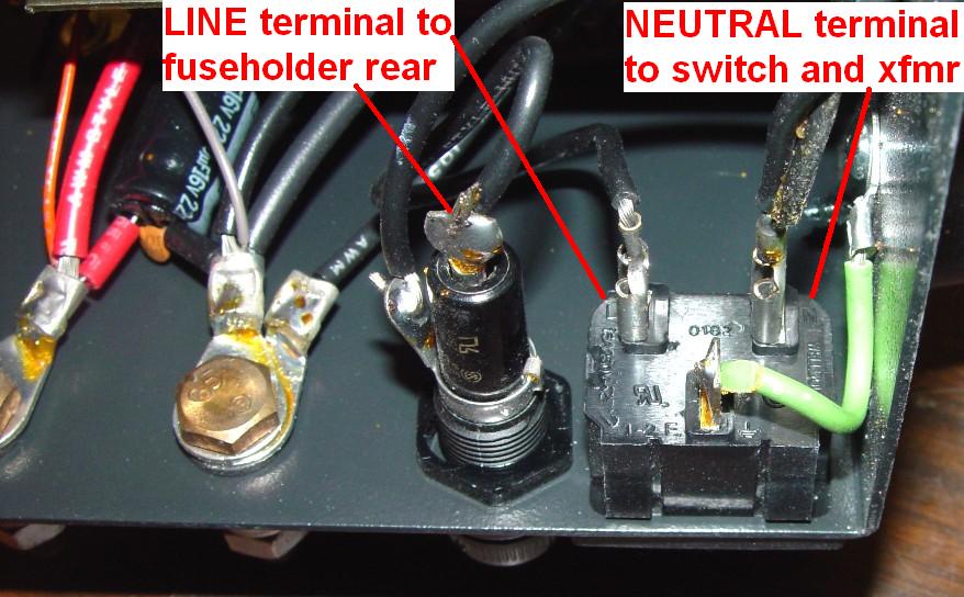
I also modified an Astron LSRM-25A (28 volt, 25A) supply, which also had a permanently attached power cord. The AC input was wired a bit differently: the varistor was installed at the fuse holder rather than at the transformer, but there was still the same two-lug terminal strip mounted near the line cord to deal with the ground and white power wires. I didn't have to modify the AC input wiring since there was plenty of room inside the unit. I installed an additional terminal strip (although I only used two lugs on it), cut the black wire between the fuse and the power switch, and installed the thermistor in series. This photo shows the original AC input area. The AC line cord connects to the rear of the fuse holder and the terminal strip below it.
Here's the schematic of this supply. The wire going from the fuse holder to the power switch's middle terminal (2) got cut where indicated (red color on the wire) and the thermistor was inserted where the wire had been cut. Note that this schematic is for the LSRM-25A (28 volt supply), which differs from the 14 volt supplies.
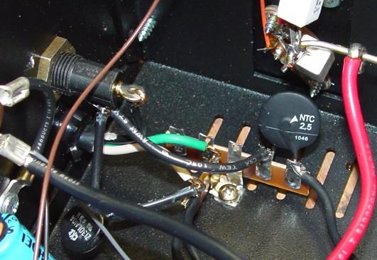
Here's a photo of the completed modification. The new terminal strip utilized the same hardware and hole as the existing strip. I soldered the wires to two lugs of the new strip and used the respective holes for the thermistor. I positioned it over the ventilation slots in the bottom of the cabinet since this device can get hot.
I modified a newer RS35M that had an IEC AC input power connector on the rear. There was no terminal strip present but the wiring was much easier to deal with. The LINE, NEUTRAL, and EARTH terminals are well marked and you only need to deal with the LINE terminal, which goes directly to the rear contact of the fuse holder. The side contact of the fuse holder goes to the power switch then to the transformer primary. Here's what the IEC connector looks like. Note the "L", "N", and "E" markings.
Here's the schematic diagram of the stock power supply with the IEC connector:
The thermistor gets installed in series with the wire from fuse holder to the power switch, AFTER the fuse holder. Similar to the above procedure, I unsoldered the wire at the fuse holder, installed a terminal strip using the ground screw as a mounting point, added a new wire from the fuse holder to one lug of the terminal strip, connected the wire previously unsoldered to a second lug of the terminal strip, and installed the thermistor between the same two lugs. Modifying one of these IEC-equipped supplies is much easier than one with a hard-wired AC cord. Here's what the supply looks like when completed:
Here's the schematic diagram of the modified power supply with the IEC connector:
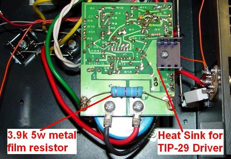
While I've got the supply open, I add a bleeder resistor across the main filter capacitor, a 3900 ohm, 5 watt metal film component, Mouser part number 286-3.9K-RC. I just solder it directly to the pads or holes at the outer edges of the regulator circuit board and let it sit about 1/16 inch above the board. It's pointed out in the photo below.
I recently acquired a relatively new VS20ML supply. This has an IEC-style power input receptacle with a built-in 5x20mm fuse. Remember to remove this internal fuse before you apply heat to the terminals. The rear of this receptacle has the usual 1/4 inch quick-disconnect tabs, and the wires are soldered on and run directly to the power switch. You may need to cut the wire going from the Line terminal to the switch terminal #2, or cut the push-on terminal off the wire and add one to a short piece of wire to run to the terminal strip that will hold the thermistor. In other words, get creative. You probably won't need to add the thermistor to a small supply like this one, but Astron could certainly use this type of input receptacle on larger supplies.
Calculations for the RS-50 Power Supplies:
One reader inquired about what thermistor to use for his RS-50 power supply. I suggested he contact the manufacturer. He did, and he was kind enough to forward the response to me, which has been posted below. Similar calculations could be performed for any other Astron linear power supply.
Calculations and Ametherm part number recommendation are shown below for your Astron RS-50A power supply.
Note: Energy rating of recommended ICL is sufficient for transformer and capacitor inrush current energy.
We recommend Ametherm part number MS32-10015. A data sheet can be found here. This part is UL Registered.
Install one MS32-10015 in series between mains power fusing and transformer primary.
Given (provided by customer):
(a) Astron RS-50A linear power supply faults trips line circuit breaker.
(b) Power supply contains 100,000µF capacitance.
(c) Maximum rated power output = 37 Amps steady state current at 13.8 Volts DC.
(d) Maximum allowable inrush current = 10A back panel "SLO BLO" fuse.
(e) Line voltage at input = 110VAC.Assumptions:
(a) Peak Voltage = 1.414 * (AC Voltage RMS).
(b) Inrush current for SQUARE transformer = 30 times the steady state current.
(c) Transformer rating = 1,000VA.
(d) Maximum surge current for SLO BLO fuse = 17x fuse rating.Our Calculations:
Peak voltage = 1.414 * 110 Volts AC = 155.51V.
Rated wattage = 37 Amps * 13.8 Volts DC = 500W.
Calculated steady state current = 1000VA / 110 Volts AC = 9.0 Amps.
Calculated SLO BLO fuse surge current = 17 * 10A =170 Amps.
Inrush current (transformer primary) = 30 * 9.0A = 270.0 Amps.
Inductive impedance Xl = peak voltage / inrush current = 155.51 Volts / 270.0 Amps = 0.575 Ohms.
Inductance L of transformer in henrys = Xl / 2 * pi * f = 0.575 Ohms / 376.99 = 0.0015 Henrys.
Transformer energy in joules that the thermistor needs to handle without self-destruction = 0.5 * L * (I^2) = 0.5 * 0.0015 H * (270.0 A^2) = 55.68 J.
Capacitor energy in joules that the thermistor needs to handle without self-destruction = 0.5 * (capacitance in farads) * (voltage squared) = 0.5 * 0.1 F * (13.8 V^2) = 9.5 J.
Zero power resistance that thermistor requires = peak voltage / maximum allowable inrush current = 155.57 Volts / 170.0 Amps = 0.91 ohms.Selection Criteria:
We have identified the main electrical parameters required for the inrush current limiter:
(a) Minimum zero power resistance = 10 ohms.
(b) Energy = 55.6J + 9.5J = 66 joules.
(c) Maximum steady state current = 10 Amps @ 110 Volts AC.Tony Chedester
Technical Customer Support
Ametherm Inc.
I plugged in the values for an RS-35A power supply, figuring 64,000uF, 120VAC, 8A fuse, and 25A continuous load current. I don't know where the minimum zero power resistance value of 10 ohms came from, but I used the same value. I got 60 joules and 8A steady state current. The eventual result was 1.25 ohms and 12 amps at full load for the RS-35A, which is an MS32-15012 product, rated for 15 ohms cold and 12 amps. My original choice probably works fine for an RS-35A or smaller supply.
Contact Information:
The author can be contacted at: his-callsign [ at ] comcast [ dot ] net.
Back to the top of the page
Up one level (Astron index)
Back to Home
This page originally posted on 11-Jul-2011
Diagrams, photos, layout, and hand-coded HTML © Copyright 2011 and date of last update by Robert W. Meister.
This web page, this web site, the information presented in and on its pages and in these modifications and conversions is © Copyrighted 1995 and (date of last update) by Kevin Custer W3KKC and multiple originating authors. All Rights Reserved, including that of paper and web publication elsewhere.