Back to Home
in an Old Astron Power Supply
By Tom Dailey WØEAJ
Photos by Robert Meister WA1MIK

|
Up one level (Astron index) Back to Home |
Installing a New Regulator Board in an Old Astron Power Supply By Tom Dailey WØEAJ Photos by Robert Meister WA1MIK |
|
I had a chap bring in an old RS-35M with a fried regulator board. While troubleshooting, I found out that Astron DOES sell replacement regulator boards, fully populated and ready to go for about $25US. Unfortunately, they've changed a few things from the earlier version supplies and boards as they made revisions to the design. The Astron technician I talked to made no mention of any of these differences, nor what I'd have to go through to replace the board in an older supply. He just sold me the board and I was stuck figuring out how to make it work in this supply. Here are some of the items I noticed:
These changes mean that the currently manufactured board is not a direct drop-in replacement for older units, without a few "alterations". The current design simplifies the board-to-chassis wiring considerably. The board gets raw DC and ground at the filter capacitor, has an AC input for the on-board regulator power, senses the voltage at the output terminals, and provides a drive signal for the pass transistors. Essentially, you have to bring the supply up to the current revision level to use the new board. Here's a photo of a 2002 vintage RS-35M power supply that shows the heat sink on top of the regulator board and how the board is mounted on top of the main filter capacitor:
Installing the New Board:
Here's what I had to go through to install the new regulator board.
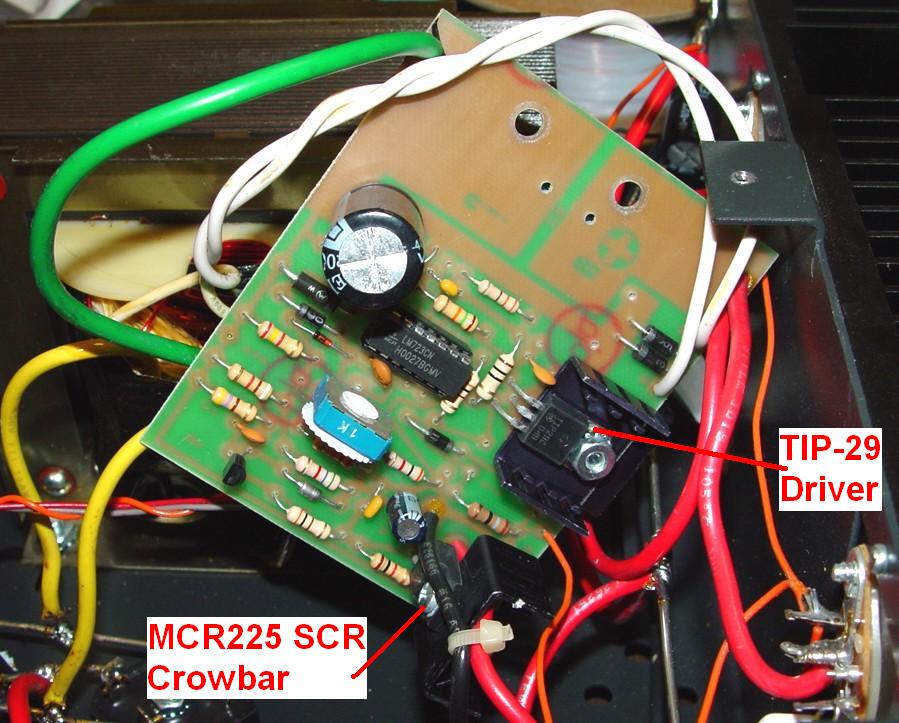
NOTE: Your supply MAY already have these wires. They simply run from the output terminals to pads on the regulator board. Look closely, and you'll see that the connection pads go to the correct terminals of the SCR (now mounted ON the board).
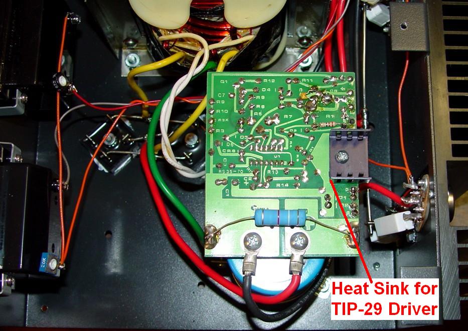
Here's a photo showing the component side of the new regulator board with the two heat sinked components identified.
You will also have to REMOVE the newly added heat sink atop the board. Astron must be using smaller (shorter) capacitors now, as the top portion of the new (two-piece) heat sink will protrude ABOVE the chassis, and you won't be able to install the top cover! I removed the top heat sink then ADDED additional heat sinking to the bottom portion; it is fairly close to the rear panel.
You will ALSO have to lengthen the board-mounting hole (toward the rear of the supply), as it DOES NOT "reach" across both mounting screws of the capacitor, as before. The board is set up for a capacitor with 7/8 inch spacing between the terminals.
Once I dealt with these changes - none of which is HUGE, just "a pain" - the supply worked properly. At this point, I put a good digital meter on the output, and adjusted the pot (under the regulator board) for a reading of 13.8 volts DC.
Contact Information:
The author can be contacted at: radio [at] daileyservices [dot] com
Back to the top of the page
Up one level (Astron index)
Back to Home
This page originally posted on 13-Apr-2012.
Article text © Copyright 2012 by Tom Dailey WØEAJ.
Photos and hand-coded HTML © Copyright 2012 and date of last update by
Robert W. Meister WA1MIK.
This web page, this web site, the information presented in and on its pages and in these modifications and conversions is © Copyrighted 1995 and (date of last update) by Kevin Custer W3KKC and multiple originating authors.