Back to Home
by Robert Schulz KC6UDS
Edited and put into repeater-builder
format by Mike Morris WA6ILQ

|
Up one level (Astron index) Back to Home |
Adding Anderson PowerPole Connectors to an Astron SS-25 or SS-30 power supply by Robert Schulz KC6UDS Edited and put into repeater-builder format by Mike Morris WA6ILQ |
|
Coment by Mike WA6ILQ:
Repeater-Builder.com was directed to the following article by an anonymous
email... and I want to thank the person who pointed us. This is a very
well done article, and I'm going to do this mod to MY Astron SS series
power supplies.
I've done three of these conversions now, and it works very well. You keep the stock setscrew power connectors, and add four Anderson PowerPole connections.
As with all projects of this sort, consider yourself warned that you do this at your own risk, it probably voids the warranty, it could cause damage to the power supply, the equipment attached to the power supply, and surrounding property, and all sorts of other disclaimer-type warnings. So: You Have Been Warned!
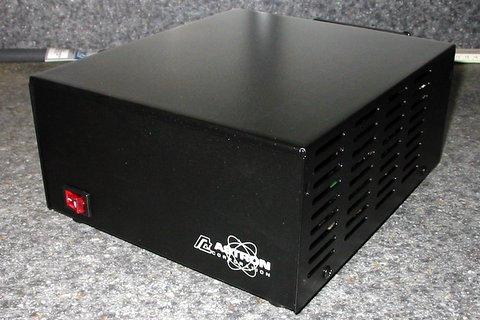
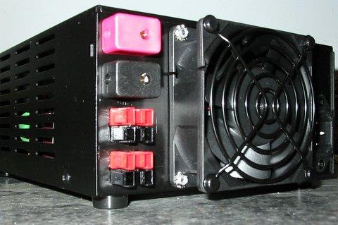
Here is a picture of an SS-30 power supply. The SS-25 looks the same except
it is narrower. This mod applies to both, plus it makes no difference if the
supply has the front panel meters or not:
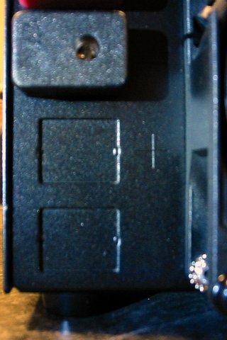
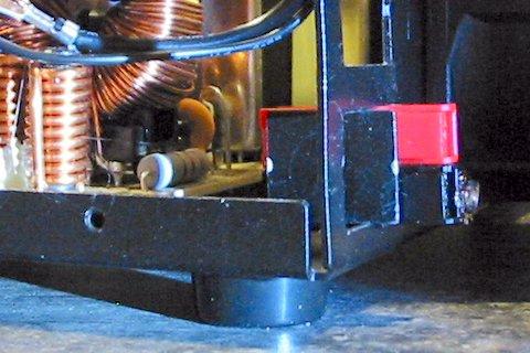
If you look on the back, below the stock power connections, you will see two
knockouts, obviously intended for a second pair of the setscrew connectors
(sorry, this picture is a touch blurry):
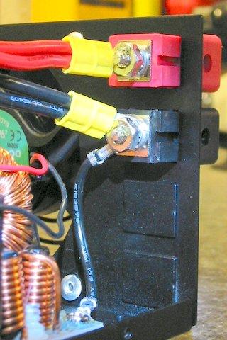
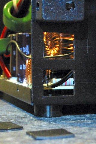
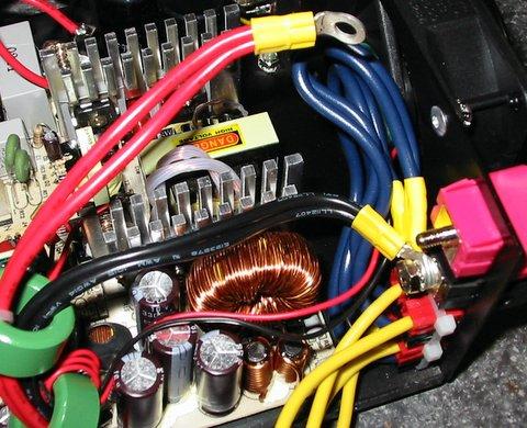
Removing the cover (you have the power supply unplugged, right?), here is the
view from the inside:
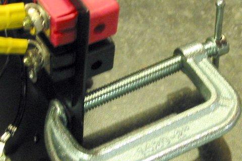
The first step is to remove the knockouts. I haven't figured out the best way
of doing this yet - I've used pliers, a screwdriver and hammer, and this time, a
C-Clamp. Your goal is to crack loose and remove the knockouts without bending the
back panel. If you look carefully, you can see that there won't be a lot
of metal there when you remove the knockouts. I worked the C-clamp gently
back-and-forth until the knockouts snapped out. It took a little patience, and I
slightly bent the panel, but was able to bend it back into shape. (again,
picture is a little blurry):
When you remove the knockouts, KEEP THEM! You will use the little metal
rectangles as spacers later in the installation. Here is a picture with the
knockouts removed:
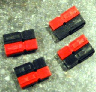
At this point, you will need 4 pairs of Anderson PowerPole housings:
Comment from WA6ILQ:
Note that the 15, 30 and 45 amp Powerpole connectors all use the same housings
(the part number and name is "PP15 insulating shells"). The internal terminals
are silver plated. As there is no way to know what load you will be plugging
into any particular Powerpole connector, I suggest that you use the 45 amp
contacts (part number "201G1H") exclusively when implementing this modification.
You can use the lower rated contacts on the radios or other loads that you plug
into the supply. The current carrying capacity of such a connection is, of course,
limited by the smaller of the two mating terminals, it's best that the "weaker"
be the load rather than the supply. The housings and contacts can be purchased
from several vendors, including Powerwerx.
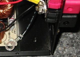
Looking into the power supply, you will notice a short black wire connecting
the black setscrew connector to a mounting screw for the circuit board (i.e.
chassis ground). Remove the circuit board mounting screw to temporarliy free up
the black wire. It is much easier to install the powerpole housings when you
can relocate this chassis ground wire out of the way and make some work space:
Starting with the lower hole, insert the first set of powerpole housings. If you start with the upper hole, the powerpole housings will be in the way when you go to install the lower hole powerpole housings. I don't think it really matters which way you install the connectors (black on top, red on top, whatever), as long as you put all four pairs in the same way. Since the original setscrew connections had red on top, I matched that. With a little work, you can snap the first pair of connectors into the hole. You want the edge of the metal hole resting in the half-circle indentations on the sides of the connectors. If you have trouble getting the powerpole housings in place, try sliding one pole partway back, so you can set one pole in place, then slide the other up into place.
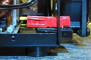
First pair of powerpole housings in place:
If you look closely, you can see how the half-circle indentation on the side of the powerpole housings is sitting on the metal edges of the hole.
Next, take one of the metal knockouts (you saved them, right?), and place it edgewise in the hole, up against the powerpole housings. This acts as a spacer to keep the powerpole housings from sliding back-and-forth in the hole, and to add a little clearance between the connector pairs to make it easier to plug in cables. Be sure to set the knockout far enough back that it won't interfere with connecting powerpole housings.
Using the sheet metal knockout as a spacer:
Finally, insert the second pair of powerpole housings. This picture shows the red housing offset slightly to make it easier to get the housings into the hole:
Inserting second pair of powerpole housings:
Once the two pairs of powerpole housings are in place I put a zip tie around them to lock everything down. Make sure you've got the powerpole housings fully snapped together and lined up. Later, I also added a little glue, but I don't have a good picture of that.
Here is a photo of the first set of powerpole housings installed in lower hole:
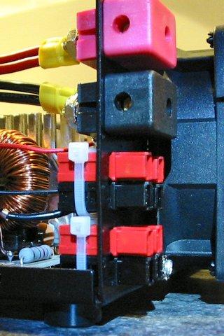
Now that you've got the lower set in, repeat the process to to install the upper
set. Here is a picture showing both sets of housings installed and tie-wrapped:
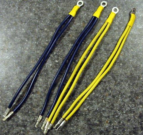
Next you need to prepare some wire jumpers to get power to the powerpoles. Since
I might be pulling as much as 15 or 20 amps through one of the powerpole connections,
I made sure to use 12 gauge wire. I made the jumpers about 6 inches long. They could
be a little shorter, but I've found it a little easier to install them when they are
about 6 inches. Make four jumpers - a ring connector at one end, connected to two
wires, with the powerpole contacts crimped and soldered to the ends:
At this point, you will want to remove the red and black wires from the back of the set screw connectors. This is also where you will end up connecting your new jumpers. Note that Astron puts some threadlock compound on the nuts on the back of the setscrew connectors, so they may require a little force to remove. Just be careful not to break or strip anything.
Starting with the bottom set of powerpoles, insert the pin ends of the jumpers. Again, pay attention to the order you do this, so you start with the furthest back powerpoles, so you don't get in your own way. Also, be careful not to get your red and black (or blue and yellow, as in the pictures) jumpers twisted around or through each other.
Comment from WA6ILQ:
Make sure the contacts are rightside up! The contacts will slide into, and
lock into the housings upside down! If you get a contact in wrong, you will
probably have to remove the housing to get the contact removal tool into
position to release the spring catch and get the contact out so you can
flip it over and reinsert it. Been there, done that....
And of course, make sure you are keeping your positives and negatives correct. You really don't want to cross wire anything.
Installing first set of jumpers:
Once you've installed all four jumpers, it is time to connect the black (or blue) wires to the back of the black setscrew connector. NOTE: Right now is a really good time to reattach that short black jumper you disconnected a few steps back. When you tighten the screw, make sure the ring connector on the circuit board end of short black wire is not touching anything, like the lead of that big resistor right next to it.
Now, bend the black (or blue) wires around so you can get the ring connectors onto the screw on the back of the black setscrew connector. All of the things you need to fit on this screw will pretty much take up all the room available, so you may have to work things around a little bit, or flip over a ring connector to get everything to fit. When everything is in place, it should be in this order: NUT - ASTRON SUPPLY LEAD - POWERPOLE JUMPERS - SHORT BLACK WIRE TO CIRCUIT BOARD - SETSCREW CONNECTOR.
This would be a good time to make sure you haven't accidentally cross wired a connector. You don't want to connect the negative to positive. Better to spend a minute checking a second time than say "Oops" later on.
Route the excess wire around so it isn't rubbing up against anything, particularly the aluminum heatsink. Make sure it doesn't interfere with the fan, or airflow towards the heatsink.
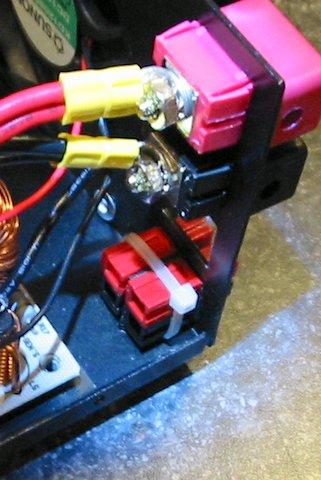
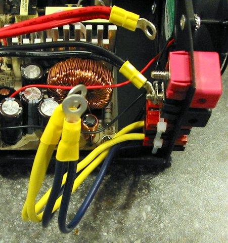
First set of jumpers installed and connected:
Once you've got the first set of jumpers connected, hook up the second set of jumpers. Again, double check that you haven't cross wired anything. The order on the back of the red setscrew connector should be: NUT - ASTRON SUPPLY LEAD - POWERPOLE JUMPERS - SETSCREW CONNECTOR.
Also, make sure that you don't have any of the ring connectors turned upwards, where they could get in the way of putting the power supply case back together.
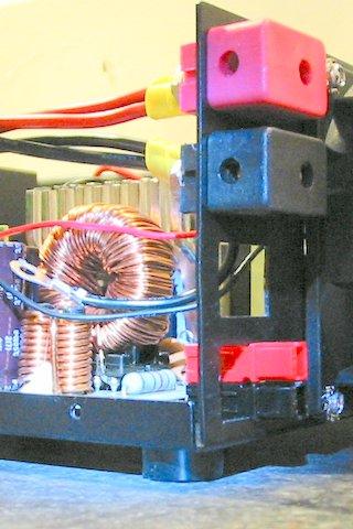
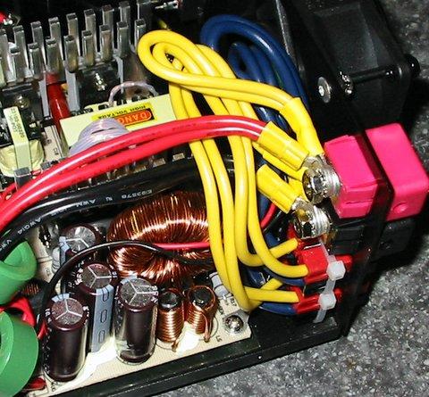
Here is what it looks like when it is all done. The jumper wires don't necessarily have to curve back the way they do in this picture. In one of the other conversions I've done, they ended up more to the left, over the capacitors.
Before you put the case back together, check that:
Here is what the finished product looks like:
Acknowledgements and Credits:
Repeater-builder would like to thank Robert for permission to clone his web page.
The original is on the Yolo Amateur Radio Society web page at
http://www.yars.org/kc6uds/AstronSS30PowerPole.html.
(Yolo is the name of a county in northern California).
Contact:
Robert Schulz KC6UDS can be contacted at (his callsign) //at// gmail //dot// com
(email addressed disguised to prevent spambots from picking it up)
Back to the top of the page
Up one level (Astron index)
Back to Home
This page originally posted on 08-Jan-2008
Photos and article is © Copyright 2008 and date of last update by Robert Schulz KC6UDS. All Rights Reserved, including that of paper and web publication elsewhere.
This web page, this web site, the information presented in and on its pages and in these modifications and conversions is © Copyrighted 1995 and (date of last update) by Kevin Custer W3KKC and multiple originating authors.