Back to Home
GE MASTR II 5C ICOM
By Robert W. Meister WA1MIK

|
GE index Back to Home |
Playing with the GE MASTR II 5C ICOM By Robert W. Meister WA1MIK |
|
Background:
Non-synthesized radios depend on quartz crystals to determine the transmitter and receiver frequencies. The crystal frequencies change with temperature; that's just how they are. If you can hold the temperature constant, the frequency will be constant. In the 1950s and 1960s crystals were installed in small heated plug-in modules that kept them around 70C. In the 1970s and 1980s the crystals were kept at ambient temperature and other temperature-sensitive components were added to try to compensate for the frequency changes inherent in the crystals. Motorola used several small compensating capacitors in their MICOR channel elements that would increase capacitance as the temperature rose, counteracting the increase in frequency that the crystal exhibited. GE used a varicap or varactor diode in their MASTR II crystal modules that changed capacitance according to a DC voltage fed to it. A small sensor module adjusted the DC voltage according to the ambient temperature. This article looks at the GE method of how crystal frequency is maintained.
Something peaked my interest a couple of months ago and I gave some thought to how Temperature Compensation (TC) works on the GE MASTR II ICOM (Integrated Circuit Oscillator Module). Kevin W3KKC was working on adding a crystal heater to an EC ICOM, and I wondered if some sort of external compensator could be easily built to perform the TC task.
There are already a few good articles about the ICOMs and their features. The 5C ICOM consists of a reasonably stable 5 Parts Per Million (PPM) crystal oscillator and a Temperature Compensation Module (TCM) that provides a correction voltage to the 5C ICOM as well as other modules plugged into the same receiver or transmitter strip that do not have a TCM in them. These are the EC (Externally Compensated) ICOMs that are basically 5C ICOMs without the TCM. They depend on another ICOM's TCM. There are also 2C (2 PPM) and 1C (1 PPM) ICOMs. Only the 5C ICOM provides a TC signal to be used by EC ICOMs; the 2C and 1C ICOMs also have a TCM but only compensate their own oscillators. A single 5C ICOM can supply a TC voltage for up to 15 EC ICOMs.
The Basic Oscillator:
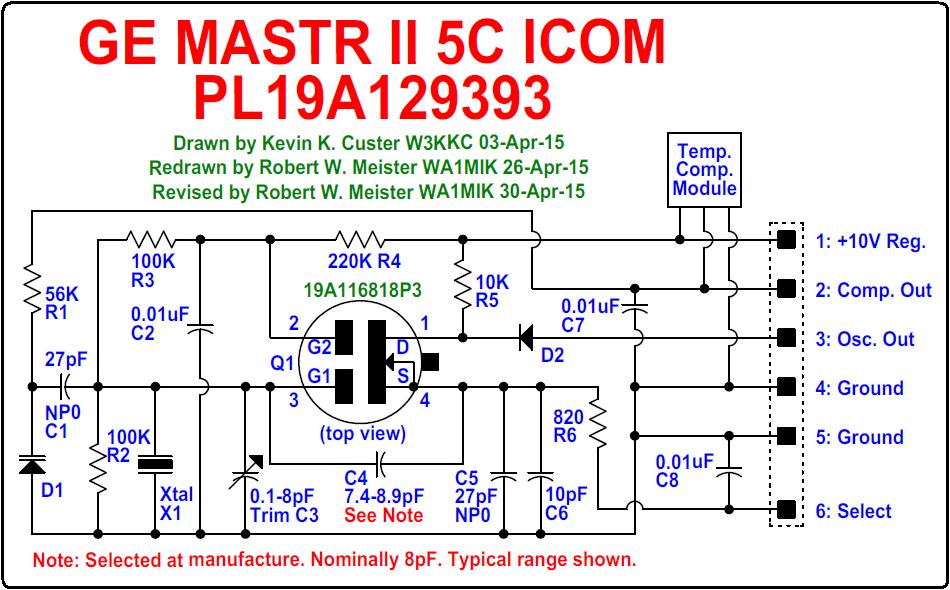
Refer to the schematic below. The 5C ICOM uses a dual-gate MOS-FET (Q1) as an oscillator. A piston-type trimmer capacitor (C3) is used to put the crystal (X1) on frequency. The output is rich in harmonics and depends on the first tuned circuit in the radio's multiplier stage to select the proper harmonic. A spectrum analyzer reports the amplitude (dBm) at the following harmonics and frequencies (MHz):
| Harm. | Freq. | Ampl. |
|---|---|---|
| 1 | 13.34 | +0.8 |
| 2 | 26.69 | -11.2 |
| 3 | 40.04 | -2.7 |
| 4 | 53.39 | -9.5 |
| 5 | 66.73 | -10.1 |
| 6 | 80.08 | -10.7 |
| 7 | 90.43 | -23.5 |
The ICOM that I used for testing was set up to receive 30.640 MHz. The crystal formula for the low-band VHF radio this ICOM came from is:
               Fcarrier + 9.4 MHz
    Fcrystal = ------------------
                       3
or

    Fcarrier = (Fcrystal * 3) - 9.4 MHz
If Fcarrier is 30.640 MHz, then the crystal frequency should be 13.346667 MHz. Here's the schematic of the 5C ICOM, which was hand-drawn by Kevin W3KKC and redrawn by the author:
Temperature Compensation Circuitry:
The varicap diode D1 at the left side of the schematic above provides a varying capacitance to alter the oscillator frequency. R1 supplies the diode with the TCM's control voltage. This voltage is also sent out on pin 2 of the ICOM connector to feed the EC ICOMs in the receiver or transmitter.
The basic ICOM accuracy is 2 PPM from 0C to 55C with no TCM. Between 0C and 50C, the TCM output voltage is 5VDC or one half of the 10V regulated voltage on pin 1 of the ICOM connector. As the temperature exceeds 50C, the TCM output voltage starts dropping to nearly 3VDC, increasing the capacitance of D1 and reducing the oscillator frequency to counteract the way the crystal naturally increases frequency. It reaches its limit at 75C. As the temperature goes below 0C, the TCM output voltage starts increasing to just over 6VDC, decreasing the capacitance of D1 and increasing the oscillator frequency to counteract the way the crystal naturally decreases frequency. It reaches its limit at -30C. The TC voltage is NOT linear over the temperature ranges.
Opening the ICOM:
The first thing I had to do was get the ICOM open. It seemed easy enough: pry the metal case away from the tabs in the plastic connector base and slide the guts out. Well, it wasn't quite that easy. I huffed and I puffed and I tugged at that base but the rest of the ICOM only moved about 1/8 inch and would go no further. I even tried pushing it out through the hole at the other end of the case. Nope, it just would not budge. In fact it felt as if a spring wanted to pull it back into the case.
Now I know another acronym for ICOM: "I Can't Open Mine!"
In desperation and because I wanted a quick answer, I called Kevin who told me the secret. There's a little slot on the side of the ICOM near the top. You have to stick the tip of a soldering iron in there and heat up a connection to free the guts from the case, while pulling the guts out. Even after that, I found I needed three hands, but I did manage to extract the guts from the case. I never figured out what was actually holding it in there. There's no evidence of any metal tang or solder inside the case. (Motorola MICOR channel elements are much easier to open and the parts are larger.)
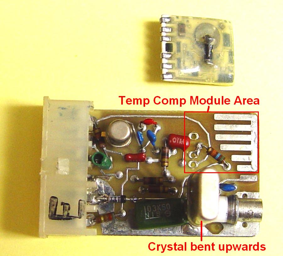
Here's a photo of the guts. The blob in the upper right is the TCM. The crystal is in the lower left and is mounted flat to save space.
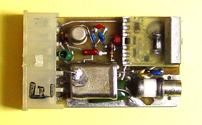
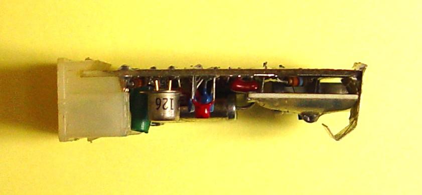
The 6-way plastic connector is at the left. Here's a side view showing the orientation of the various parts, the TCM, and the metal ground clip:
I completely unsoldered the metal ground clip that covers part of the TCM. Now you can see the entire TCM.
I unsoldered the TCM from the main board and folded the crystal upward. Here you can see what's beneath both.
I flipped both assemblies over and identified the signal pins on the TCM. I also soldered a short insulated jumper wire from the select line on pin 6 to the large ground pad for pins 4 and 5.
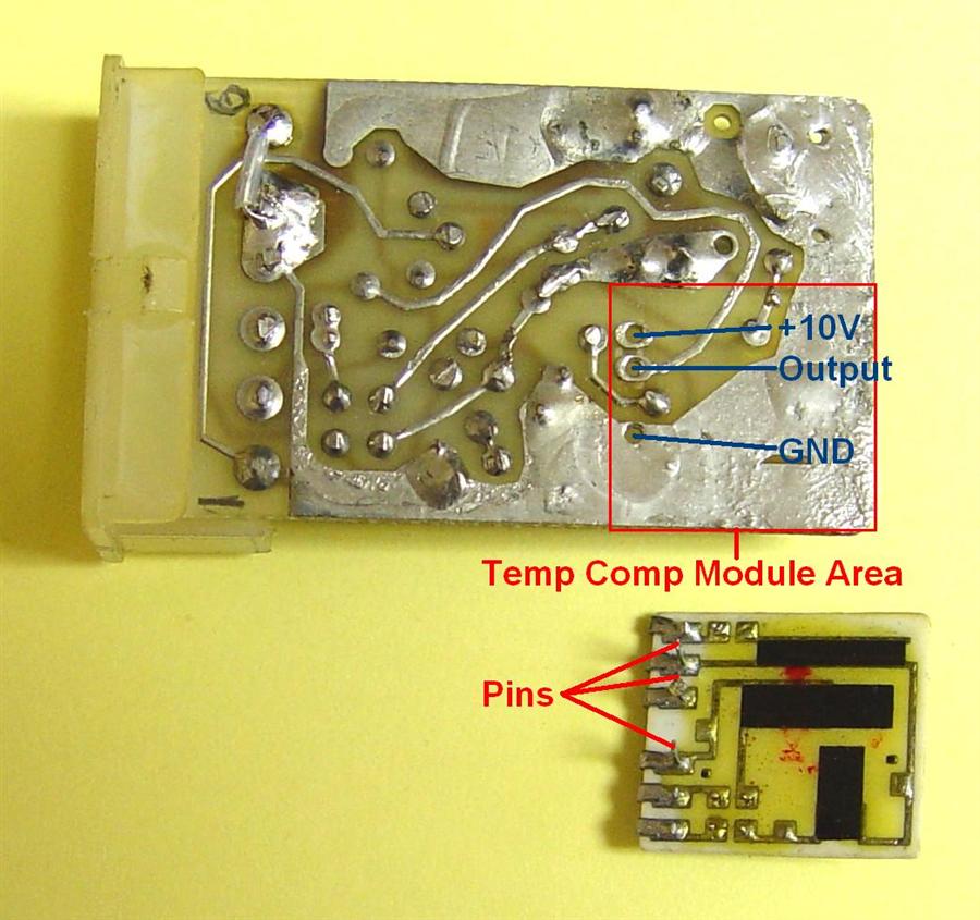
Even when viewed this way, there are still foil traces that can't be seen, and one runs under the nylon connector body.
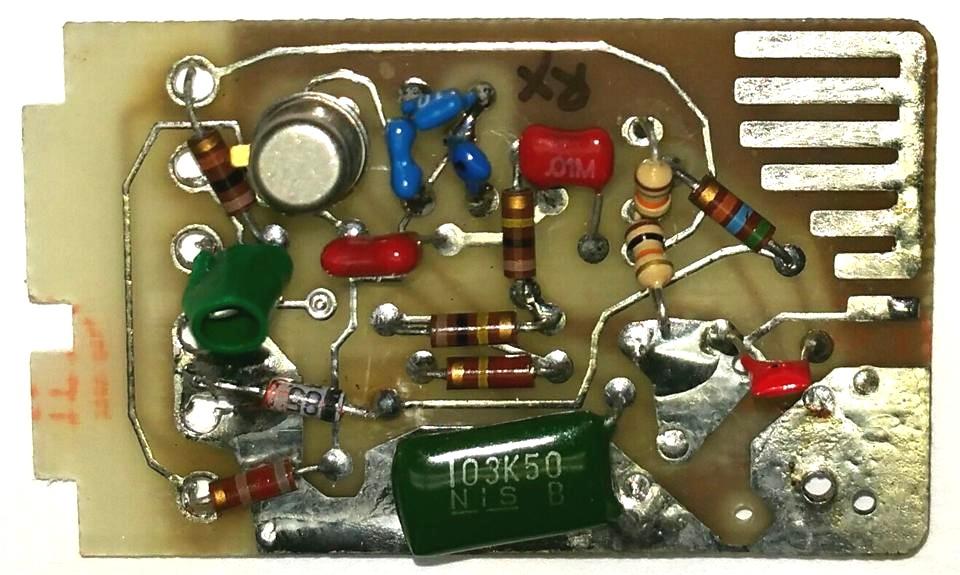
Kevin W3KKC removed the connector from an EC ICOM and supplied the photo below. He also added a pair of 10k resistors in place of the TCM, but you can see how the connector covered one trace.
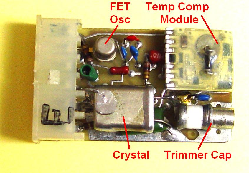
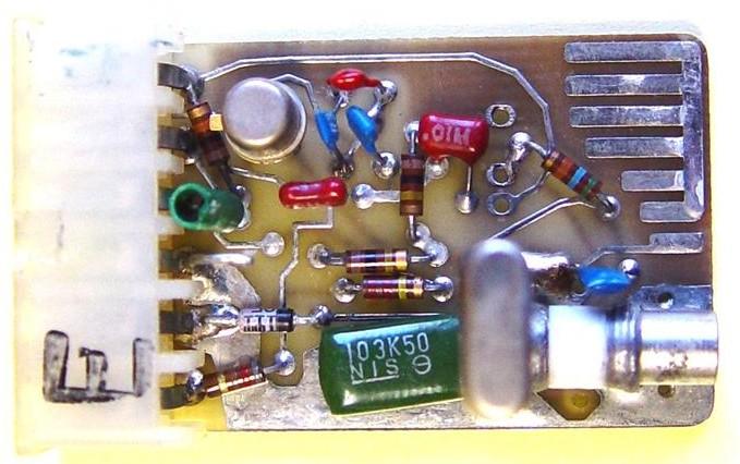
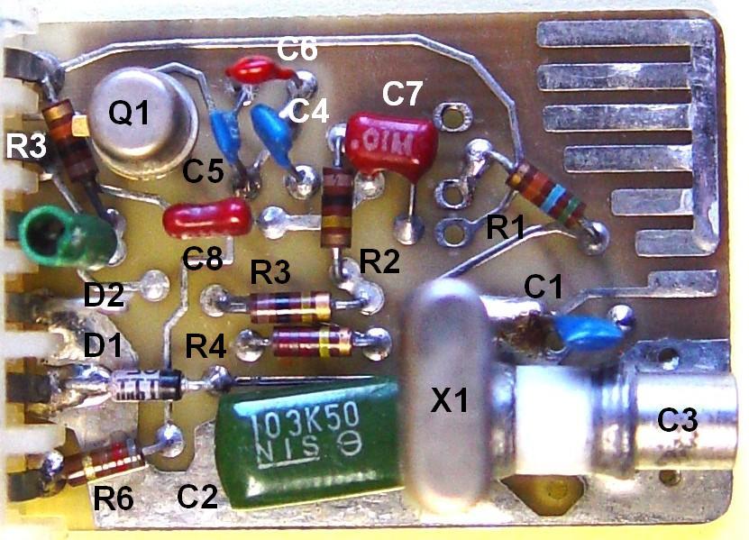
I had no reason to dissect the ICOM further. After assigning part identification numbers in the schematic, I annotated a photo of the ICOM with these same ID numbers.
Testing the Temperature Compensation Circuitry:
I connected pin 1 to a variable DC power supply. I connected the output pin 3 to a frequency counter and a 560-ohm load resistor going to +10V. I connected ground to pin 5.
Due to the harmonic content of the ICOM, my counter registered the frequency of the second harmonic. So in the table below, 26.694199 MHz is twice the actual crystal frequency of 13.347099 MHz. The ICOM frequency should be 13.346667 MHz so it needs to be adjusted but I'm not worrying about that right now. Here's a scope trace of the ICOM output. Each of the highest peaks is about 74 nS apart, yielding 13.3 MHz, but as you can see, there are two other peaks between each tall peak, which is what produces energy at 26.6 and 39.9 MHz.
I measured the room-temperature frequency of the ICOM and recorded that. I then used some freeze spray and coated the TCM with a layer of snow. The TC voltage started rising and the output frequency was recorded. Finally I used a hair dryer to heat the entire ICOM. It took a long time but eventually the TC voltage started falling. I took another frequency reading as soon as I removed the heat but the TC voltage was already starting to recover. Here are the voltages and frequencies I got with this ICOM. Remember that the counter is picking up the second harmonic of the crystal.
| Temperature | TC Voltage | Frequency |
|---|---|---|
| Cold (-30C) | 6.00 | 26.694285 |
| Normal (25C) | 5.00 | 26.694199 |
| Hot (75C) | 4.00 | 26.694438 |
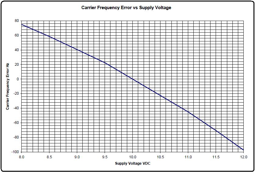
NOTE: The frequency error in the graphs below is the error (in Hz) that would be experienced at the actual carrier frequency, which is supposed to be 30.64 MHz. This is three times the crystal frequency minus 9.4 MHz. The 5C ICOM has a 5 PPM specification, so its output can vary up to 65 Hz and still be in spec. The carrier frequency can vary up to 195 Hz and still be in spec.
Next I tried varying the power supply voltage from 8 to 12 volts while measuring the TC voltage on pin 2. The TC voltage remained at 50% of the ICOM's input voltage and the output frequency varied significantly. Fortunately, the 10V supply inside the GE radio is very well regulated, but I wanted to see what effect it would have on the ICOM's output frequency. The graph below shows how it reacted.
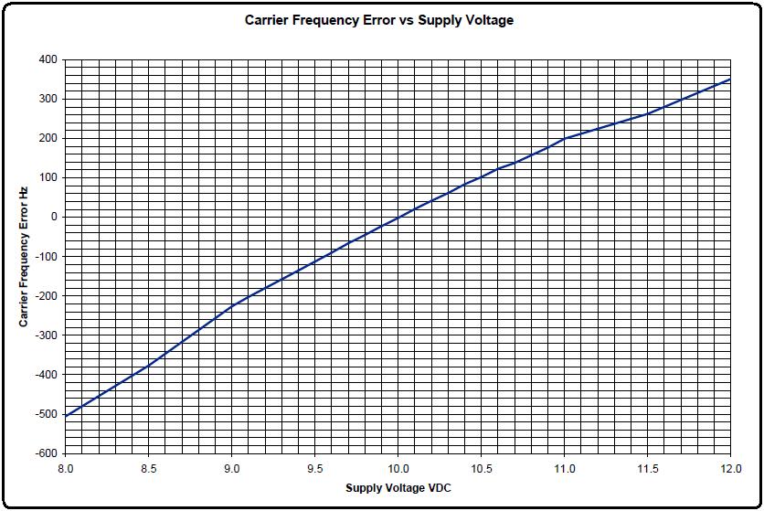
You can see that the frequency increases as the ICOM supply voltage increases, but the TC voltage is also changing, since at room temperature it is approximately 50% of the supply voltage. Most 10V supplies in GE MASTR II radios are very well regulated, and this is the reason they have to be, because the ICOM, particularly the TCM and varicap diode, are very sensitive to voltage changes.
I unsoldered the TCM and connected a variable power supply to pin 2, the ICOM's TC signal. I then set the supply voltage to 10.00VDC and varied just the TC voltage. The graph below shows how the frequency changed.
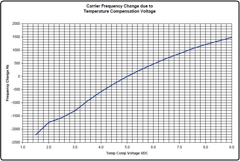
As you can see, this graph is similar to the first one in that the frequency increases as the TC voltage increases. Normally the crystal frequency would increase as the temperature rises, and the TCM reduces its output voltage to compensate for the change in temperature, thus holding the frequency within spec.
Finally, to determine if the oscillator itself was susceptible to voltage changes, I set the TC voltage to 5.00 and varied the main supply voltage. The graph below shows how the frequency changed.
Now we can see that there is a very small change in frequency as the ICOM voltage is changed, and it is opposite to what the TC voltage change invokes. So the majority of the frequency change that occurs when the ICOM supply voltage varies is due to the TC voltage changing as well.
Reference Material:
Several GE LBIs had information about how the ICOMs were connected as well as how they worked and how the TCM was designed to react to temperature changes. These can all be obtained from the GE LBI Library on this web site.
lbi-4560b.pdf: MASTR II VHF transmitter
maintenance manual
lbi-4561c.pdf: MASTR II VHF receiver maintenance
manual
lbi-30043k.pdf: MASTR Executive II maintenance
manual, crystal modules, etc.
Acknowledgements and Credits:
Thanks go to Kevin W3KKC for drawing the schematic of the 5C ICOM and doing some dissection of his EC ICOM.
Various GE LBIs were viewed to obtain information about ICOMs and temperature compensation.
Contact Information:
The author can be contacted at: his-callsign [ at ] comcast [ dot ] net.
Back to the top of the page
Up one level (GE index)
Back to Home
This article created Friday 01-May-2015.
Photographs, article text, and hand-coded HTML © Copyright 2015 by Robert W. Meister WA1MIK. All photographs were taken by the author unless otherwise indicated.
This web page, this web site, the information presented in and on its pages and in these modifications and conversions is © Copyrighted 1995 and (date of last update) by Kevin Custer W3KKC and multiple originating authors. All Rights Reserved, including that of paper and web publication elsewhere.