Back to Home
50 or 100 Watt Power Amplifier
as a Linear Amplifier
By Chuck Schreiber K9VPE

|
GE index Back to Home |
Using a GE MASTR II 42-50 MHz 50 or 100 Watt Power Amplifier as a Linear Amplifier By Chuck Schreiber K9VPE |
|
My PA is an earlier one, circa 1979. You can find LBI-4898 in the LBI Library section of this web site. There are several revisions and file sizes available. Most power amps were basically the same through out the life of the MASTR II. The transistors are 19A134104P1.
The beauty of setting up the PA in this way is there are no parts to change and no tuning is needed. The 42 to 50 MHz PA will easily cover 40 to 53 MHz, thus the popularity for use as a six-meter repeater. I have seen many GE MASTR ll Low Band stations and mobiles make 150 watts output.
Single sideband requires that the whole power train be linear. Using a Class C amplifier (such as an FM PA) will result in unintelligible transmitted signal. In order to make it operate linear you must bias the transistors into their linear region. In my case this required 0.5 volts dc.
Amplifier Modification:
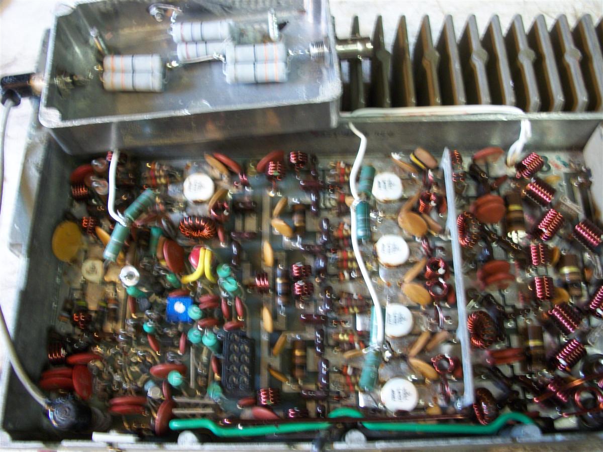
Each transistor (Q204, 205. 206, 207, 208, and 209) has a green RF choke between its base and ground (L208, L209, L225, L226, L227, and L228). There are also a number of resistors soldered between the base and ground. No need to disturb these.
Carefully heat the ground end of the chokes, lift them off the board, and stand them straight up. Now tie all the ungrounded ends of the chokes together using 18 or 20 gauge insulated hookup wire. Find or make a hole in the heat sink and route the wire underneath the PA. Bypass each connection at the chokes to ground with a 0.01 or 0.05 uF disc capacitor rated at 250 V or more. The photo below shows the modified PA. The white wires were added for bias.
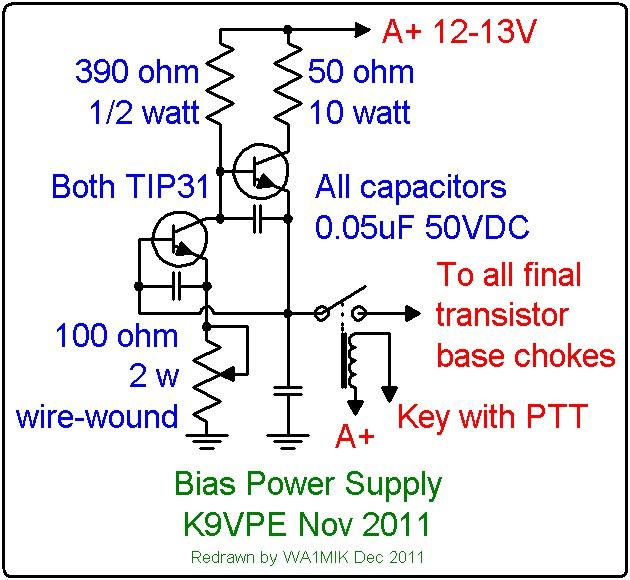
Bias Regulator:
The bias regulator uses two TIP31 or better transistors. The idea is to supply a steady bias current under various drive conditions. I insulated them and mounted them to the heat sink.
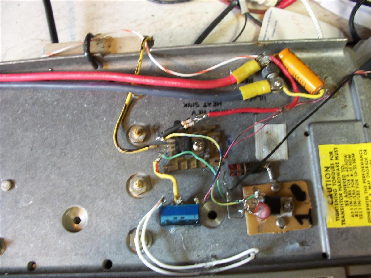
Build it as shown in the schematic below or design your own. I also incorporated a small relay and used the normally open contacts to remove the bias current when not transmitting. The aforementioned resistors will hold the bases down to prevent run-away. Key the relay with the PTT along with the on-board antenna relay.
Testing:
Now let's set it up and see if it smokes! The GE PA only requires 1 to 1-1/2 watts of drive to produce 100 watts class C. My biggest challenge was to pad my homebrew exciter down from 18 watts. There are several ways to do this but remember to keep the input around 50 ohms. In my case I built a 10 DB pad. My first error was hitting it with about 6-7 watts. CR201 was blown in the power control circuit. Now that you have your drive solved (don't apply RF yet) set the power control pot R261 to about mid-point, apply A+ to the amplifier and regulator. (Don't forget to energize the relay.) Put the voltmeter across the bias circuit and set it for 0.5 volts DC. That's all the setup I did. Put some CW drive on it and adjust the power control for whatever power out you are comfortable with. I settled for 90 watts and noted the input current of 13 amps; I switched over to USB and the voice peaks were running 13 amps; 168 watts in; probably 200 watts PEP out.
Things I know that can cause problems: High Antenna VSWR. (It can couple back into the input and make it run.) Power Supply regulation. It has to maintain A+ on voice peaks, otherwise it will "Flat Top". It looks pretty clean on a 50 MHz scope. Don't over drive it. I get good Q5 signal reports and so far no splatter complaints. I am powering the amp with an Astron RS20 and the peak current is 12-13 amps at 13.2 volts. I don't know if the MASTR II base power supply would work, as it has no regulation.
Contact Information:
The author can be contacted at: chucklin [ at ] att [ dot ] net.
Back to the top of the page
Up one level (GE index)
Back to Home
This page originally posted on Friday 02-Dec-2011.
Article text, drawings, and photographs © Copyright 2011 by Chuck Schreiber K9VPE.
Artistic layout and conversion to repeater-builder format © Copyright 2011 by Robert
Meister WA1MIK.
This web page, this web site, the information presented in and on its pages and in these modifications and conversions is © Copyrighted 1995 and (date of last update) by Kevin Custer W3KKC and multiple originating authors. All Rights Reserved, including that of paper and web publication elsewhere.