General Information on
the MASTR II Mobile
Some things to consider before you start your conversion, and info
to help get it going.
** Use this information only as reference, not as explicit conversion
procedure as that is covered in the Step-By-Step procedure. **
Assumptions:
Assumptions I have made are that you have a MASTR II which properly
operates, you have your crystals and they are mounted in the ICOMs.
Bomar Crystal Manufacturing
is a good source for MASTR II crystals.
Powering Concerns:
Since the MASTR II was designed to be used in either a positive or
negative ground vehicle, the A- is NOT connected to the chassis ground,
but it is desired to strap them together when building a repeater.
There are several power leads for the MASTR II. There are the
large RED lead that powers up the PA (TX A+), then there is the A+ (16
Ga yellow) and IGN SWITCH (red). All of those need +13.8 Volts DC.
Then there are the grounds: The large BLACK wire (TX A-)
and the A- (16 ga black), these can all be tied together.
If you don't have voltage connected to all of the points necessary (common
when you don't use a control head and cable) the radio won't operate correctly
or at all.
If you are either using a control cable or not, you need to insure all of the
voltages and grounds are being supplied as connecting voltage to the two large
terminals only supplies power to the Transmitter PA, again, as the radio was
designed to operate either positive or negative ground and the chassis is not
connected to A- (power ground), but it needs to be. Also, A+ needs supplied
to the IGN lead and A+ lead as this supplies voltage to the rest of the radios
circuitry.
Install a 3 to 5 amp fuse in a holder from the large red wire to both the IGN
and A+. Then install a wire from the large black lead to both A- pins.
Refer here for the pin assignments to get the radio powered up.
Volume/Squelch Controls:
There are several ways to do this.
1) You can use the control head and cable as it was intended from the factory.
2) You can remove the pots and install them inside the radio by drilling
the plastic wall between the compartments and wiring them directly.
3) Use the NHRC
Vol/Sq pots. This is the easy way out, and cheap too...
Heating and cooling
These issues are always a problem, depending on the power output ability of
your MASTR II will dictate how much cooling is required. I have a 110-watt MASTR
II mobile as a 2 meter repeater, I'm sending 54 watts in to the duplexer.
I added a fan on the top cover of the radio over the PA deck and an air inlet
slot to the left of the PA deck on the top. I also added a few fans to blow cool
air over the heat sink fins.
I also have a 75 watt MASTR II as one of our 70-cm repeaters which is putting
about 25 watts in to the antenna, this installation required no additional cooling.
Don't push your MASTR II's PA deck to the limit. A MASTR II's PA system will
deliver more power than the RF parts can handle, too much current will pass and
you will lose the PA. Also, the removal of heat from the RF parts mounted in the
heat sink are an issue.
We all want to exhibit as much power as we can, and I'm no different than
you. You can push the PA deck to maximum power (110 watt VHF deck will do
140 to 160 watts) but the heat sink can not take the heat away fast enough.
Let's look at GE's continuous duty rating for each of the three PA decks:
Series 5, 35 watts - Series 6, 45 watts
- Series 7, 55 watts
MASTR II PA decks should not be adjusted to less than 40% of their rating.
This is because of noise and spurious emission. My suggestion is to add
a cooling system to your PA deck as described above and keep your power output
within reason. Remember, 6 dB equals one S unit, so a few extra watts
will mean nothing.
Desense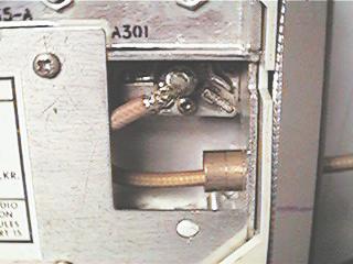
Desense is an issue that is sometimes difficult to deal with because of
the unknowns. Any desense at all will degrade the receivers sensitivity. The
more critical 2 meter repeater (600 kHz split) has 10 dB of quieting with
a 0.32 uVolt signal while the transmitter is wide open (160 watts). What I
did was to add a BNC connector to the side of the radio by the receiver's
antenna input jack. I then added a piece of copper pipe from the side panel
of the radio into the receiver compartment. With out this shielded tunnel,
I could not get the duplex sensitivity that I stated above. The coax
connecting the original antenna port (which will become the transmitter port
when building a repeater) is not double shielded. It should be replaced
with RG-142, RG-400 or similar coax.
Of course, always use double shielded cable in you installation. Use
RG-142 or RG-400 for the interconnections from the PA and receiver to the front
panel of the chassis. Use a "hood" to insure the connections are 100%
shielded at connectors.
I use RG-214 for the transmitter and receiver signal path from the radio
set to the duplexer. If you are going to use a pre-amp, wire it in as
close to the duplexer as possible. This will eliminate any amplification
of noise that may have found it's way in to the coax.
ICOMs
ICOM's are Integrated Circuit Oscillator
Modules,
house the crystal used in the MASTR II radio. The come in three versions,
2C, 5C and a EC. EC ICOMs are designed to work with 5C's. You
should have one 5C installed which can temperature compensate many EC ICOMs.
The 2C ICOM can not temperature compensate an EC.
Here is a comprehensive
description of the GE MASTR II ICOMs from Hall Electronics.
MASTR II crystal frequency calculations
The IF frequency for both the UHF and VHF M2 is 11.2 MHz, CF equals
the crystal frequency.
 UHF Receiver - ((cf * 9) * 3) +
IF = Receive frequency.
UHF Receiver - ((cf * 9) * 3) +
IF = Receive frequency.
UHF Transmitter - (cf * 12) = Transmit
frequency (PA has a tripler.)
VHF Receiver - (cf * 9) + IF =
Receive frequency.
VHF Transmitter (cf * 12 ) = Transmit
frequency.
GE Channel Guard
CTCSS, Channel Guard, or PL... (what ever you want to call it)
The GE Channel Guard boards will not work as a full duplex encoder/decoder.
I use the Communications Specialists TS-32 or TS-64 encoder - decoder.
If the MASTR II you have had/has a GE Channel Guard (CTCSS, PL) board
installed, or you can not get the transmitter to fire up (the transmit
relay does not click) your radio may have been equipped with GE's Channel
Guard board. Removing the Channel Guard board has likely broken the
PTT path. You can check this simply by plugging the CG board back
in place to see if the PTT path is restored.
Systems Boards
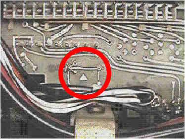
There are at least two different types of Systems Boards. Look
at the Systems board, to the left you will see the exciter connector, just
below that you will see a 9 pin connector referred to as P908, just below
this connector and below the right 3 pins of the this 9 pin connector you
may see the image pictured with the Delta symbol. If you see the
Delta (triangle), you will see a solder pad to either side of the symbol.
To get your transmitter to work with out GE's Channel Guard board, you'll
need to have a jumper installed on these solder pads. If your radio
has a Specialty Systems Board, it won't have the Delta symbol and thus
pins 6 and 8 on P908 either need jumped or you can pick-up the PTT connection
at pin 8 on P908. Remember P908 is the 9 pin connector on the Systems
Board that mates with the CG board, (the one in front of the exciter board).
CAS and RUS
CAS stands for Carrier Activity Sensor. It will go to around 10 volts
(active high) when the receiver is un-squelched, but this pin produces a choppy
representation of logic when a user is in flutter. RUS should be used for
COR to the controller. If you are using the factory Channel Guard board for tone
decode in a MASTR II, you cannot use CAS, you need to use RUS anyway. If
in tone decode mode using the factory CG board, only the audio is muted. The CAS
(or COS as some refer to it as) will still go high without the tone. RUS
line will go high only if the tone is decoded. RUS line is not on the front
connector. It is found on the audio/squelch board pins next to the CAS. RUS
is the RX squelch logic signal and stands for Receiver Unsquelched Sensor and is
available at J904-8.