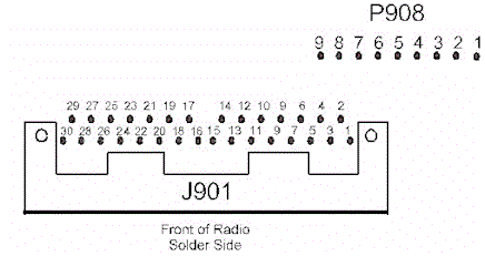
Where to get the signals from a MASTR II

Where to get the signals from a MASTR II

Pin 39 is the large terminal where the large RED lead connects.
This is the radios main positive voltage connection referred to as
A+.
Pin 40 is the large terminal where the large BLACK lead connects.
This is the radios main ground or negative voltage connection referred
to as A-.
Pin 30 is another A- that needs tied directly to the TX A- (large black lead, pin 40)
Pin 21 is Control A-, this also needs tied directly to the TX
A- lead.
This is a good place to tap your signal ground for audio and logic.
Pin 29 is A+, this needs tied to the large TX A+ lead through a 3 to 5 amp fuse.
Pin 24 is the Ignition Switch Sense, this also needs tied to the large TX A+ lead through a 3 to 5 amp fuse.
Pin 4 is the transmitter audio input connection point (Mic Hi), Pin 2 is the audio input ground (Mic low). Pin 4 has a +10V bias applied which powered the microphone preamp. Depending on your repeater controller, you may need to insert a DC blocking capacitor. If you are going to use a mic on the control head, you should insert a resistor in series with the controller's audio output to prevent the controller from loading down the microphone's output, a 5K resistor should do it.
Pin 20 is the un-squelched (and is not de-emphasized) audio output
(VOL/SQ HI) and offers around 1 V peak to peak RMS. You may have
to add a decoupling CAP to this line depending on your repeater controller's
audio input circuit. You may also have to add a resistor in series
to reduce the loading on the discriminator. My advise is to add a
RC circuit, like the one shown here, to de-emphasize the audio if your
repeater controller does not  have
it built in, this will eliminate the tinny sound. Wire one side of
the 15K resistor to pin 20, and the other side to one side of a .22µF
capacitor. Ground the other leg of the capacitor. Take the receiver audio
from the capacitor-resistor junction. These values can be changed
to suit your taste, some choose a 6.8 K resistor and the .22 µF
capacitor.
Pin 18 is the VOL/SQ LO or audio return for the pots.
Pin 19 is the Volume Control arm. Optionally you can tap audio out from here. The down fall of this source is that the audio level tracks with the volume control.
Pin 17 is the Squelch Control arm.
Pin 25 is the PTT line, take this line to ground to force the transmitter to on. You will need a circuit which can sink 75 ma of current.
Pin 16 is the CAS (carrier activity sensor). It will go to around 10 volts (active high) when the receiver is un-squelched, but this pin produces a choppy representation of logic when a user is in flutter. RUS can also be used for COR to the controller but this lead is not brought out to the control head connector pins. See RUS below.
Pin 28 is the speaker positive connection.
Pin 27 is the speaker negative connection.
The speaker connections must either be tied to a local speaker or terminated
in a load resistor.
RUS is the RX squelch logic signal for the MASTR II is available at J904-8 (Rx Unsquelched Sensor). There is another signal called "carrier activity sensor" available at J901-16, but I've found that using this signal results in increased chopping of weak signals. If using a DE-9 on the front of the radio to bring the I/O out, you can simply connect J904-8 to it. If using J901 with a mobile cable assembly for the I/O, you need to "reassign" one of the unused pins (I.E. "F4" on pin 11).
PL? Want to add PL encode and/or decode? P908 is the place to do it. Pin 1 is the same as Pin 20 and a ideal place to feed your PL decoder's input. Pin 4 offers 10 VDC+ and Pin 9 is A-, nice place to take power for your encoder/decoder. Pin 7 is the PL injection point, you can set the PL deviation level by a pot on the exciter board.
A DE-9 female can be mounted to the front left side of the radio in a small open space to bring out all of the signals in the radio.
Don't forget to place a PTT disable switch at the control point to allow
easy disabling of the transmitter for desense testing. This is a
must.
This site, its contents, and look & feel are Copyrighted©
2001 Kevin Custer W3KKC
All Rights Reserved.