Common System Board
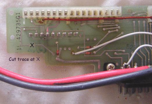
Pictured above is the solder side of the common system board which is
located at the front of the radio.
P901 is the control/power cable connector.
Modifying
the MASTR II System Board
for
full duplex operation.
By Kevin Custer W3KKC
Concept: Modification of the "System Board" to allow a GE MASTR II Mobile radio to operate full duplex. There are at least two different types of System Boards and information is provided in this article for both the Common and Special System Board.
It is necessary to activate the receiver circuits continuously by applying power to the "IGN" and "A+" leads. In the past, many builders have chosen to power these circuits directly with jumpers on the System Board. I feel a better method of supplying power to these circuits is through fuses located in holders. Since there are two methods of supplying the "IGN" lead with power, you can choose the option that best suits you. This option is explained in the text below.
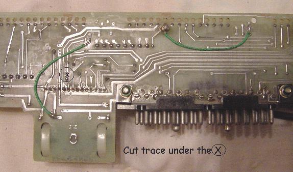
Common System Board
Pictured above is the solder side of the common system board which is
located at the front of the radio.
P901 is the control/power cable connector.
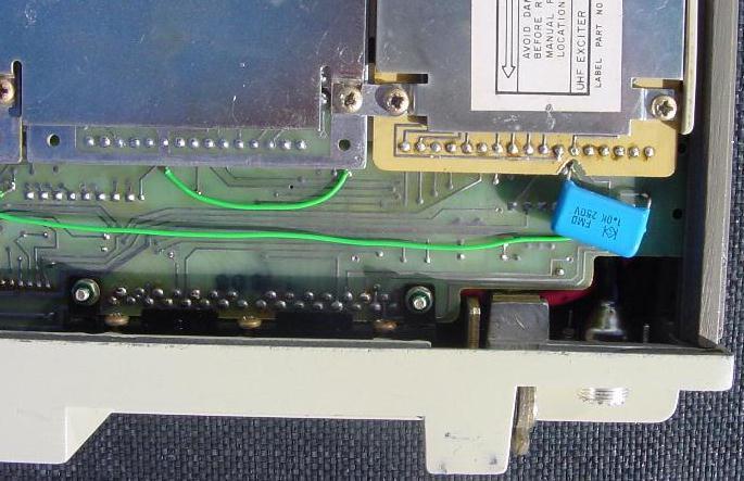
Pictured above is the solder side of the special system board which
is located at the front of the radio.
P901 is the control/power cable connector.
Option: There are two methods of supplying power to the receiver circuits continuously, you can jumper H89-H90 as in the common System Board outline, or you can supply A+ to these circuits via a fuse (preferred method) as indicated below in Step 1. Steps 2 - 4 need to be done no matter which method of powering the IGN is used.
Power connections:
Connections must be from the large power leads to the System Board
in order to supply power to the radio circuits. The control head
and cable, which we are not using, originally supplied this power.
I run wires, which are a few inches long, for these connections, on the
back side of the control head connector J901. Inline fuse holders
mounted in a convenient place make installing and replacing the fuse for
the IGN and A+ power paths easy. I have found the best place to connect
these leads is to the back of the control head connector as the points
are plainly marked with the pin numbers. You may need to remove heat
shrink from the large power connections where they solder to the back of
the control head connector to gain access to them.
Additional Note: In most cases selecting the F1 channel position as above will enable both the receiver and exciter F1 position. Sometimes the F1 channel select line is severed between the exciter and receiver. I check this line by doing a continuity check between P902 pin 8 and P903 pin 1 on the System Board. If these two points read shorted, the procedure outlined above will enable both the receiver and exciter F1 positions. If the two points don't read continuity, either fix the severed trace or tie both P902 pin 8 and P903 pin 1 to A-.
This site, its contents, and look & feel are Copyrighted©
2001 Kevin Custer W3KKC
All Rights Reserved.