Back to Home
Radios in Repeater Service
By Robert W. Meister WA1MIK

|
GE index Back to Home |
Using GE MLS-I Mobile Radios in Repeater Service By Robert W. Meister WA1MIK |
|
I recently was asked how to keep an MLS-I radio permanently turned on. There's info about how to do this to an MLS-II but I hadn't looked into it on the MLS-I yet. It turns out to be quite simple. After receiving some inspiration and other information on repeater connections from Len Kreyer N9QIP, I decided to write this article. It's similar to the MLS-II but there are some differences.
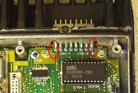
My only MLS-I radio is a two-channel VHF unit. One channel is programmed for carrier squelch on 162.400 MHz (one of the weather channels) and the other is in the 157 MHz range with 107.2 Hz Channel Guard. Fortunately the only available documentation (LBIs) on this site for an MLS-1 radio is for the VHF-HI model that I have. The RF board on other bands will be similar; the system control board and microphone connector are identical. All of the interface signals can be acquired on the top (Synthesizer and System Control) boards. Many of the signals can be acquired on the solder side of the SysCon2 plug-in daughter board. Unless otherwise specified, all photos and signals are on this plug-in board. See the MLS-I Overview article to familiarize yourself with the location of this board.
Program and align your radio and verify proper operation before attaching any wires to it. You can bring the necessary wires out the back next to the microphone connector or you can drill a small hole through the heat sink and snake a cable through that.
Click on any photo to see a larger image.
Required Signals:
To interface mobile radios to most repeater controllers, you need several signals:
The following paragraphs show where I found these signals and gives specific AC and DC voltages where applicable.
Transmit Audio Input:
The simplest and easiest place to get this is on the rear 8-pin Molex microphone connector at pin #4 (MIC HI). There is +9.6 VDC present here to power the preamp built into most GE microphones, so you will need to use a coupling capacitor of 10 uF at 16 V (or larger) between this point and your repeater controller. The input impedance is around 680 ohms. The audio will be pre-emphasized. You will need approximately 70 mV per 1 kHz of deviation at 400 Hz, depending on how you have set the deviation control.
Note that pin #8 is closest to the edge of the chassis. The mating Molex connector can be installed either way and even offset by one pin left or right. Make sure it's well labeled so it can't be installed incorrectly. Pin #8 has unfused switched +13.8 VDC on it and anything connected to that pin will have nearly unlimited current available to it when the radio is turned on. Read this article about a solution to this issue.
If your external repeater controller has limiters, filters, and a pre-emphasis circuit, you can feed flat audio into the radio by attaching it to the arm of the MOD ADJ pot RV201 on the Synthesizer board, under the cast metal shield. This may affect the radio's ability to properly generate Channel Guard signals, but most people who go this route also let their external repeater controller handle Channel Guard signals as well.
PTT Input:
This is also one of the easy ones to get on the rear 8-pin Molex microphone connector at pin #2 (PTT/RXD). This pin sits at +5 VDC and you bring it to ground to cause the radio to transmit. This pin will require about 0.5 mA of current, which can be supplied by a transistor, IC, or relay contact.
Receive Audio Output:
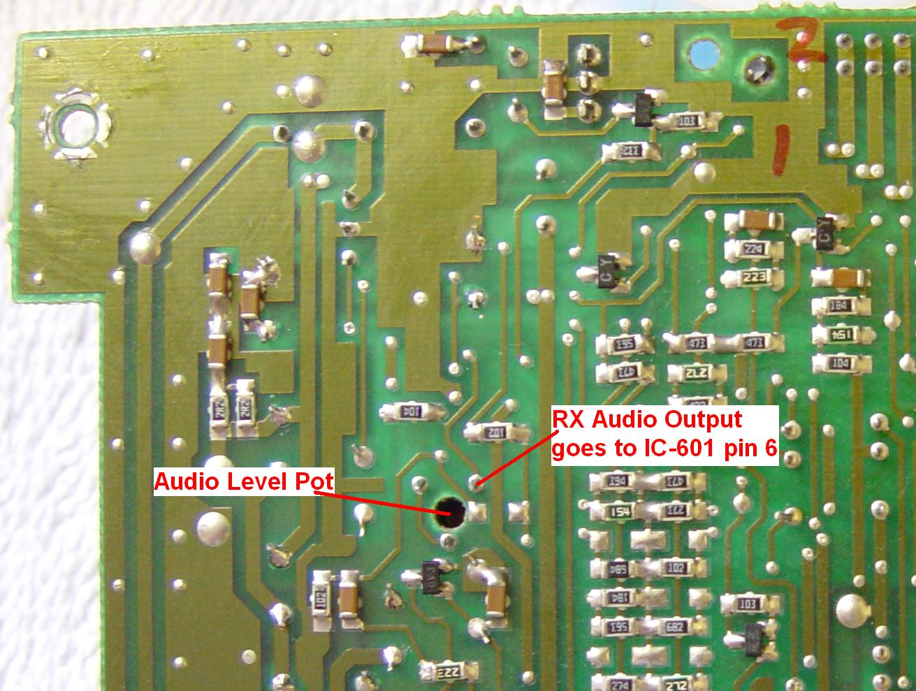
You can pick up detected audio on the SysCon2 connector pin #24. It has unsquelched flat (not de-emphasized) receive audio. There is 7.5 VDC present here, so you will need to use a coupling capacitor of 10 uF at 16 V (or larger) between this point and your repeater controller. The level is approximately 117 mV per 1 kHz of deviation. This signal feeds the volume control circuitry. You can also get it at IC601 pin #1 on the SysCon2 board.
A similar signal but at a level governed by RV601 (Audio Output Level Adjust) on the SysCon2 board, is also available. It is flat (not de-emphasized), has had Channel Guard signals filtered out, and IS squelched or muted. It is available on IC601 pin #8 on the SysCon2 board or the single terminal on RV601, indicated in the photo below. The level at this point will depend on how RV601 has been adjusted. On my radio, it was 108 mV per 1 kHz of deviation riding on 4.6 VDC.
Most repeater controllers can deal with flat audio and they have a de-emphasis circuit built in. They probably will work better with squelched or muted audio, but some will use the COR signal to mute the audio path internally. Check the controller's documentation.
Unfortunately the MLS-I radio's receive audio doesn't get de-emphasized until after the volume control, when it hits the loudspeaker's audio amplifier. While you can get it there, its level will be affected by the front panel volume control, which is not at all desirable for repeater use.
COR Output:
A good point is on the SysCon2 connector pin #20 (called Rx Mute 1). This has 5 V when no signal is present and 0 V when a signal with the correct Channel Guard is present on the carrier, or if you press the front panel MONITOR button to unsquelch the radio. If Channel Guard is not programmed, any received carrier will activate this signal.
Another place is pin #11 (called Rx Mute) on the SysCon2 connector. This has 4.3 V when no signal is present and 0.1 V when a signal with the correct Channel Guard is present on the carrier, or if you press the front panel MONITOR button to unsquelch the radio. If Channel Guard is not programmed, any received carrier will activate this signal.
You should use some sort of buffer on these pins. Don't connect either one directly to your repeater controller unless you know for sure that it won't load anything down.
Note that these signals will be activated any time the audio amplifier has to be turned on. This means if you press ANY front panel button that would cause the radio to emit a beep, these signals will be pulled to ground.
Ground:
Ground can be obtained from the black incoming power wire screw terminal, the microphone connector pin #5, or the SysCon2 connector pins 28-32.
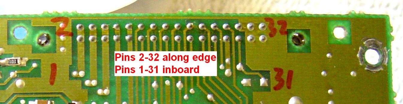
SysCon2 Connector Pinouts:
There are plenty of signals you can access on the SysCon2 connector, documented below. A photo of the solder-side of this connector can be seen in the next paragraph.
| Pin | Signal Name | Function | DC Voltages |
|---|---|---|---|
| 1 | A+ | Incoming Power | 13.6 |
| 2 | A+ | Incoming Power | 13.6 |
| 3 | SW A+ | Switched Power 13V | 13.6, 0.0 when off |
| 4 | SW A+ | Switched Power 13V | 13.6, 0.0 when off |
| 5 | Int Sp Hi | Internal Speaker High | 0.0 |
| 6 | Ext Sp Hi | External Speaker High | 0.0 |
| 7 | 5V | Switched Power 5V | 5.0, 0.0 when off |
| 8 | 5V | Switched Power 5V | 5.0, 0.0 when off |
| 9 | 9V | Switched Power 9V | 9.2, 0.0 when off |
| 10 | 9V | Switched Power 9V | 9.2, 0.0 when off |
| 11 | DPTT1* | Delayed PTT | 7.8 |
| 12 | Rx Mute | To Audio PA Circuit | 4.3, 0.0 with signal |
| 13 | WBit 1 | CG Tone Creation Bit | 0.0 |
| 14 | Wbit 2 | CG Tone Creation Bit | 0.0 |
| 15 | Reset | Power-on Reset | High Pulse at power on |
| 16 | Vol 1 | Volume Control | 0.0 or 9.2 |
| 17 | Vol 2 | Volume Control | 0.0 or 9.2 |
| 18 | Vol 3 | Volume Control | 0.0 or 9.2 |
| 19 | Vol 4 | Volume Control | 0.0 or 9.2 |
| 20 | Rx Mute 1 | Receive Audio Mute | 5.0, 0.0 with signal |
| 21 | WDPL | Watch Dog Pulse | 2.5 (pulsing) |
| 22 | CG Tone | Filtered CG Tone | 5.5 |
| 23 | Power On | From Power Switch | 5.0, 0.0 when pressed |
| 24 | Rx Audio | Discriminator Audio Input | 7.5 |
| 25 | Ign A+ | Ignition Power | 13.6 |
| 26 | Lim CG Tone | Limited CG Tone | 2.8 |
| 27 | Spare | Spare | 0.0 |
| 28 | A- | Ground | 0.0 |
| 29 | A- | Ground | 0.0 |
| 30 | A- | Ground | 0.0 |
| 31 | A- | Ground | 0.0 |
| 32 | A- | Ground | 0.0 |
Note: an asterisk (*) after a signal indicates active-low.
Keeping the Radio Powered Up:
You can force the radio to always come up running (turned on) by adding a jumper wire across the power relay's contacts on the SysCon1 board.
An alternative is to jumper the SysCon1 connector pins 1+2 to pins 3+4.
In either case use insulated wire that can carry 5 amps.
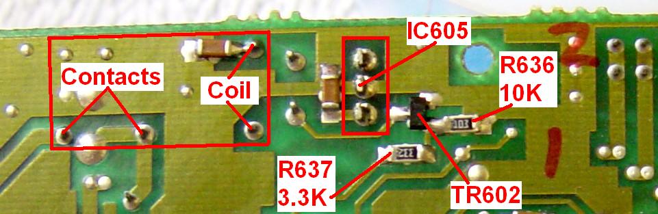
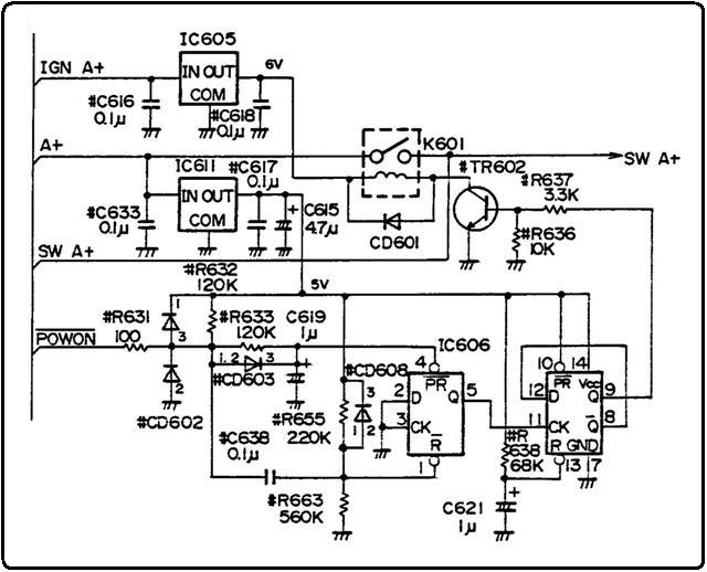
The power on/off control circuit is relatively simple. IC605 is a 6V, 3-terminal regulator that is fed by the Ignition wire through the power cable. This 6V supply is only used by the power control relay (K601) and the transistor that activates it (TR602). Activating the relay supplies power to the radio by routing incoming A+ power to outgoing SW A+ power. You can do this by shorting TR602's collector to emitter, or grounding TR602's end of the relay coil, thereby activating the relay all the time. This is a waste of power and could be a problem after years of continuous operation. Relay coils DO burn out. Shorting out the relay contacts is much more efficient. The remainder of the schematic deals with the front panel power button, which toggles the radio's power on and off via IC606 and TR602. Here's the power on/off control circuit schematic.
Other Notes:
You should program the radio for just one channel. That way, if the repeater should lose power, it will come back on the one and only channel that's programmed into it.
Let the transmitting radio encode Channel Guard, as it will handle Squelch Tail Elimination (STE) according to the programming data.
If you use the flat, unfiltered receive audio source, your repeater controller could decode Channel Guard (or Digital Channel Guard) itself rather than letting the receiver do it. I prefer to let the radio handle both the encoding and decoding chores.
The radio defaults to requiring Channel Guard signalling present on signals whose channels have it programmed. If you want to place the receiver into carrier-squelch mode, you can ground the microphone connector pin #7 (CG DSBL/TXD). This can be connected to an auxiliary output from your repeater controller.
Acknowledgements and Credits:
Channel Guard and CG are trademarks of Harris / MA/COM / GE / Ericsson, Inc, or whatever they're called these days.
Schematic information came from the relevant LBIs on repeater-builder.
All AC and DC voltage measurements were taken with a Fluke 189 digital multi-meter.
The initial nudge to write this article was provided by Len Kreyer N9QIP. It really was quite simple once I looked into it.
Contact Information:
The author can be contacted at: his-callsign [ at ] comcast [ dot ] net.
Back to the top of the page
Up one level (GE index)
Back to Home
This article created Sunday 04-Jan-2015.
Photographs, article text, and hand-coded HTML © Copyright 2015 by Robert W. Meister WA1MIK. All photographs were taken by the author unless otherwise indicated.
This web page, this web site, the information presented in and on its pages and in these modifications and conversions is © Copyrighted 1995 and (date of last update) by Kevin Custer W3KKC and multiple originating authors. All Rights Reserved, including that of paper and web publication elsewhere.