Back to Home
(or whatever corporate name is in use today)
MLS-II Mobile Radios
By Robert W. Meister WA1MIK

|
GE index Back to Home |
An Overview of the GE (or whatever corporate name is in use today) MLS-II Mobile Radios By Robert W. Meister WA1MIK |
|
The MLS-II radios are 2, 8, or 16 channel synthesized mobile radios, similar to the Motorola MaxTrac products. They come in VHF-low, VHF-high, UHF, and 800 MHz models with 30-40 or 60-watt power levels, depending on the band. 8 and 16 channel radios can be equipped for scanning.
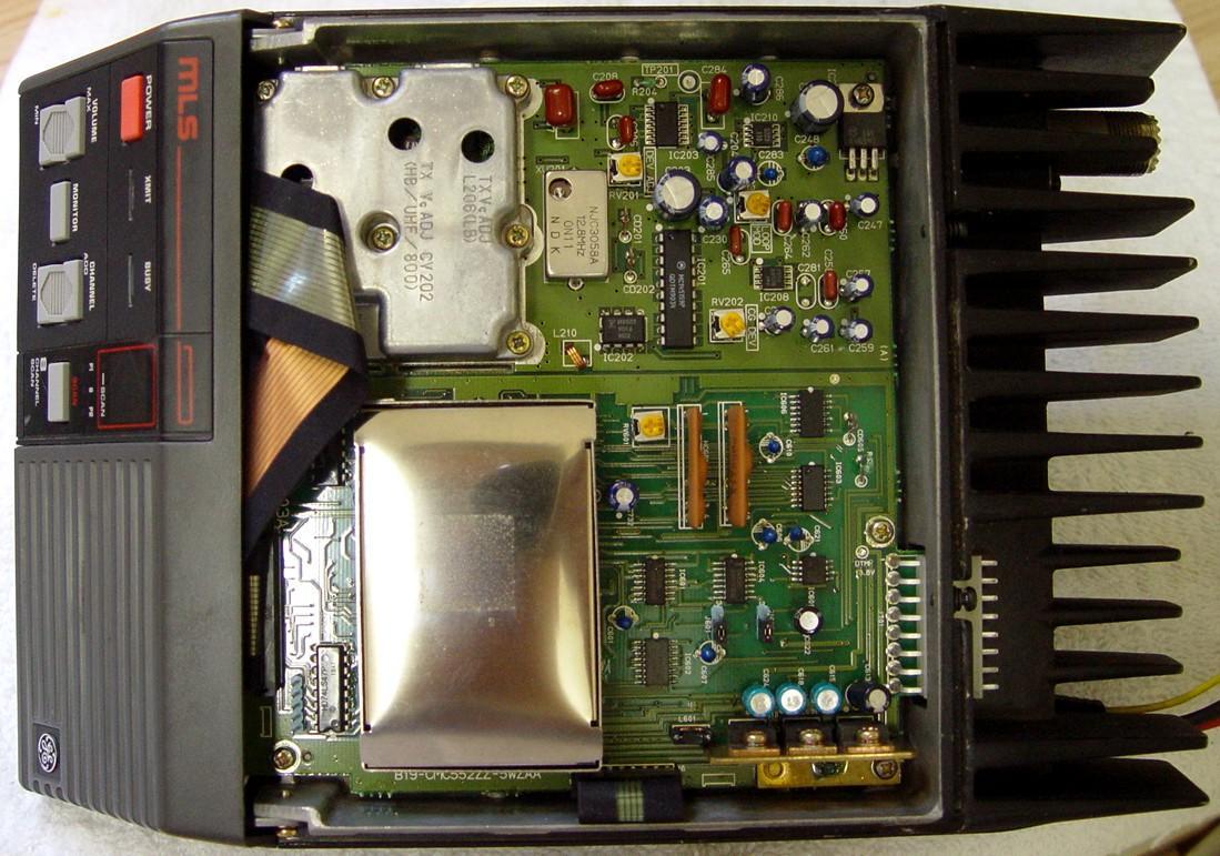
This overview is based on personal experience with my first MLSH041 VHF-high radio (8-channel, 150-174 MHz). I subsequently purchased an MLSL261 VHF-low radio (16-channel, 42-50 MHz), then an MLSU241 UHF radio (8-channel, 450-470 MHz), and just the other day a second MLSU241 UHF radio (also 8-channel, 450-470 MHz), all of which have scanning capabilities. I've had extensive experience with several MaxTrac models so my analysis may be somewhat biased. I shall compare these two radio series throughout this article. I've also done limited testing of these radios outside their specified range, particularly in the amateur bands. Here's a photo of the front panel of the radio (click on any photo to see a larger view):
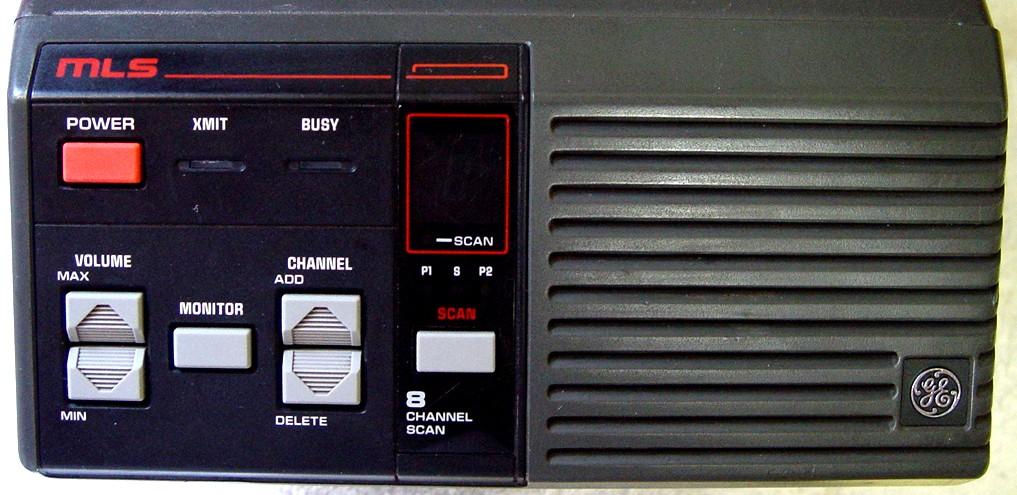
Although it's not obvious in this photo, the front panel faces upward at a 45-degree angle for easier viewing.
Model Number Breakdown:
The model number is a very logical seven-character string, broken down as follows.
| Product Code | Radio Type | Freq Band | Band Split MHz | TX Power | Generation |
|---|---|---|---|---|---|
| ML: always | S: synthesized | L: VHF-Low | 0: 150-174 or 800-870 | 3: 30 watts | 0: MLS |
| H: VHF-High | 1: 29.7-42 or 403-430 | 4: 40 watts | 1: MLS-II | ||
| U: UHF | 2: 42-50 or 450-470 | 6: 60 watts | |||
| 8: 800 MHz | 3: 450-470, 2.5ppm |
NOTES:
Based on the model information above, the following would be the possible legitimate MLS-II model numbers you'd see on radios:
MLSL161, MLSL261, MLSH041, MLSU141, MLSU241, MLSU341, MLS8031
The VHF and UHF radios only cover a small portion of the model's available frequency range. Apparently you must tune/align both VCOs in the radio for the narrower operating window it will be used in. In contrast, MaxTrac radios cover their entire sub-bands. The table below compares the various band splits and the maximum frequency spread or excursion. All numbers are in MHz.
| Freq Band | GE MLS-II | Motorola MaxTrac | ||
|---|---|---|---|---|
| Band Splits | Spread | Band Splits | Spread | |
| VHF-Low | 29.7-42, 42-50 | TX:1, RX:1 | 29.7-36, 36-42, 42-50 | Entire Split |
| VHF-High | 150-174 | TX:10, RX:5 | 136-162, 146-174 | Entire Split |
| UHF | 403-420, 450-470 | TX:10, RX:5 | 403-430, 449-470 | Entire Split |
| 800 MHz | 806-870 | Entire Band | 806-825, 851-870 | Entire Band |
Differences Between the MLS and MLS-II Radios:
Both radio series have the same channel and scanning capabilities and share the same accessories. The MLS radio has separate boards for the receiver and transmitter; the MLS-II radio combines the functionality onto one board. The circuitry and specifications are essentially identical; they're just arranged differently. The control panels are functionally identical but some signals are inverted.
The MLS-II radio does both CTCSS and DCS; the MLS radio only does CTCSS.
The MLS radio requires an external suitcase programmer and unique cable, which reads and writes the radio's EEPROM directly; the MLS-II radio uses an ordinary PC-compatible computer and a serial interface, similar to Motorola's RSS and RIB setup, and talks to the radio's microprocessor, which reads and writes the radio's EEPROM. You can immediately tell which radio you have by checking the last digit of the model number string: '0' for the MLS and '1' for the MLS-II. However, it's very easy to swap the control head housing, where the model number sticker is, so it's best to actually look inside and see what you have (I got burned that way once).
Accessories, Features, and Other Observations:
The microphone and programming cable use an 8-position Molex KK-series (0.156 inch) connector on the back of the radio. This is similar to the 5-pin accessory jack used on some MaxTrac radios (same pin size and spacing). The pin-out of this connector is listed in the table below. Pin 8 is closest to the outside edge of the radio. Pins 2 and 7 are also used by the serial programming cable. There is nothing to prevent you from plugging something in here with the connector shifted one way or the other. I did this by accident with my programming cable and it ended up feeding SW A+ into the TxD line, destroying the IC in the cable. A very poor design on GE's part.
| Pin# | Signal or Use | DCV | Notes |
|---|---|---|---|
| 1 | Speaker High | - - - | Always active |
| 2 | PTT / RxD | +5.0 | Ground for Transmit |
| 3 | Mic Low (Ground) | 0.0 | |
| 4 | Mic High (w/Bias) | +9.0 | Approx 80mV/kHz |
| 5 | A- (PTT Ground) | 0.0 | |
| 6 | Speaker Low | - - - | Selected via internal jumper |
| 7 | CG Disable / TxD | +5.0 | Ground for carrier squelch |
| 8 | Prog. Vcc (SW A+) | +13.8 | Not Fused ! |
The three-lead power cable (Ground, A+, Ignition Control) is permanently attached to the radio but terminates in a three-terminal polarized and locking Molex connector. My power cable was configured with both A+ and Ignition Control wired together, as it had been previously connected to an Astron RS-20 power supply.

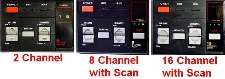
The model number doesn't indicate the number of channels or if the radio has scanning capability. However, a quick look at the front panel will tell you its capabilities, as they are all different and unique (unlike the MaxTrac). The channel display will be two discrete LEDs (2 channel), one seven-segment digit (8 channel) or two seven-segment digits (16 channel). Scanning is available if a SCAN button and four more LEDs are present. The channel capacity and scan ability is plainly marked as well. You must manually add or delete channels to the scan list via buttons on the front panel; there's no pre-programmed scan list. Priority channel scanning is possible. The montage below shows the differences.
The front panel circuit board has two lines that are sensed by the microprocessor, which it uses to determine whether the radio can support 2, 8, or 16 channels. The circuit boards do not have any provisions for expanding the channel capacity. The 8-channel board only has a single channel number digit while the 16-channel board has two. Scanning heads have an additional switch and four LEDs. The five circuit boards only contain enough circuitry to support the features they were designed for, so even if you trick the microprocessor into thinking it has a different front panel attached, you'll have no way to use the additional capabilities. The radio electronics and programming is the same for all models, except that scanning is optional on 8 and 16 channel radios and is never available on 2 channel radios. The table below describes the possible radio feature configurations for the five front panel circuit boards.
| #Ch | 2 | 8 | 8 | 16 | 16 |
|---|---|---|---|---|---|
| Scan | Never | No | Yes | No | Yes |
The scanned channel selection is only done via the front panel. These are retained when the radio is powered off or unplugged. The scan list is completely erased whenever the personality data is written to the radio with the programming software.
The microphone hang-up box (HUB) features a spring metal retainer that actuates a micro-switch inside the box when the microphone is inserted. This removes ground (coming from the power cable) going to the mike connector pin 7 to enable coded squelch when the mike is inserted in the HUB, i.e., supplying ground disables coded squelch. This is opposite to the way this works on the MaxTrac (and just about all Motorola radios), which grounds a pin on the mike connector to enable coded squelch when the mike is inserted into the HUB. With no microphone plugged into the rear connector (and no ground present on pin 7), the MLS radio defaults to coded squelch, whereas a MaxTrac defaults to carrier squelch. The front panel MONITOR button merely opens the squelch, disregarding any Channel Guard requirements. (I wouldn't be surprised if Motorola had a patent on the "ground to enable coded squelch" signal, so GE had to do just the opposite.)
As with the MaxTrac, a DC bias of about 9 volts is provided on the MIC High line to power the preamplifier inside the microphone. The PTT and CG Disable lines directly feed the microprocessor and are therefore 5VDC TTL signals. Switched A+ and a solid ground are also provided on the mike connector for powering a programming RIB or other accessory.
The internal or external loudspeaker can be selected via an internal jumper on the transmitter / receiver board on the underside of the radio. This supplies a ground to either the internal speaker or the SP-Low pin (#6) on the mike jack. Unlike the MaxTrac and several other Motorola radios, one side of the speaker IS truly grounded. You could attach an external speaker to the SP-High pin (#1) and the Ground pin (#5) and use both speakers at the same time, but you'd have to be careful about the load impedance.
The speaker in the MLS radio is considerably larger than the one in the MaxTrac radio. It sounds a lot better too. I monitored the local fire department frequency on each radio for a week; the MaxTrac has more punch and a narrower audio bandwidth, but the MLS was easier to listen to and had a more natural sound to it, at least in my quiet listening environment. While the radios have very similar audio frequency responses, measured at the speaker terminals, the smaller MaxTrac speaker seems to output more high frequency content than the MLS under similar conditions. This may be an asset in a noisy vehicle.
All of the front panel controls are silicone rubber, momentary pushbuttons, with a conductive carbon-impregnated contact button underneath, similar to the ones used on the MaxTrac. LEDs indicate when the radio is transmitting and when there is activity (a carrier) on the channel.
The electronic volume control changes the volume in 16 steps of 4.0dB each. The sound became audibly distorted at levels exceeding 5Vrms as measured on the SP+ and GND pins of the mike connector. This level exceeds the unit's rated 5 watts. It is very loud. The speaker is a lot bigger than what's found in most Motorola dash-mount radios.
The speaker audio is filtered to attenuate sub-audible signals below about 250 Hz. The higher frequencies follow the standard 6dB/octave de-emphasis curve.
These radios support both analog (CTCSS) and digital (DCS) Channel Guard (CG and DCG, GE's names for their coded squelch system). These are equivalent to, and compatible with, Motorola's PL and DPL coded squelch systems. Squelch Tail Elimination (STE) is GE's term for the Motorola-equivalent Reverse-Burst, and it can be enabled or disabled on each channel separately. With TX STE enabled, the transmitter stays on during the reverse burst and NO squelch tail is heard; with TX STE disabled, the transmitter shuts off the instant PTT is released and a squelch tail IS heard. RX STE operates somewhat uniquely. On a channel programmed with Channel Guard and RX STE enabled, the squelch tail is eliminated from a properly encoded transmission. With RX STE disabled, the squelch tail was also eliminated. When I grounded the mike jack's CG Disable pin, forcing the receiver into carrier squelch mode, the receiver still eliminated the squelch tail if RX STE was enabled, however the squelch tail was NOT eliminated with RX STE disabled. So it does seem to have an effect. Note that these two fields operate exactly the same with Digital Channel Guard: if TX STE is disabled, the turn-off code is not transmitted (resulting in a squelch tail at the receiver) and the transmitter ceases operation as soon as PTT is released. RX STE operates as described above. The following table summarizes the RX STE operation.
| RX STE | CG Pin | Effect on Received Signal |
|---|---|---|
| Enabled | Floating | Squelch Tail Eliminated |
| Disabled | Floating | Squelch Tail Eliminated |
| Enabled | Grounded | Squelch Tail Eliminated |
| Disabled | Grounded | Squelch Tail Present |
I captured the Channel Guard tone on my scope and analyzed it. In the two waveforms below, the top trace (red) is the PTT input (ground = transmit) and it triggers the scope where it rises (when the ground is removed) at the 2nd horizontal division. The bottom trace (blue) is the transmitted Channel Guard tone of 100.0 Hz. The first waveform shows that the tone reverses phase 26 msec after PTT is released. The phase reversal is between 130 and 135 degrees. GE seems to use 135 degrees on other radios. The programming manual just says the phase is inverted for Squelch Tail Elimination; that would imply a 180-degree shift, but it doesn't come right out and say that.
The second waveform shows that the phase-reversed burst lasts about 160 msec, then 30 msec later the radio switches from transmit to receive. The latter half of the blue trace is the detected receive signal (noise) that shares the Channel Guard circuitry. Obviously it doesn't affect the transmitted signal because the radio is no longer transmitting.
The analog CTCSS tone decoder, with 700 Hz deviation, had a ± 1.3 Hz acceptance window, i.e. it would decode a 100.0 Hz tone anywhere from 98.7 Hz to 101.3 Hz. The lowest level it would reliably decode was 160 Hz deviation. The acceptance window at that level was ± 1.5 Hz. The MaxTracs I've tested will often decode PL with deviation as low as 50 Hz. Nominal CTCSS deviation for wide-band (5 kHz) systems would be 500-1000 Hz.
The radio is programmed via the microphone connector on the back of the radio. The TQ-3343 radio cable is used with the MLS-II series. The radio's signals are TTL levels; they are converted to RS-232 levels for the computer via the TQ-3370 Radio Interface Box (RIB). The radio uses separate transmit and receive data lines so the programming software can operate full duplex, unlike the MaxTrac that shares one data line for both signals, letting the RIB sort it out. The GE RIB is merely a TTL to RS232 level converter. At least one company makes a programming cable with the interface built into the DE-9 connector (a so-called RIB-less cable) as one assembly. GE, like Motorola, provided radio-specific programming cables and several RIBs for use with their synthesized equipment. Here's a schematic of the TQ-3343 RIB-to-radio cable:
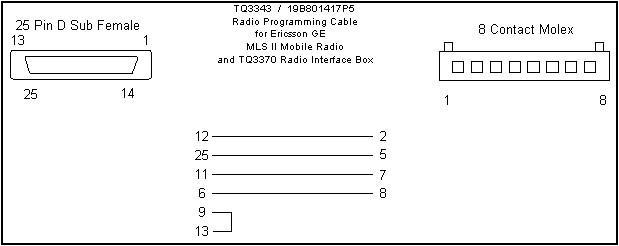
I purchased a pre-made MLS-II RIB-less programming cable for $50US from Price Industries. Yes, I could have made one for about $15 in parts plus my labor to assemble and test it, but I opted to buy one ready to go and save the aggravation. I purchased the cable on a Saturday morning and received it Monday afternoon. It even had free USPS Priority Mail shipping. I can't complain about that one bit. The quality was excellent and it worked the very first time. Inside the metal DE-9 connector shell is a tiny circuit board with several SMD components mounted on it: a MAX202CSE+ RS-232 level converter, several electrolytic capacitors, and a 5V regulator.
Update October 2012: the link for Price Industries, and in fact the company itself, seems to have vanished. I found what seems to be a suitable replacement cable here. After damaging my Price Industries cable, I purchased one from RF Guys in August 2013; it works but I will be returning it for several reasons shown in the table below. If it was the only cable I had, it's certainly better than nothing.
| Parameter | Price Industries Cable | RF Guys Cable |
|---|---|---|
| Power Source | +12V from radio | Serial port |
| PTT Activated | When computer shut off | When cable is attached to radio |
| Cable | Round; 4 thick wires | Flat; 3 thin wires |
| Radio Connector | Molex, with handle | Molex, no handle |
| Strain Relief | Yes, on handle | None |
| Cable Length | 70 inches | 31 inches |
| DE-9 Housing | Metal | Plastic |
Alignment and tuning adjustments are made using well-labeled potentiometers, coils, and trimmer capacitors located on the transmitter / receiver board and the system control / synthesizer board. Unlike Motorola, you don't need RSS to align this radio, just the appropriate test equipment and a small screwdriver or straight-bladed plastic alignment tool. If the deviation is set for 4.25 kHz on voice, and the Channel Guard deviation is set for 0.75 kHz, the total deviation will be 5.0 kHz on a CG-enabled channel and 4.25 on a non-CG-enabled channel (i.e., they don't/can't change the total deviation based on the presence or absence of CG, as is done on the MaxTrac).
The mounting bracket attaches to the radio with four M4x0.7 screws.
My VHF-High radio output 42 watts, drawing 10.5 amps at 14.0 volts. The frequency was less than 400 Hz low on the channel I measured. Sensitivity was better than 0.3µV for 20dB quieting. The radio immediately protects itself when transmitting into an improper or missing antenna. These radios sense PA temperature, PA current, and both the forward and reflected power. It uses these to protect the PA and maintain the desired transmit power, regardless of operating conditions (to the best of the radio's ability). The MaxTrac radios only sense the PA current and the entire radio's temperature.
My VHF-Low radio output about 60 watts, drawing 11.5 amps at 14.0 volts. The frequency was 5 Hz low on the channel I measured. Sensitivity was about 0.3µV for 20dB quieting. All of the programmed frequencies were in the 47.0 to 47.5 MHz portion of the band.
As received, my UHF radio output about 32 watts, drawing 7.5 amps at 14.0 volts. The transmit frequency was 1 kHz low; the receive frequency was almost 2 kHz low. Sensitivity was about 0.4µV for 20dB quieting.
Issues With My VHF-High Radio:
There's a low-frequency (100 Hz) hum present on the speaker audio, even on un-modulated carriers, so I suspect there's a problem with this particular radio. Upon further inspection, I can see a 99.7 Hz square wave on the incoming A+ power lead, and that goes directly to the audio power amplifier. It becomes audible when the squelch opens and the amplifier un-mutes. The volume control doesn't change the level, so it's just limited to the audio PA circuit. I can see square wave signals feeding the front panel display at exactly the same frequency. I suspect bad capacitors in the regulator section as at least one of them has leaked and has high resistance. Replacements have been ordered.I also discovered that an over-voltage protection component, a metal oxide varistor (MOV) under the PA shield, had caught fire and burned up. It spewed some nasty tar-like substance and the smoke discolored several nearby components. Nothing else was permanently damaged, but I suspect the radio had been subject to excessive voltage at some time in its life. Everything seems to be working fine except for the hum mentioned above.
Final follow-up: replacing four capacitors around the power supply regulators completely eliminated the hum. This is by far the quietest radio I've ever heard. There's a lot less background hiss than I usually hear in similar MaxTrac radios. I can't even tell the radio is un-squelched with a 1000µV carrier feeding it; the un-modulated noise on the speaker leads is over 50dB quieter than with full system modulation. While I had the radio apart, I also installed a new MOV and performed a full alignment, so it's back to stock.
Issues With My VHF-Low Radio:
I had two minor mechanical problems (annoyances) with this radio. The Molex power connector on the end of the short power cord that comes out of the radio was missing. It had been cut off and just bare wires remained. I'll be installing the correct Molex three-pin connector (Mouser part number 538-50-84-2030) and three male pins (Mouser part number 538-02-08-2004). Also, the Molex mike connector on the back of the radio is supposed to have a plastic latch piece; this had been broken off. The connector's pins are now fully exposed. It works fine, but I'll order a new one (Mouser part number 538-26-60-5080) and replace it. Neither of these conditions prevents the radio from being used; it's just the chance you take when you receive a second-hand unit.
Issues With My 2nd VHF-Low Radio:
This was a 2ch model with all the accessories and was dirt-cheap. It was also quite dirty on the outside. It had rather poor sensitivity (-107dBm for no crackles), the 100.0 Hz CG decoder didn't work, and the front panel buttons were intermittent. It had the same 100 Hz hum/buzz that the other radios had, and four new capacitors fixed that up. All of the 47uF caps were bad, either open or high ESR.
After replacing the caps, the receiver sensitivity came back to a respectable -117dBm and the CG decoder worked properly. The front panel just took a good cleaning, first with soap and water, then with alcohol. Output power was 56 watts and the unit was within 60 Hz of the correct frequency of 45.7600 MHz. I realigned the receiver and improved the sensitivity to -121dBm for no crackles (around 20dB quieting).
Issues With My UHF Radio:
This radio was purchased as-is, for parts or repair. I found nothing mechanically wrong with it and it was very clean.
Like my VHF-high radio, this one also had a 100 Hz hum on the speaker audio, so I just pulled the circuit board and replaced the same four capacitors around the power supply regulators. I haven't measured them, but at least one was already leaking (C624, the filter capacitor for the 5V supply that runs the display). The hum is now gone.
I adjusted the transmit and receive frequencies and raised the output power to 35 watts. The radio now works perfectly.
Issues With My 2nd UHF Radio:
This radio was also purchased as-is, for parts or repair. I couldn't resist the price: $0.99 plus shipping, and it came with a desk microphone, a short power cord, and a right-angle UHF adapter for the antenna jack. The front panel was dirty. I took it all apart, cleaned it thoroughly, and cleaned the switch contact areas of the circuit board with alcohol. The rest of the radio was clean inside and out.
This radio had a weak 100 Hz hum on the speaker audio, but it also had a noticeable hiss coming out of the speaker during transmit. I replaced the four capacitors around the power supply regulators and both problems have disappeared. I measured all four caps as being up to 5% high on value and they all had an acceptable ESR (Equivalent Series Resistance) of under 0.5 ohms. None of them showed any signs of leakage.
The radio put out 35 watts, was 15 Hz low in frequency, had 4.8 or 4.2 kHz deviation (with and without CG), and had no crackles on a received signal of 0.33µV. Even the desk microphone seems to be working just fine.
What's Under the Hood:
(References to upper, lower, top, bottom, left, or right, are as the images/photos are viewed on your screen.)
Loosen two screws at the rear and remove the top cover to get you to the system control / synthesizer board. The microprocessor, program memory, and user personality memory are located in the shielded compartment of the lower half. The transmit audio circuitry is located on the upper half, with the VCO under the shield at the left and the temperature-compensated reference oscillator right next to it. There are pots here for overall deviation, Channel Guard deviation, and loop modulation, all nicely labeled. The power supply voltage regulators are in the lower right corner, and the four capacitors directly above them are the ones I ended up replacing on my unit. The front panel cable, seen folded at the left side of the image, plugs into this board.
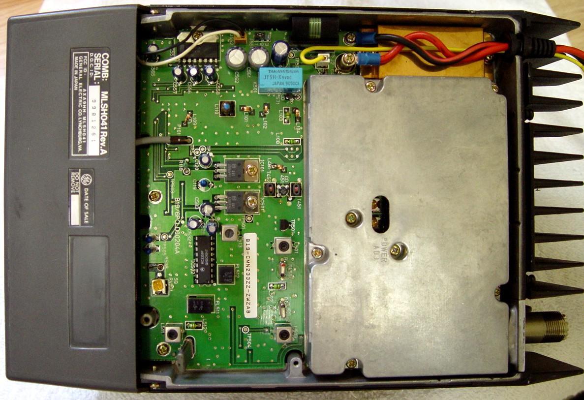
Loosen two more screws at the rear to remove the bottom cover to get you to the transmitter / receiver board (a high-band radio is shown below). There are pots here for squelch and output power, also well labeled. Along the top edge of the board you can see the audio amplifier IC, the front panel speaker leads and connector, and the jumper that selects the internal or external loudspeaker. The copper shield covers the RF driver module on those radios that use them, while the entire RF power amplifier, receiver front end, RF amplifier, and pre-mixer filters are under the aluminum shield. All of the power leads are easily detached. One flat cable and one coax jumper connect this board to the one on the other side of the chassis. The UHF radio is just about identical in appearance, with the same copper-shielded RF driver module and large aluminum shield.
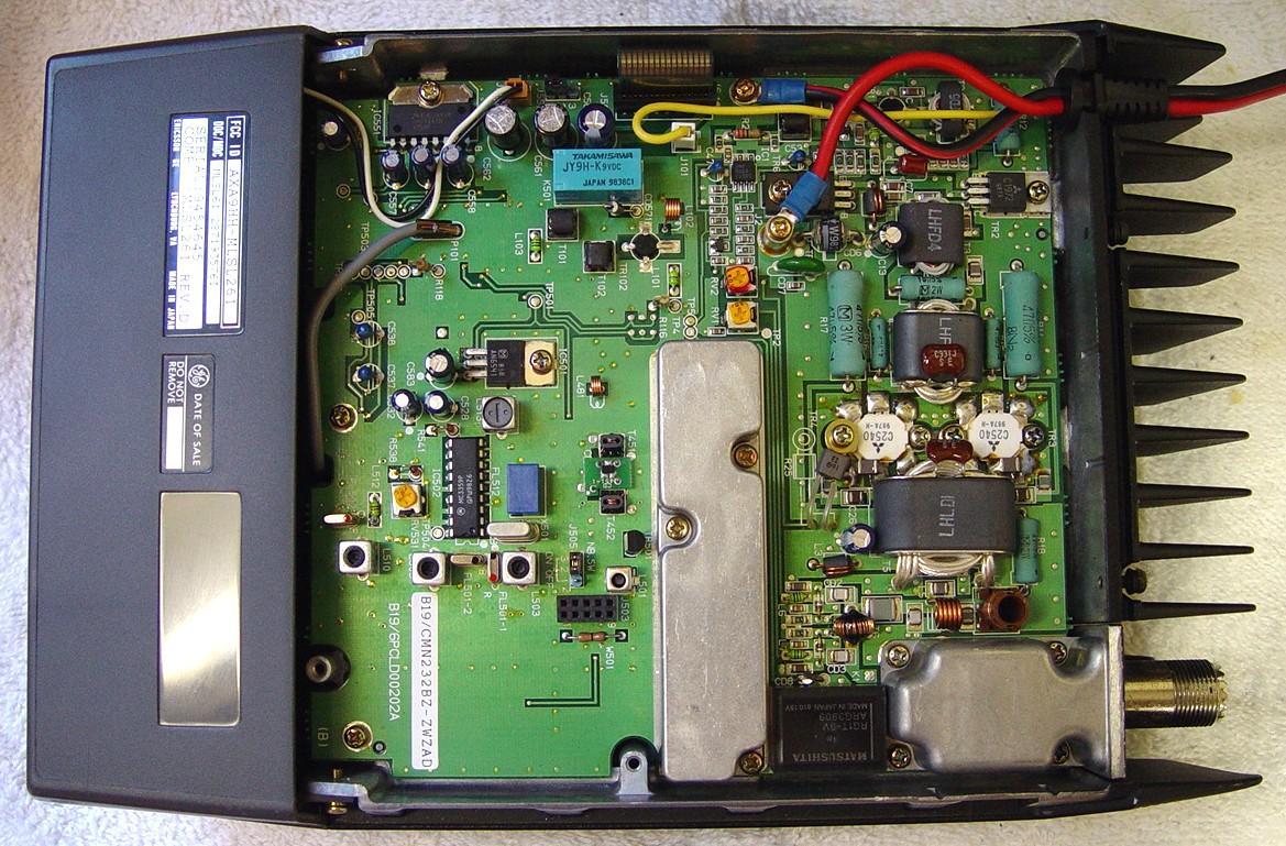
The low-band radio is divided up the same way (all of these radios are very modular in design), however the transmitter / receiver board is noticeably different, as seen in the photo below. The shielded area in the middle houses the receiver front end, RF amplifier, and pre-mixer filtering; the PA is not shielded. The 10-pin connector to its left is for the optional noise blanker. The cast shield behind the SO-239 antenna connector covers the low-pass filter. A similar shield is found on the VHF-high radio although it's under the much larger PA shield and can't be seen in the photo above.
Four screws (two on each side) hold the front panel assembly to the chassis. The speaker and control panel are held in place with a few self-tapping screws and some plastic clips. All of the hardware in the radio is Metric thread, Phillips-head; no Torx drivers to deal with.
The radio's heat sink is massive and amply finned. This may be why it is rated for 20% duty cycle. The main chassis is one piece of milled aluminum. Over a dozen screws hold each board to the chassis.
The two covers are different lengths, so they can only be replaced the right way.
Documentation:
There's one "combination" manual for each band, which lists the individual major assembly manuals. Each major assembly (system control / synthesizer board, transmitter / receiver board, front panel) has its own manual (LBI), depending on the frequency band of the radio. There are also frequency-dependent service manuals that cover maintenance and alignment.
Rather than transcribing existing work, here's a link to a page that lists all the manual numbers; it came from the Doug Hall Electronics web site. Many of the manuals can also be found in the GE section of Repeater-Builder.
Specifications:
It makes sense to compare this radio to its competition: the Motorola MaxTrac. The specifications and features in the list below were taken from the appropriate manuals. Actual test results taken by the author are shown in parentheses. Parameters that are the same for both radio series have been omitted.
| Parameter or Feature | GE MLSH041 | Motorola D43 |
|---|---|---|
| Width | 7 inches | 7 inches |
| Height | 2-1/2 inches | 2 inches |
| Depth | 11 inches | 8 inches |
| Weight | 2.7 kg | 1.7 kg |
| Duty Cycle | 20% TX | 10% TX |
| VHF Frequency Range | 150-174 (or more) | 146-174 (or more) |
| Actual Band Coverage | TX: 10, RX: 5 MHz | Entire band |
| VCO Tuning | Required | Not Necessary |
| Receiver Tuning | Required | Not Necessary |
| Channel Spacing | 30 kHz | 30 kHz |
| Off Current | 0.03A (0.01A) | --- (0.005A) |
| RX Current | 0.7A (0.5A) | 0.4A (0.35A) |
| TX Current | 14A (10A) | 12.5A (9A) |
| Audio Out @ 5% distortion | 4 watts | 3 watts |
| RX Sens. 12dB SINAD | 0.35µV | 0.30µV |
| RX Sens. 20dB Quieting | 0.40µV (<0.30µV) | --- (<0.30µV) |
| Selectivity | -70dB | -80dB |
| Maximum Channels | 16 | 32 |
| Antenna Switching | Relay | Solid-state |
| Antenna Jack | UHF | Mini-UHF |
| Power Switching | Relay | Mechanical Switch |
| Volume Control | Electronic | Mechanical Pot |
| External Accessory Jack | No | Yes |
| Microphone Connector | Molex KK 0.156 | RJ-45 modular |
| Hang-up Mechanism | Ground for CSQ | Ground for Coded |
| Speaker Selection | Internal Jumper | External Jumper |
| Alignment Adjustments | Mechanical | Via Software |
| Low-band Noise Blanker | Optional, always on | Built-in, switchable |
After programming one channel to 144.0 MHz, the radio performed just as well as it did on a 154 MHz frequency. Output power was 45 watts and the 20dB quieting sensitivity was 0.266µV. This radio has "ham-friendly" frequency coverage.
This VHF MLS radio had substantially less audio distortion at the loudspeaker than a VHF MaxTrac radio, at all tested frequencies and deviation levels. However, the MaxTrac had slightly less distortion at lower signal levels (in the 0.1 to 1.5µV range) than the MLS.
Programming Software:
The programming software is product number TQ-3342. The table below summarizes the allowable transmit frequencies and step size (or increment) in the MLS.EXE program.
| Band | Ranges in MHz | Step Size in kHz |
|---|---|---|
| VHF-L | 29.7-42.0 | 5 |
| VHF-L | 42.0-50.0 | 5 |
| VHF-H | 150-174 | 5 or 6.25 |
| UHF | 403-420 | 6.25 |
| UHF | 450-479 | 6.25 |
| 800 | 806-825 | 12.5 |
| 800 | 851-870 | 12.5 |
The programming software I had available was Version 1.0; a newer version exists. It's a DOS program but it can be started under Windows (I don't know if it runs properly with a radio that way). I copied it to my programming computer (a Pentium 100 laptop), plugged the RIB-less programming cable into the DE-9 jack on the computer and into the MIC jack on the back of the radio, turned the computer and radio on, and started the program. Without doing anything else I was able to read the existing personality from the radio and save it to the computer's hard drive. The program was already configured for COM1 and a color screen.
When the software is reading or writing data to the radio, the channel display showed "0" (or "00" on the 16-channel radio), which is the only indication that the program is actually doing something. On a 2-channel radio, both channel LEDs light up.
After using many Motorola RSS programs, this one wasn't much different. You can read a personality (equivalent to Motorola's "code plug"), create a new one from scratch (that's a nice feature that RSS doesn't have), program the radio with it, make changes to an existing one, etc. There's an option to print the personality data. As the radio is aligned with mechanical pots, there's no Service menu.
You can press F9 at just about every field or screen to get a short help text.
The one annoying thing I discovered is that pressing the TAB key moves you around the various numeric fields but it toggles any YES/NO fields. You really need to use the ENTER key or the arrow keys to navigate around the screen, and leave the TAB key for toggling only. Also, you need to tell the program what you want to do (read, write, change, etc.) first; then it asks you which personality you want to work with. Most Motorola programs require you to select the code plug first, then decide what you want to do with it.
The primary personality data screen shows all of the fields for each channel on one line:
The program rejected any attempt to enter a frequency lower than 150 MHz for my high-band radio, however by terminating data entry with CTRL-E rather than ENTER the program accepted an out-of-range frequency value (similar to the SHIFT-NUM method that works on many of Motorola's RSS programs). It was also difficult to delete a channel's data; I had to press the DEL key numerous times to erase the data in the field. Eventually I found out that pressing CTRL-BACKSPACE clears all of the data to the left of the cursor.
The programmable frequency limits (using CTRL-E) seem to be 10 MHz above or below the legitimate frequency range for the radio.
When entering frequency data into an empty channel, the transmit frequency is automatically copied into the receive field. On 800 MHz radios, if the transmit frequency is between 806 and 825 MHz, the receive field will be filled in with a frequency that's 45 MHz higher.
Analog Channel Guard tone frequencies have a decimal point in them, while digital Channel Guard codes do not. The software (and radio) will accept any frequency between 50.0 and 255.0, including non-standard tones (by using CTRL-E to terminate data entry). There's no provision to enter the two-character Motorola tone codes, such as 2A, 4Z, etc. Here's the list of the valid Channel Guard tone frequencies:
67.0, 71.9, 74.4, 77.0, 79.7, 82.5, 85.4, 88.5, 91.5, 94.8, 97.4, 100.0, 103.5, 107.2, 110.9, 114.8, 118.8, 123.0, 127.3, 131.8, 136.5, 141.3, 146.2, 151.4, 156.7, 162.2, 167.9, 173.8, 179.9, 186.2, 192.8, 203.5, 210.7
Inverted digital codes start with the letter "I". Only valid digital Channel Guard codes are accepted. The programming manual has a list of the valid codes, equivalent codes, and inverted codes, but strangely it only goes up to 526; I know that digital coded squelch codes can range from 000 to 777.
After making changes to the personality, I decided to write the modified version back to the radio. I was prompted to save it first (which I did using a different name); then the radio went into programming mode as the software sent it the data. After the data was sent, apparently it was read back and compared (verified) to make sure it actually got there correctly. This is a nice touch. It took 10 seconds to write the data to my 8-channel radio and another 10 seconds to verify it.
My radio only had seven channels programmed into it when I got it. All channels were scanned when I pressed the SCAN button. After writing a modified personality to the radio, SCAN no longer worked. I did not see a scan list within the software, so I suspect I would have had to add or select channels manually via the front panel. (I confirmed that the scan list, entered via the front panel, is cleared after the program writes the personality to the radio.) When I added the eighth channel (162.4 MHz), the display would flicker when channel 8 was selected. After deleting the 8th channel and reprogramming the radio, it returned to normal. I later found out this is the radio's way of telling the operator that the VCO has not locked up and the frequency is out of range. I guess the radios do not cover the entire 150-174 MHz band without some retuning.
WARNING! If you unplug your programming cable from the computer, or turn your programming computer off with the programming cable still plugged into the radio, the PTT/RxD line momentarily goes to ground, causing the radio to transmit for a split second. This could cause damage to whatever is connected to the antenna jack at the time. Turn the radio off before turning the programming computer off or unplugging the cable. The radio should be the last thing you turn on and the first thing you turn off. Don't disconnect any programming cables or cycle power on any attached device with the radio turned on.
Other Items Worth Noting:
The low-band radios can be equipped with an optional noise blanker, similar to the Extender circuit built into most Motorola low-band mobile radios (including the MaxTrac). It operates on the internal 20.8 MHz IF signal and can only be disabled via an internal jumper. My MLSL261 radio did NOT have this module installed.
The 800 MHz radios don't have a talk-around button, but simplex frequencies can be programmed into the personality data.
The 800 MHz radio has an N-female antenna connector. All the other models have a UHF-female antenna connector.
I've been told that 800 MHz MLS-II radios can be used in the 900-940 MHz range. You tell the programming software that the radio is in the 450-470 MHz band and enter frequencies that are exactly half of the desired 900 MHz frequency, since the VCO output is followed by a doubler inside the radio. I presume that the receiver sensitivity in the amateur portion of the band is severely reduced by the ceramic filters used in the front end.
Low-band Performance Outside 42-50 MHz:
After testing the radio at its 47 MHz frequencies, I measured the VCO control voltage (RX: 5.5-5.7V, TX:5.2-5.5V), receiver sensitivity (-117dBm), transmitter output power (60 watts), and current (11.5 amps). I then programmed the radio with frequencies from 49 to 55 MHz. Needless-to-say, the VCOs did not lock up on every channel. Per the information in the service manual, I unplugged the coax cable from the VCO (to keep it from transmitting until I was sure it wouldn't harm the radio) and adjusted both VCOs for 7.0VDC at 55 MHz. A quick transmit test revealed that on frequencies above 51 MHz, the radio was drawing more current than my power supply could provide, so I reduced the output power from 60 watts (and 11.5 amps) to 30 watts (and 7.0 amps) at 49 MHz, the lowest frequency. I then measured and recorded the VCO control voltages, receiver sensitivity, transmitter output power, and DC current on each channel and tabulated the results. In the table below, Freq is in MHz, RXV and TXV (the VCO control voltages) are volts DC, Sens is dBm, Pwr is in watts, and Cur is amps DC.
| Freq | RXV | TXV | Sens | Pwr | Cur |
|---|---|---|---|---|---|
| 49 | 4.65 | 3.68 | -117 | 30 | 7.0 |
| 50 | 5.05 | 4.39 | -117 | 30 | 7.4 |
| 51 | 5.43 | 5.00 | -117 | 30 | 8.0 |
| 52 | 5.80 | 5.50 | -117 | 28 | 8.8 |
| 53 | 6.19 | 6.00 | -116 | 26 | 9.0 |
| 54 | 6.58 | 6.50 | -114 | 20 | 8.5 |
| 55 | 7.00 | 7.00 | -113 | 15 | 6.7 |
The two VCOs had plenty of adjustability above 50 MHz. They could probably go higher still. Both of them ended up operating in their legitimate range, even over the 7 MHz spread I had set up. Obviously this far exceeds the 1 MHz frequency spread listed in the specifications, which is a good thing. The limiting factor was the transmitter and receiver. The radio seemed to perform just fine up to 52 MHz, but then started losing receiver sensitivity and transmitter output power. I suspected the low-pass filter behind the antenna connector is the culprit, but it measured good up to 55 MHz so I'm not going to worry about it. If you reduce the output power, then this radio should be quite usable through the 6-meter amateur band. Efficiency drops off above 52 MHz and I'm sure the radio would get hot if used here for any long-winded transmissions. Of course, the deviation should be readjusted if you move the operating range this far.
There are only two small air-wound coils under the front-end shield that could be fiddled with. In comparison, the MaxTrac has nine slug-tuned coils (without slugs) that one can insert brass screws into, to improve the sensitivity above 50 MHz.
The transmitter, on the other hand, has very few coils that can be fiddled with, and I'm sure the ones used in the low-pass filter are similarly hard-to-modify air-wound coils. Plus they're under a shield that has screws holding it to the circuit board from underneath so it's not trivial to remove just the shield.
I also tested the radio in the 37-43 MHz range. I adjusted both VCOs for 7.0VDC at 43 MHz, the highest frequency. The receive VCO control voltage was 2.3V at 37 MHz and the transmit VCO would not lock up there, having reached 2.6V at 38 MHz. I suspect it would have operated at 37 MHz if I adjusted the VCOs for 7.0V at a lower frequency. The receiver sensitivity was identical to what it was in the 42-50 MHz range: -117dBm for 20dB quieting (no crackles). It seemed that the receiver was just starting to lose sensitivity at 37 MHz. Output power stayed at a constant 60 watts at 11.5 amps, however the current dropped off a bit to 10.5 amps below 40 MHz.
High-band Performance Outside 150-174 MHz:
After testing the radio at its 154 MHz frequencies, I measured the VCO control voltage (RX: 5-7V, TX: 5-7V), receiver sensitivity (-118dBm), transmitter output power (40 watts), and current (10.2 amps). I then programmed the radio with frequencies from 141 to 150 MHz. Surprisingly, the receive VCO locked up on every channel and the transmit VCO needed a slight adjustment for frequencies below 143 MHz. (I suspect the VCOs were previously adjusted around 156 MHz.) I measured and recorded the VCO control voltages, receiver sensitivity, transmitter output power, and DC current on each channel and tabulated the results. In the table below, Freq is in MHz, RXV and TXV (the VCO control voltages) are volts DC, Sens is dBm, Pwr is in watts, and Cur is amps DC.
| Freq | RXV | TXV | Sens | Pwr | Cur |
|---|---|---|---|---|---|
| 150 | 4.96 | 4.97 | -118.0 | 40 | 10.3 |
| 149 | 4.65 | 4.58 | -118.0 | 40 | 10.4 |
| 148 | 4.39 | 4.20 | -118.0 | 40 | 10.5 |
| 147 | 4.12 | 3.83 | -118.0 | 41 | 10.7 |
| 146 | 3.87 | 3.47 | -118.0 | 41 | 10.9 |
| 145 | 3.63 | 3.12 | -118.0 | 41 | 11.0 |
| 144 | 3.41 | 2.78 | -118.0 | 41 | 11.2 |
| 143 | 3.20 | 2.46 | -118.0 | 42 | 11.5 |
| 142 | 2.99 | Adj. | -117.5 | 42 | 11.6 |
| 141 | 2.79 | Adj. | -117.5 | 42 | 12.0 |
The two VCOs had plenty of adjustability below 150 MHz. They could probably go lower still. Both of them ended up operating in their legitimate range, even over the 10 MHz spread I had set up. This radio exceeds the 10 and 5 MHz frequency spreads listed in the specifications, which is a good thing. The radio seemed to perform just fine down to 144 MHz, but then started losing receiver sensitivity very slightly. The transmitter seemed quite happy to operate below 150 MHz. Of course, the deviation should be readjusted if you move the operating range this far.
I did not bother testing the radio above 174 MHz, but I suspect it would have gone several MHz higher if I tried it.
UHF Performance Outside 450-470 MHz:
After testing the radio at its 460 MHz frequencies, I measured the VCO control voltage (RX: 4.8-5.4V, TX: 4.1-5.7V), receiver sensitivity (-114.5dBm), transmitter output power (35 watts), and current (9.0 amps). I then programmed the radio with frequencies from 441 to 450 MHz. Needless-to-say, the VCOs did not lock up on every channel. Per the information in the service manual, I unplugged the coax cable from the VCO (to keep it from transmitting until I was sure it wouldn't harm the radio) and adjusted both VCOs for 7.0VDC at 450 MHz. I then measured and recorded the VCO control voltages, receiver sensitivity, transmitter output power, and DC current on each channel and tabulated the results. In the table below, Freq is in MHz, RXV and TXV (the VCO control voltages) are volts DC, Sens is dBm, Pwr is in watts, and Cur is amps DC.
| Freq | RXV | TXV | Sens | Pwr | Cur |
|---|---|---|---|---|---|
| 450 | 7.01 | 6.91 | -114.5 | 35 | 8.6 |
| 449 | 6.72 | 6.60 | -114.0 | 35 | 8.8 |
| 448 | 6.44 | 6.30 | -114.0 | 35 | 8.9 |
| 447 | 6.16 | 6.01 | -114.0 | 35 | 8.9 |
| 446 | 5.88 | 5.72 | -114.0 | 35 | 8.9 |
| 445 | 5.61 | 5.43 | -114.0 | 35 | 8.9 |
| 444 | 5.35 | 5.16 | -113.5 | 35 | 9.0 |
| 443 | 5.09 | 4.89 | -113.5 | 35 | 9.0 |
| 442 | 4.84 | 4.63 | -113.0 | 35 | 9.0 |
| 441 | 4.59 | 4.37 | -113.0 | 35 | 9.0 |
The two VCOs had plenty of adjustability below 450 MHz. They could probably go lower still. Both of them ended up operating in their legitimate range, even over the 10 MHz spread I had set up. This radio exceeds the 10 and 5 MHz frequency spreads listed in the specifications, which is a good thing. The radio seemed to perform just fine down to 445 MHz, but then started losing receiver sensitivity very slightly. I suspect the ceramic band-pass filter used in the receiver; there's nothing I can do about that. The transmitter seemed quite happy to operate below 450 MHz. Of course, the deviation should be readjusted if you move the operating range this far.
I did not bother testing the radio above 470 MHz, but I suspect it would have gone several MHz higher if I tried it.
Acknowledgements and Credits:
Doug Hall's site seems to have the most information on the MLS radios. Highly recommended.
Channel Guard, CG, and DCG are trademarks of Harris / MA/COM / GE / Ericsson, Inc, or whatever they're called these days.
RSS, PL, DPL, and MaxTrac are trademarks of Motorola, Inc.
Thanks go to Mike WA6ILQ for reading the article, asking questions, and suggesting additional material.
I received additional information from Mark KB4CVN and I am very thankful for it.
Contact Information:
The author can be contacted at: his-callsign [ at ] comcast [ dot ] net.
Back to the top of the page
Up one level (GE index)
Back to Home
This page originally posted on Monday 14-Jun-2010.
Photographs, article text, and hand-coded HTML © Copyright 2010 by Robert W. Meister WA1MIK. All photographs were taken by the author unless otherwise indicated.
This web page, this web site, the information presented in and on its pages and in these modifications and conversions is © Copyrighted 1995 and (date of last update) by Kevin Custer W3KKC and multiple originating authors. All Rights Reserved, including that of paper and web publication elsewhere.