Back to Home
Radios in Repeater Service
By Robert W. Meister WA1MIK

|
GE index Back to Home |
Using GE MLS-II Mobile Radios in Repeater Service By Robert W. Meister WA1MIK |
|
A few people have inquired about using GE MLS radios as repeater receivers or transmitters. I had briefly looked into it but since I didn't need to use them in that situation, I didn't go any further. Perhaps others have successfully converted them. I have used Motorola MaxTrac, Radius, and GM300 mobile radios as repeater receivers and transmitters and they work great. Since the MLS-II is so similar, I asked myself "How hard can it be?"
I used a VHF-HI radio (MLSH041) for this article because the available documentation (LBIs) on this site is the clearest for that particular radio. The RF board on other bands will be similar; the command board and microphone connector are identical. Many of the same signals exist on the MLS-I radio but the documentation for those is barely legible.
Program and align your radio and verify proper operation before attaching any wires to it. You can bring the necessary wires out the back next to the microphone connector.
Click on any photo to see a larger image.
Required Signals:
To interface mobile radios to most repeater controllers, you need several signals:
The following paragraphs show where I found these signals and gives specific AC and DC voltages, where applicable.
Transmit Audio Input:
The simplest and easiest place to get this is on the rear 8-pin Molex microphone connector at pin #4 (MIC HI). There is +9.6VDC present here to power the preamp built into most GE microphones, so you will need to use a coupling capacitor of 10 uF at 16V (or larger) between this point and your repeater controller. The input impedance is around 680 ohms. The audio will be pre-emphasized. You will need approximately 70 mV per 1 kHz of deviation at 400 Hz, depending on how you have set the deviation control.
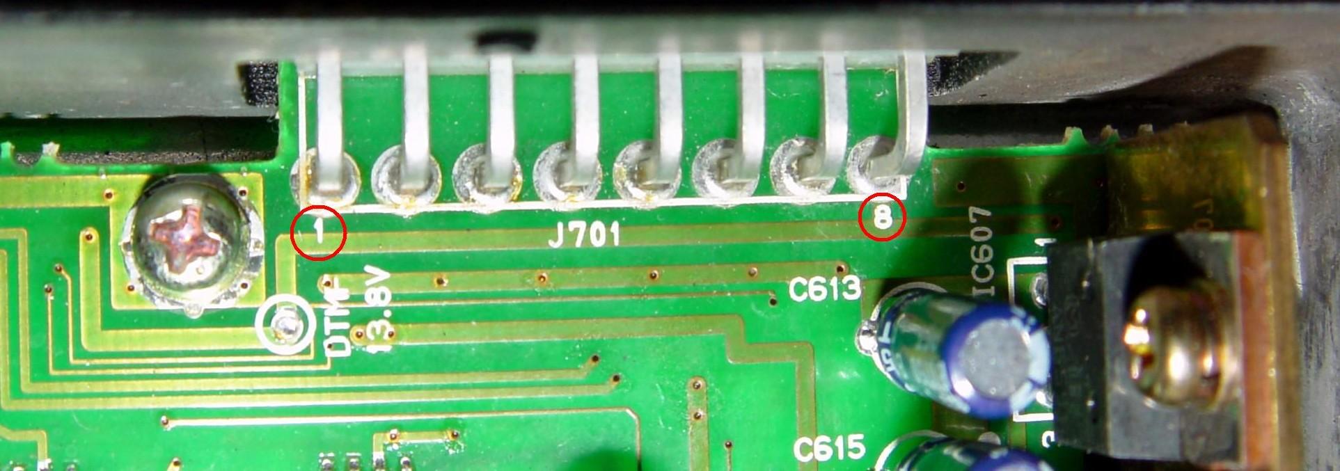
Note that pin #8 is closest to the edge of the chassis. The mating Molex connector can be installed either way and even offset by one pin left or right. Make sure it's well labeled so it can't be installed incorrectly. Pin #8 has unfused switched +13.8VDC on it and anything connected to that pin will have nearly unlimited current available to it when the radio is turned on.
PTT Input:
This is also one of the easy ones to get on the rear 8-pin Molex microphone connector at pin #2 (PTT/RXD). This pin sits at +5VDC and you bring it to ground to cause the radio to transmit. This pin will require about 0.5 mA of current, which can be supplied by a transistor, IC, or relay contact.
Receive Audio Output:
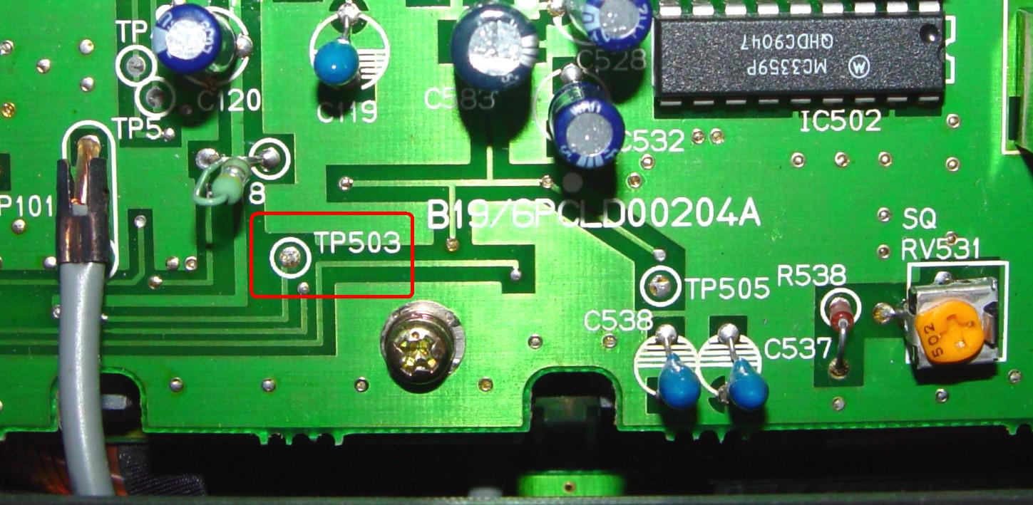
This one was a bit harder but I found TP503 on the RF board near the control head had unsquelched flat (not de-emphasized) receive audio. There is +7.4VDC present here, so you will need to use a coupling capacitor of 10 uF at 16V (or larger) between this point and your repeater controller. The level is approximately 145 mV per 1 kHz of deviation. This signal feeds the volume control circuitry.
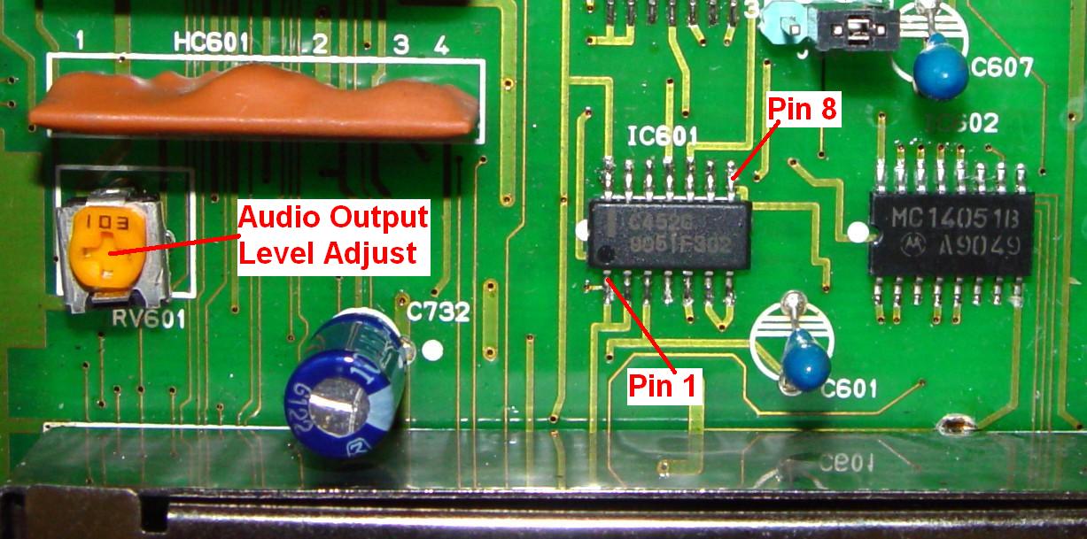
You can get it at IC601 pin #1 on the command board as well.
A similar signal but at a level governed by RV601 (Audio Output Level Adjust) on the command board, is also available. It is flat (not de-emphasized), has had analog and digital Channel Guard signals filtered out, and IS squelched or muted. It is available on IC601 pin #8 on the command board.
Most repeater controllers can deal with flat audio and they have a de-emphasis circuit built in. They probably will work better with squelched or muted audio, but some will use the COR signal to mute the audio path internally. Check the controller's documentation.
Unfortunately the MLS-II radio's receive audio doesn't get de-emphasized until after the volume control, when it hits the loudspeaker's audio amplifier. While you can get it there, its level will be affected by the front panel volume control, which is not at all desirable for repeater use.
COR Output:
I found two places that had nice COR (Carrier-Operated Relay) signals, both on IC705 under the shield on the command board. Pin #10 (also called COS, or Carrier-Operated Switch)) or the feedthru hole it goes to, has +5V when no signal is present, or 0V when a signal is present. This only reacts to the presence of carrier; it ignores any analog or digital Channel Guard that may or may not be there. The front panel BUSY LED follows this signal.
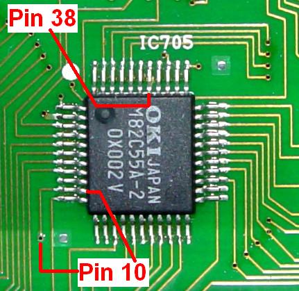
A better point is on pin #38 (called RX MUTE). This has +5V when no signal is present, or 0V when a signal with the correct analog or digital Channel Guard is present on the carrier, or if you press the front panel MONITOR button to unsquelch the radio.
You should use some sort of buffer on either of these pins. Don't connect either one directly to your repeater controller unless you know for sure that it won't load anything down.
Ground:
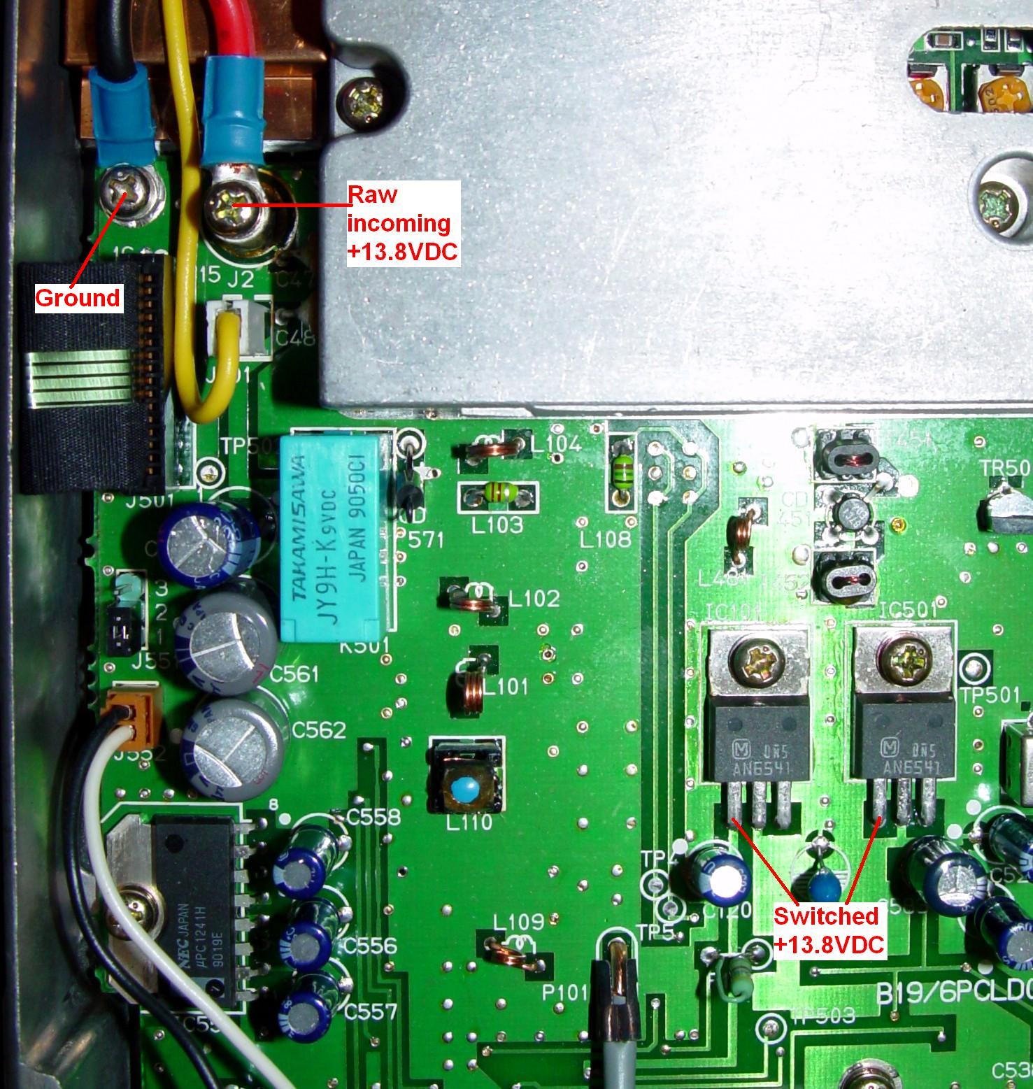
Ground can be obtained from the black incoming power wire screw terminal or from the microphone connector pin #5.
Other Notes:
You can force the radio to always come up running (turned on) by adding a wire from the incoming +13.8VDC screw terminal to the left lead of either IC501 or IC505. Normally the power relay feeds these regulators when you turn the radio on; the wire just bypasses the relay's contacts.
You should program the radio for just one channel. That way, if the repeater should lose power, it will come back on the one and only channel that's programmed into it.
Let the transmitting radio encode analog or digital Channel Guard, as it will handle Squelch Tail Elimination (STE) according to the programming data.
If you use the flat, unfiltered receive audio source, your repeater controller could decode analog or digital Channel Guard itself rather than the receiver doing it. I prefer to let the radio handle both the encoding and decoding chores.
The radio defaults to requiring analog or digital Channel Guard signalling present on signals whose channels that have it programmed. If you want to place the receiver into carrier-squelch mode, you can ground the microphone connector pin #7 (CG DSBL/TXD). This can be connected to an auxiliary output from your repeater controller.
Acknowledgements and Credits:
Channel Guard, CG, and DCG are trademarks of Harris / MA/COM / GE / Ericsson, Inc, or whatever they're called these days.
Schematic information came from the relevant LBIs on repeater-builder.
Contact Information:
The author can be contacted at: his-callsign [ at ] comcast [ dot ] net.
Back to the top of the page
Up one level (GE index)
Back to Home
This article created Friday 19-Sep-2014.
Photographs, article text, and hand-coded HTML © Copyright 2014 by Robert W. Meister WA1MIK. All photographs were taken by the author unless otherwise indicated.
This web page, this web site, the information presented in and on its pages and in these modifications and conversions is © Copyrighted 1995 and (date of last update) by Kevin Custer W3KKC and multiple originating authors. All Rights Reserved, including that of paper and web publication elsewhere.