Back to Home
Modification
By Doug Crompton WA3DSP

|
Up one level Back to Home |
GE MVP PA 5 Watt Modification By Doug Crompton WA3DSP |
|
This article tells how to convert a 20 or 35 watt MVP UHF PA board to 5 watts. We use the MVPs strictly for link transmitters at remote sites for our repeater. 5 watts with a small beam is more than adequate for the link. They have been in operation for years and are generally very reliable. The original designer of the system cut the case open above the final board and installed a muffin fan blowing on the board. The final spring mounted cover is left off.
The coaxial output lead was removed from its original position at the output of Q203 (20w PA) or Q204 (35w PA). The shield is soldered to a screw lug and was originally under the bottom screw second from the left, the one showing just below the green tape. This lead and lug were moved to the top right screw in the photo.
Locate C19, a 680 pF capacitor that couples Q202 to Q203. Lift the lead on the Q203 end. As you can see in the photo below, I just let it hang and soldered the center conductor of the coax output cable to it.
There is also a 3 pF capacitor that is shown in the official 5 watt schematic going to ground from this junction. I experimented with this and found that there was no real difference with or without it. It exists on the board but in order to use it you would have to remove other components. If you think it is necessary then add a new one from the 680 pF and center conductor connection to ground. Here is a photo of the modified PA board (click on it for a larger view):
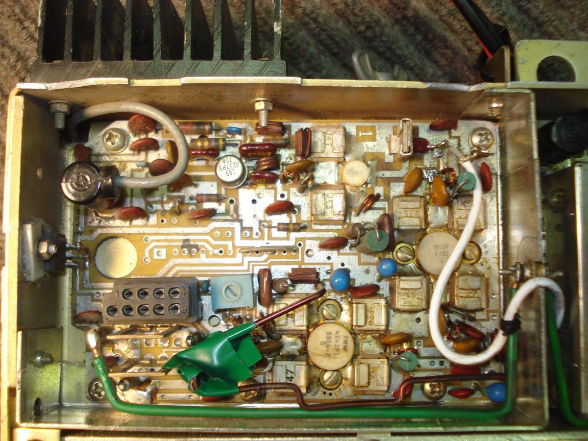
In the photo you can see some ugly green tape around the power leads to the two final transistors that were bypassed. I unsoldered the source end at the two current shunts below the test connector and put tape over them. This is not absolutely necessary but I figured it was good practice to not leave the power on the unused devices.
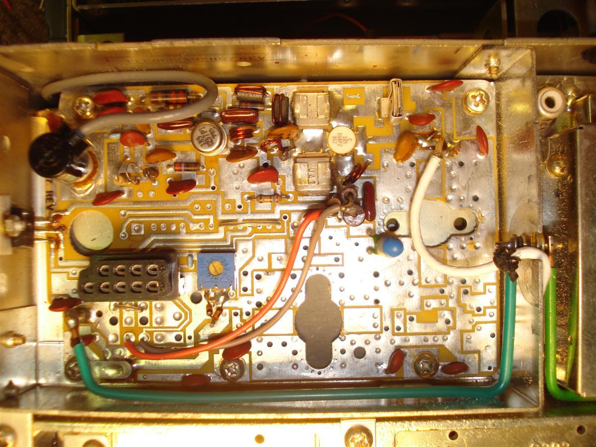
If you look at the stock 5-watt final photo you can see that they put a current shunt resistor with two wires over to the test connector. I chose not to do this to make it easier to return the board to its original state. For comparison, here's a photo of a stock 5-watt PA board (click on it for a larger view):
During on-air testing (key down for extended periods into a dummy load), I found that Q202 stays very cool. In fact there is no perceivable temperature increase around the device. On the other hand, Q1 (AMPL 1) can get quite hot. This device has no heat sinking. I was successful in lowering the dissipation by reducing the collector voltage. There is a 22 ohm resistor supplying power to Q1 and I ended up putting in two more 22 ohm resistors in series which lowered the collector voltage to about 7 volts. This resulted in just a very slight decrease in output power and a greatly reduced case temperature.
The following are possible replacements for Q1 and Q202:
The following LBIs cover the MVP UHF PAs. Refer to these for schematic diagrams and component locations.
The author can be contacted at: doug [ at ] crompton [ dot ] com.
Back to the top of the page
Up one level
Back to Home
Article and photos Copyright © 2012 by Doug Crompton WA3DSP.
Hand-coded HTML by Robert W. Meister WA1MIK.
This web page, this web site, the information presented in and on its pages and in these modifications and conversions is © Copyrighted 1995 and date of last update by Kevin Custer W3KKC and multiple originating authors. All Rights Reserved, including that of paper and web publication elsewhere.