Back to Home
(usually called the "Z-Matcher")

|
Up one level Back to Home |
An Overview of the GE MASTR II Transmitter Output Stage
Impedance Matching Unit (usually called the "Z-Matcher") |
|
From an email to repeater-builder:
The Z-Matchers were not included with GE repeaters until they documented that they had a problem with Hi-Q reactive loads (e.g.: Duplexers). This did not happen until about 1978. At first the Z-Matchers were supplied by Decibel Products and later GE put their own Z-Matcher on the filter board in place of the antenna relay. This did not solve all of the problems with the broad band PA's. There were still PA's failing that high-Q reactive loads, but at a much lower rate; especially on UHF. You should remember that a duplexer presents a 50 ohm load only at the tuned frequency; all other frequencies it presents a reactive load to the PA. A Z-Matcher with a ferrite isolator / circulator between the PA and the duplexer solved most all of the PA failure problems. This was to expensive to make it a standard on GE PA's, so the Z-Matcher was the only advertised solution.
P.S. the fans on PA's were always an option to be purchased by the users when needed.
Fred W5VAY (Retired GE Engineer)
The above explains why the impedance matching option is found only in the later GE transmitters and the associated LBIs (both VHF and UHF). The scans below came from a UHF book, LBI-30201. This LBI can be downloaded as a PDF from the LBI page at this web site.
EMR Corporation makes external Z-Matchers for both VHF and UHF. Photos of an EMR UHF unit are at the end of this writeup.
This article apparently came from http://w4zt.com/zmatch/.
The GE documentation gives the following tuning instructions:
| Antenna Matching Unit Adjustment |
The Antenna Matching Unit is used only in continuous duty duplex stations
to optimize impedance matching between the power amplifier and the load.
It consists of a Pi network (C2-C5 and L1) and a reverse directional
coupler. RF from the low pass filter is applied to the Pi network through
the reverse directional coupler and then to the duplexer load. The
reverse directional coupler permits monitoring the reflected power.
Note: The residual voltage reading after tuning may vary from one transmitter to the next depending on the output power level, operating frequency, and load. |
A better way is to add a DC ammeter in line with the PA deck and tune for best efficiency AS WELL AS the minimum reflected power.
| (click the small pictures to see a larger picture in a new browser window) | |
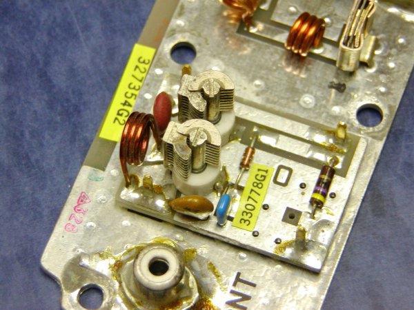 VHF Z-Matcher |
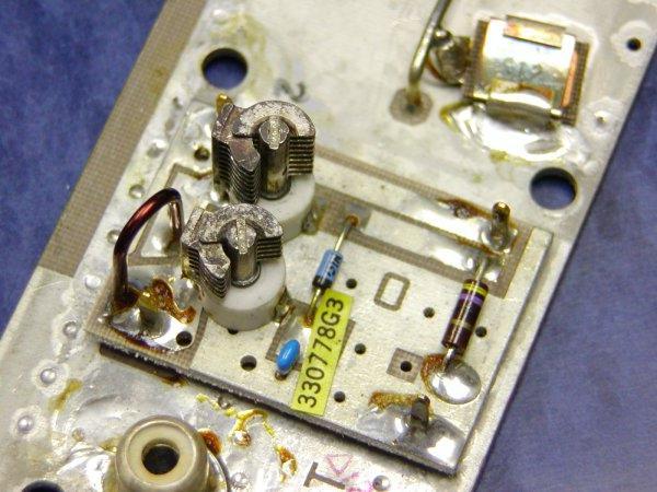 UHF Z-Matcher |
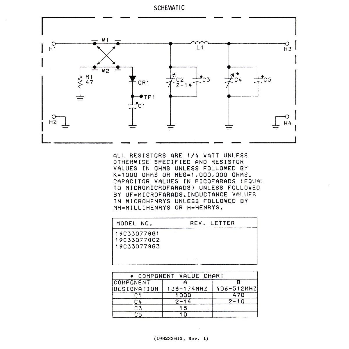 Z-Matcher Schematic (the table at the bottom has information for both high band and UHF). |
|
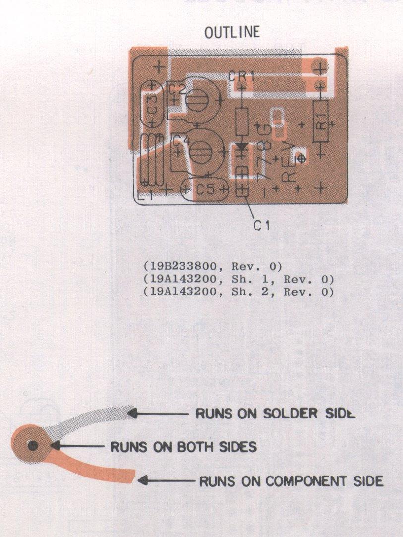 Z-Matcher Board layout |
|
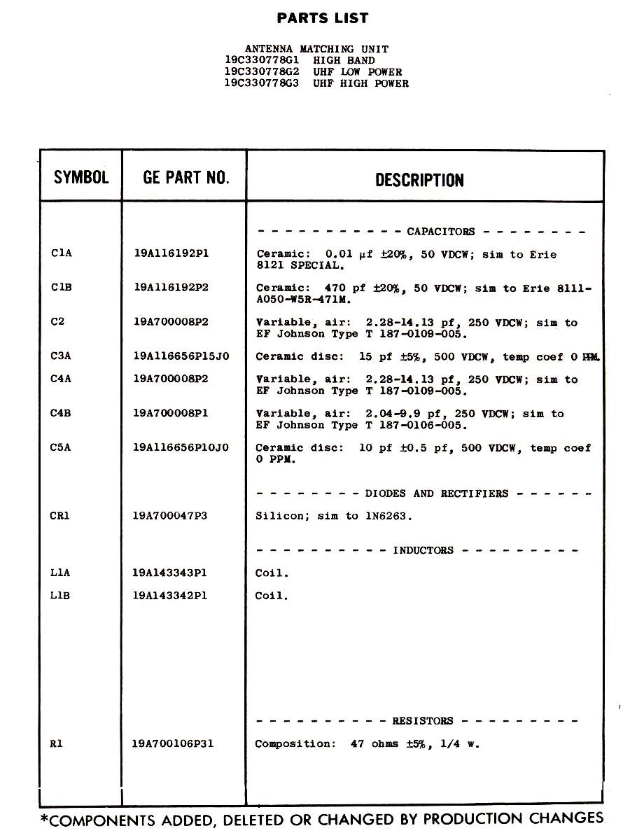 Z-Matcher parts list |
|
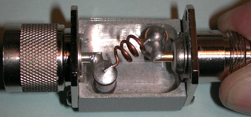
As mentioned above EMR Corp sells external matching units. Here are two photos of a UHF one.
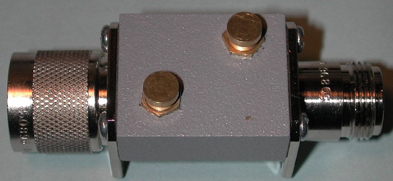
The little round brass caps unscrew to expose the piston trimmer adjustments.
DB Products also made Z-matchers. Here's their tuning info writeup:
DB Products Z-Matcher Tuning Information
Back to the top of the page
Up one level
Back to Home
This page first posted 17-Oct-2008.
This web page, this web site, the information presented in and on its pages and in these modifications and conversions is © Copyrighted 1995 and (date of last update) by Kevin Custer W3KKC and multiple originating authors. All Rights Reserved, including that of paper and web publication elsewhere.