Home page
C300C30R VHF Amplifier
for 6 meter Operation
By John Haserick W1GPO

|
Up one level Home page |
Modifying the Henry C300C30R VHF Amplifier for 6 meter Operation By John Haserick W1GPO |
|
Background:
This is a continuous duty, 30-40 watt input, 300 watt output, FM low-band amplifier. Originally on 43-46 MHz, it was picked up at a flea market and donated to our repeater group. Typically these amps cover a 5 MHz portion of the 30-60 MHz band. They can be purchased already tuned for 6 meter operation. There are apparently several models or vintages of the C300C30R and they are also available with input power levels of 10 or 3 watts. You can find a manual for this amplifier on the Henry Radio page on this web site.
Click on any photo for a larger view.
Modifications:
The three coil harmonic filter (along the lower left) was readjusted slightly using a spectrum analyzer with tracking generator and a return loss bridge. The coax was disconnected at the transmitter circuit board and fed to the test equipment. It ended up with the coils spread out a little, as shown in the photo below.
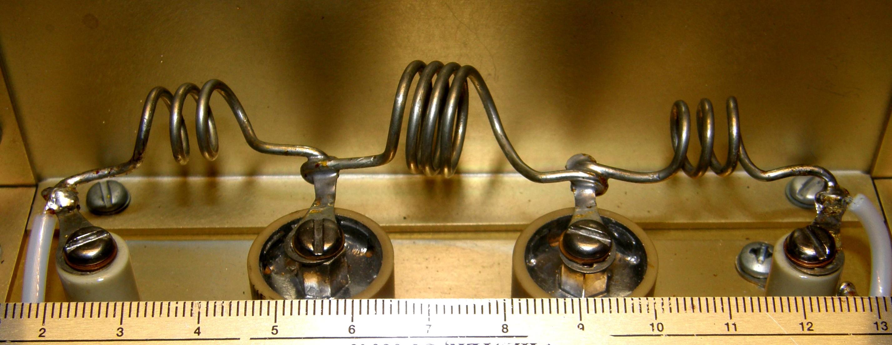
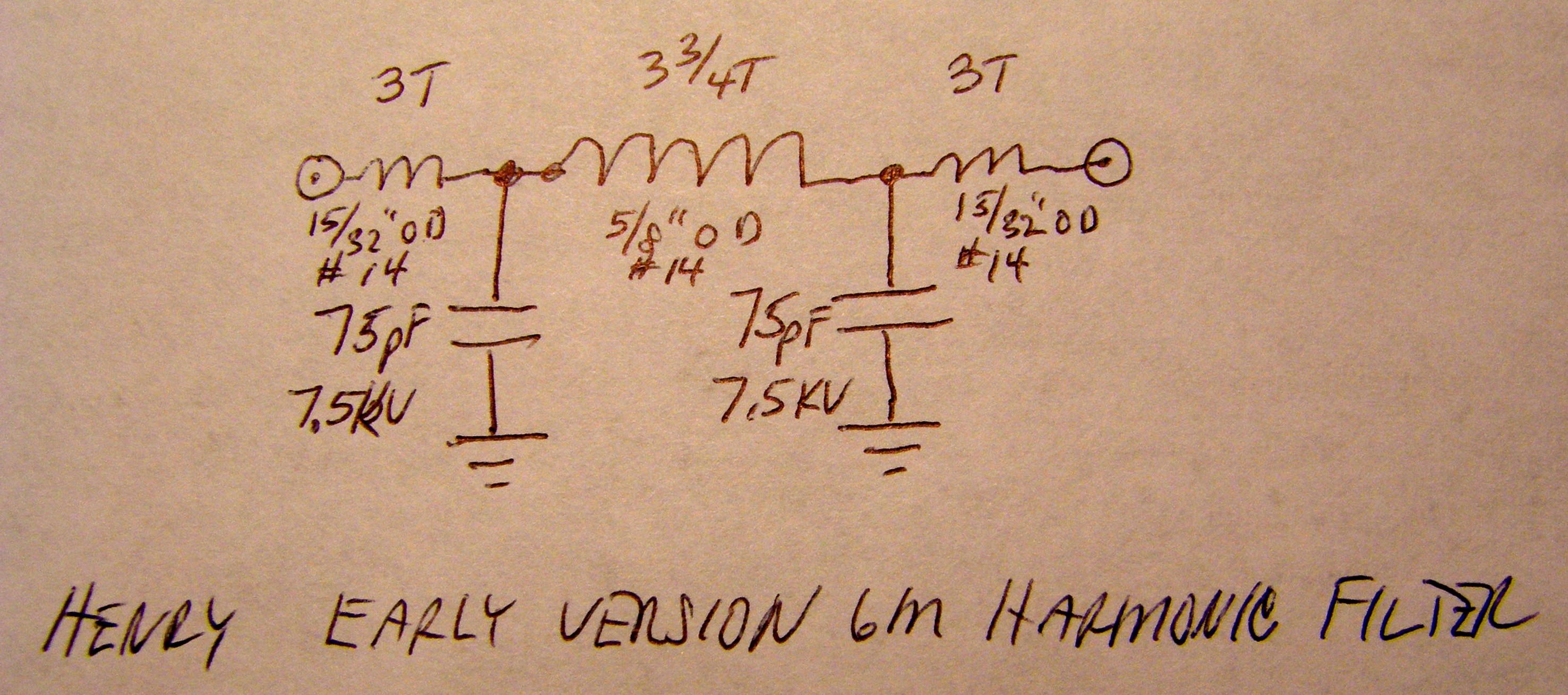
For completeness, here's the schematic of the harmonic filter.
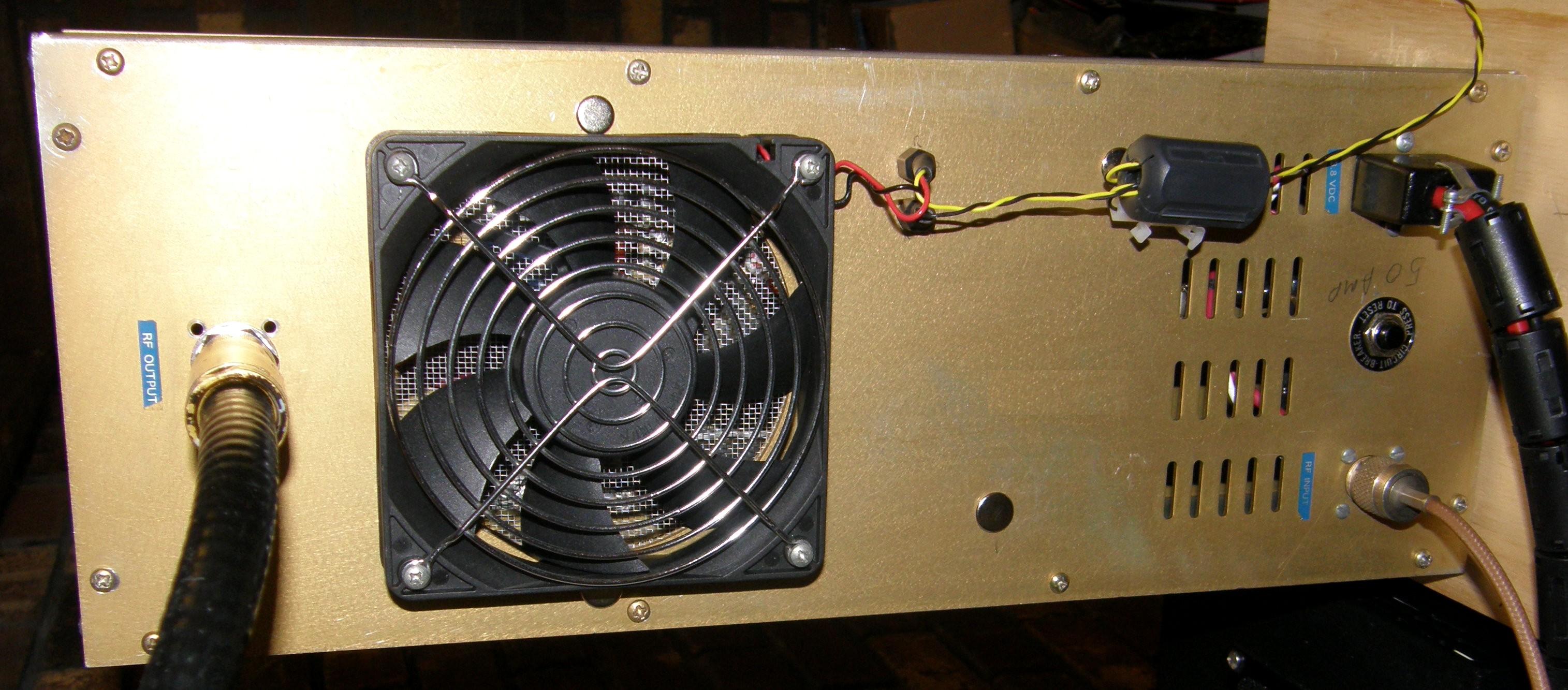
The UHF-female output connector was replaced with an N-female connector. Originally the RG-400 output coax was a lot longer so the output connector did not have to be removed from the panel, as it is in the photo below.
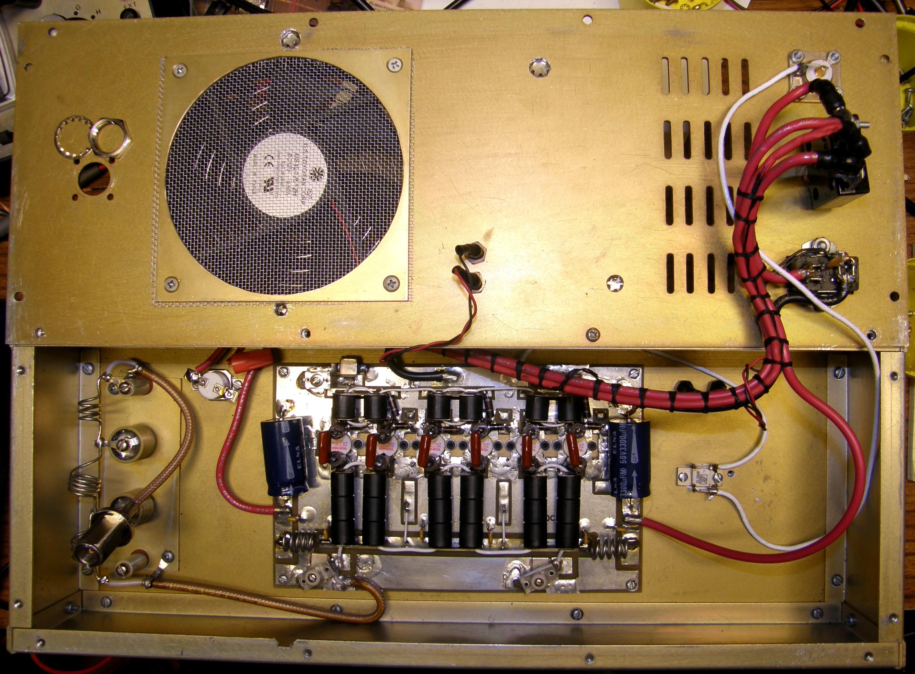
The fan circuit was disconnected from the internal thermostat (mounted on the heat sink) and connected to the PTT line via a relay with a 20 second delayed turn-off, because the big 2-watt carbon resistors were getting too hot before the heat sink warmed up enough to turn the fans on, and then the very loud fans would take forever to turn off at 78 degrees ambient room temperature.
Our amp came with two adjustable compression trimmer capacitors for tuning the input circuit, visible in the photo above along the top edge of the circuit board. Two 3/8-inch holes were drilled in the top cover so the compression trimmers could be adjusted with an insulated tuning tool with the cover on (the cover needs to be on when transmitting to avoid excessive RF exposure to the operator). Snap-in plugs were used to seal the holes after tuning.
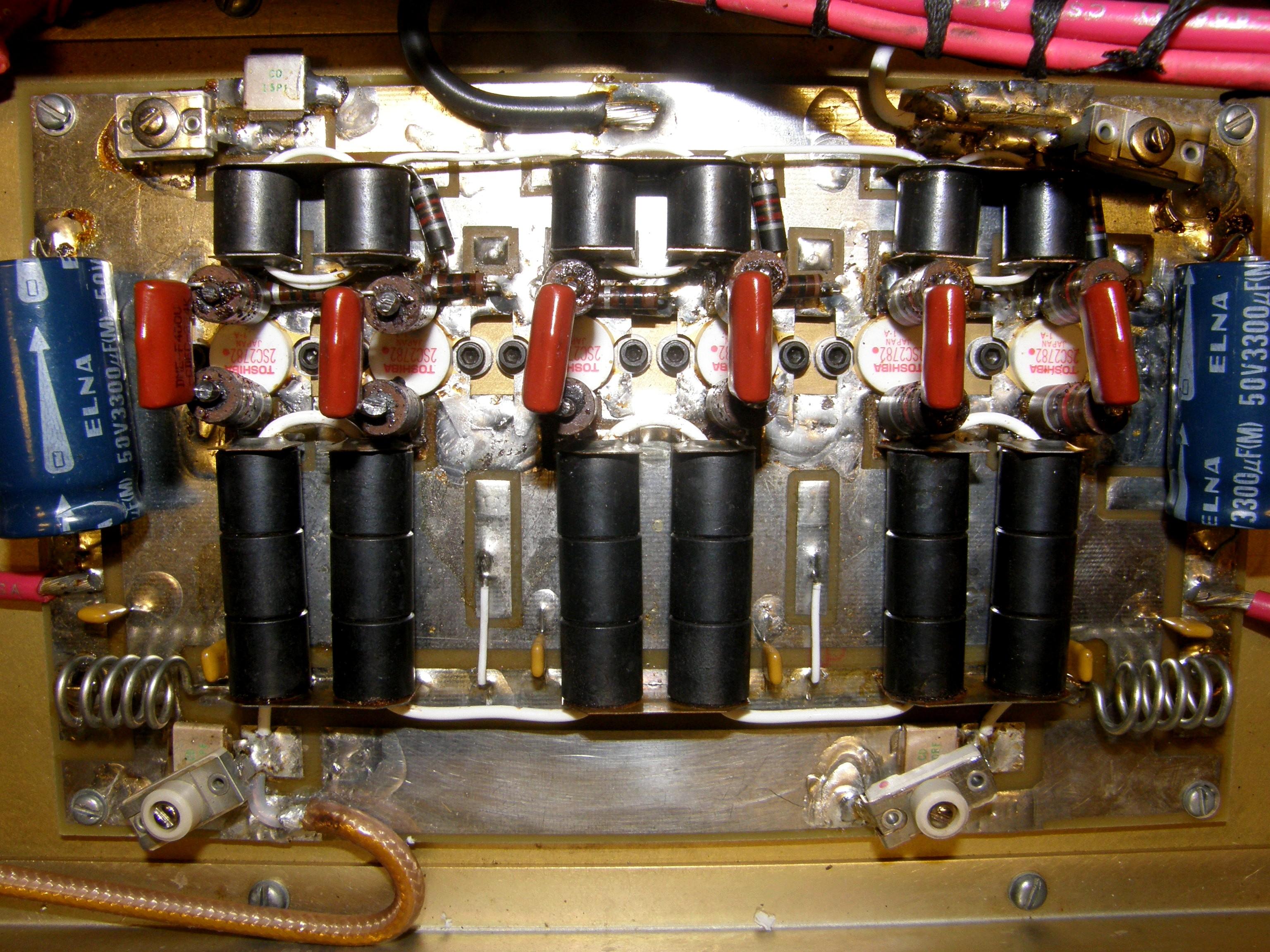
Our amp lacked any adjustable output tuning components. Both the hot and cold side of the output circuit had two parallel-stacked metal-cased transmitting mica caps. The top ones were 50pF, while the hot side bottom one was 120pF and the cold side bottom one was 110pF. All four caps were removed then the two 50pF caps were soldered back to the board and some 8-80pF (approximately) compression mica trimmer caps were then soldered over the top of the 50pF caps. Two more 3/8-inch holes were drilled in the cover for adjustments. It appears that two mica caps were required in parallel to handle the high transmit currents. It likewise seems that it is best they are close to the same value, to help divide up the load current. About 90-100pf of total capacitance on each side of the output is required to tune the amp on 6 meters without the need of a Z-match.
Update November 2020: The larger size of these variable caps did not introduce amplifier instability. The two mica compression caps on the output of the older version Henry amp with the three coil harmonic filter were replaced with 3-55 pF 750V PC mount low inductance air variables from Surplus Sales of Nebraska (part number CTA-194-18-5). The fixed metal clad mica on the output coax side was changed to a 100 pF 500V, and the fixed metal clad mica on the other side was replaced with a 75 pF, but the original 50 pF would have been a better choice as the air variable ended up after tune up more than 3/4 open with the 75 pF fixed mica (see photo below before tune up). The output efficiency increased about 10% over the compression micas. The output was stable, clean, and the air variables were easy to peak without being too touchy. The rotor of the caps was connected to ground. Several other air variables we looked at had narrower terminals that may not take the current of these low inductance air variables.
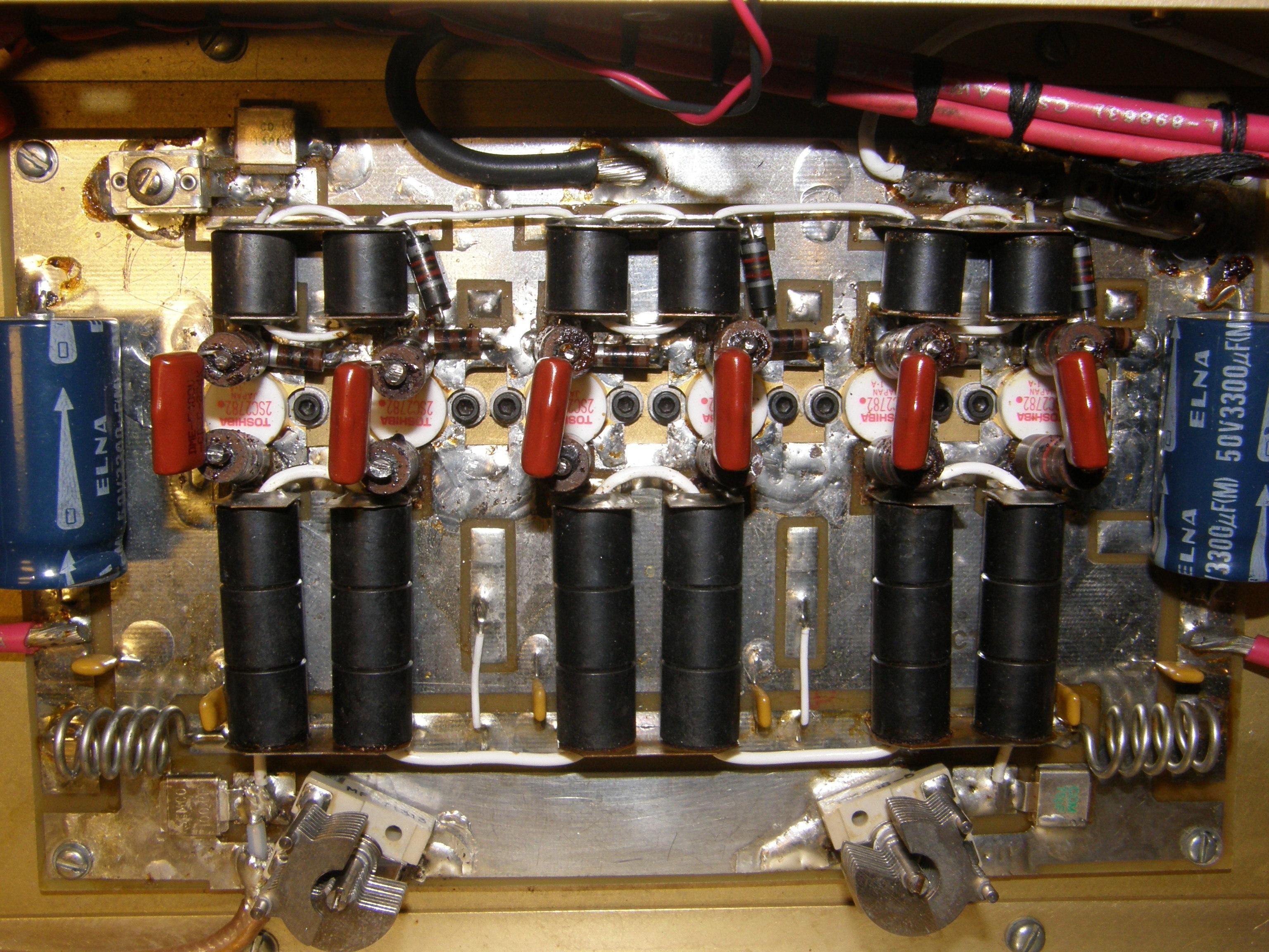
By the way, the black cylindrical objects along the bottom of the circuit board are three ferrite output transformers, with the secondaries series-wound with a length of white Teflon wire.
Final Results:
The photo below shows the outside of the amp when in service. You can see some of the hole plugs around the fan, in the area of the tuning capacitors. The other side has a finned heat sink and two more 4-3/4 brushless ball-bearing 12VDC inch fans.
With 30 watts of input power, we ended up with nearly 300 watts out, drawing 35A at 14.0V, from an Astron SS-50A switching power supply that should be good for 40A continuous. For some reason the unit we have seems to overheat above 32-33A and shuts down even at 66 degrees ambient temperature!
Even Better Results:
As it appeared that the diameter of the white secondary winding was thinner than optimum, this original #16 Teflon coated silver plated stranded wire was replaced with the green #12 silver-Teflon wire of the close to the same length (maybe 3/8 inch longer because the turns were not quite as tight). Results were that the metal clad mica on the right side had to be increased from 75pF to 100pF, so now both micas were 100pF and now both variable caps were closer to the same opening. See the photo below.
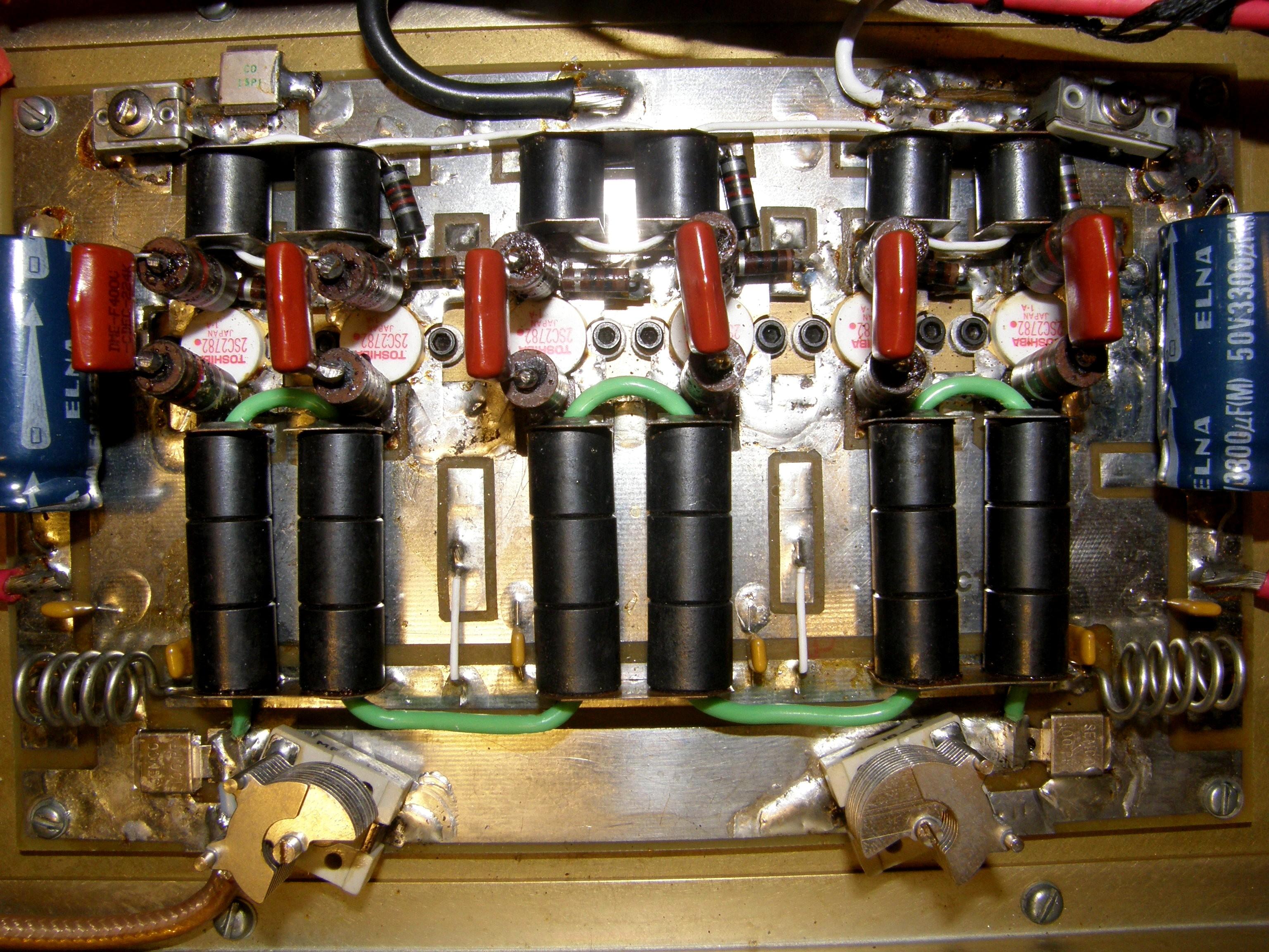
Also, there was a definite increase in output with the same input power to the amp, almost as if the original design used a heavier gauge wire and was more optimal. The original design may have used a tuned output on one side of the secondary, and then the design was changed to all metal clad fixed micas in the output secondary circuitry, which required a lower Q, to create broader tuning. There was no increase in spurious or repeater desense with the change. EBAY is a good source for the wire.
By the way: Teflon can undergo what they call "cold creep," so the restrung #12 wire should not be pulled so tight that there is no play at all or the Teflon coating can undergo cold creep at any sharp corners, creating a short to the ferrite transformer. That would be a very bad thing.
Contact Information:
The author can be contacted at: jhaserick84 [ at ] comcast [ dot ] net.
Back to the top of the page
Back to Henry Radio Index page
Back to Home
This article created on Wednesday 08-May-2019
Article text and photographs © Copyright 2019 by John Haserick W1GPO.
Conversion to HTML © Copyright 2019 by Robert W. Meister WA1MIK.
This web page, this web site, the information presented in and on its pages and in these modifications and conversions is © Copyrighted 1995 and (date of last update) by Kevin Custer W3KKC and multiple originating authors. All Rights Reserved, including that of paper and web publication elsewhere.