Back to Home
TK-6110 35-50 MHz
Mobile Radio to 6-Meters
Radio Conversion by John Haserick W1GPO
Programming Info by Roger Coulson WA1NVC
Converted to an article by Robert W. Meister WA1MIK (SK) Maintained by Mike Morris WA6ILQ

|
Up one level Back to Home |
Converting the Kenwood TK-6110 35-50 MHz Mobile Radio to 6-Meters Radio Conversion by John Haserick W1GPO Programming Info by Roger Coulson WA1NVC Converted to an article by Robert W. Meister WA1MIK (SK) Maintained by Mike Morris WA6ILQ |
|
Background:
The TK-6110 features 70W power, 8-character alphanumeric display, front speaker and
compact dash mount chassis. The noise blanker function reduces sensitivity to vehicle
ignition noise common with low-band frequency radio equipment. The accessory connector
interfaces to headset/intercom systems, headset/PTT systems, or remote control panels for
base/control station fixed installations. Additional features include 29.7-37.0 MHz or
35.0-50.0 MHz, 32-Channels, 7 Programmable Function Keys, Die-Cast Chassis, Priority Scan,
Mil-Std 810 C, D and E, Operator Selectable Tone/Code (OST). Unavailable Frequencies:
TK-6110K (29.7-37.0 MHz model): 33.60 MHz, TK-6110K2 (35.0-50.0 MHz model): 42.00 MHz.
The TK-6110 was discontinued in October of 2018
These radios come in two band-splits: one covers 29.7-37 MHz, the other covers 35-50 MHz. Make sure you've got the higher band-split model; there must be the "K2" after the model number on the radio's sticker. The "K" model would be suitable for 10-meters right out of the box. One of he outstanding features that sets the TK-6110 apart from many amateur 6-meter FM radios is the rapid PL decode time and reverse burst recognition, so there's no loss of initial speech and no squelch noise burst at the end of received compatible transmissions.
The Kenwood TK-6110 comes in two versions: the original/older one and the newer one with serial number A8B00001 and higher.
There are basically two ways to convert the radio to 6-meters: the complex way and the easy way. The complex way is to follow the alignment procedure in the service manual, which requires a lot of test equipment and time. This article will do it the easy way. The conversion consists of modifications to the transmitter Power Amplifier (PA) and the receiver front end.
Click on any photo or image for a larger view.
Transmitter Modifications:
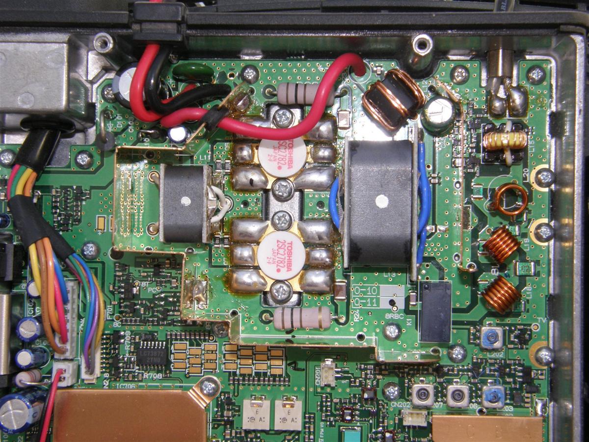
After first checking performance on the original low band frequency, program the radio with some 6-meter frequencies, spread the harmonic filter coil (L18) closest to the RX cans about as shown, and tilt the vertical coil (L20) next to the SWR sensing coil (L16), slightly more away from that coil, for lowest DC power current with the most output power on the highest TX frequency (only for the original version - the newer version probably doesn't need to be changed). The photo below shows the coils as they are originally.
The photo below shows the coils as they are after being adjusted.
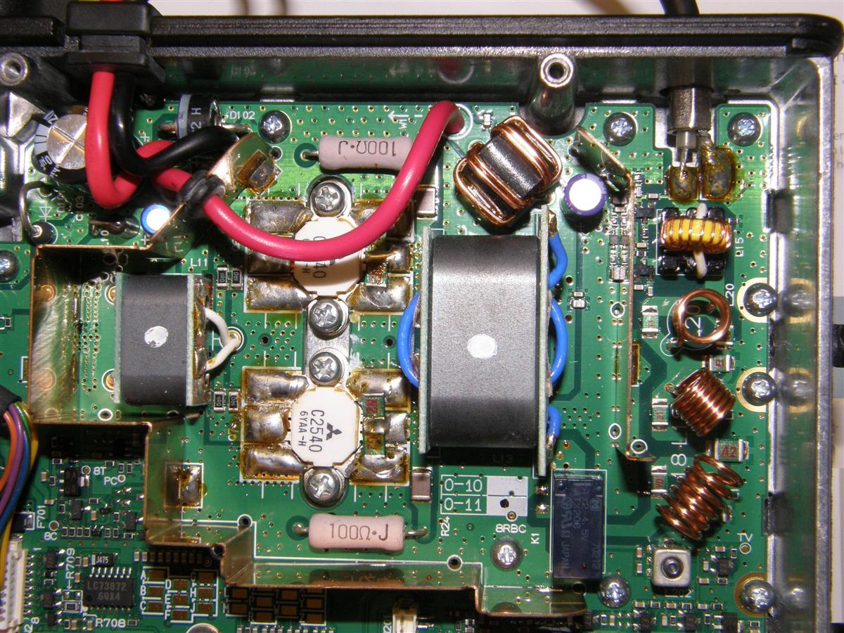
The photo with the spread coil is a converted original version. The photo of the new version has also been converted to 6-meters, but the harmonic filter coils did not need to be fooled with. We noticed that the original version's vertical coil (L20) was not tilted away from the SWR sensing coil (L15), but the newer version's unmodified harmonic filter vertical coil was. So we went back and played around tilting it farther away, with no difference in current draw or output, so we should probably say to leave the vertical coil (L20) alone.
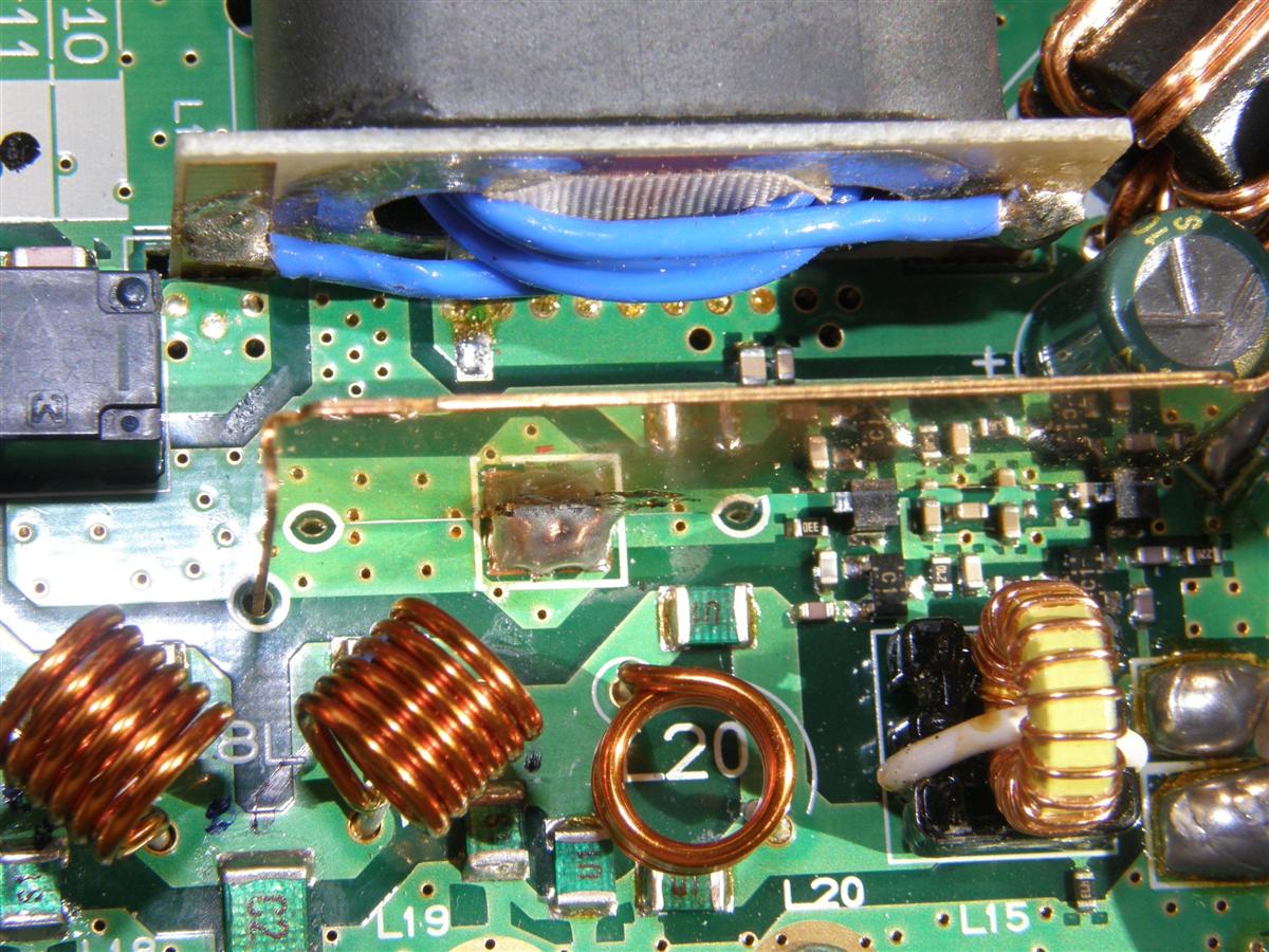
There was a length of blue Teflon insulated wire that forms the secondary winding of the PA output transformer (L13). To increase the efficiency on the original version PA, that wire was unsoldered, removed, shortened by 1-1/4 inches, and rewound so that the wire enters and leaves the holes nearest where they are soldered, rather than going through the far holes as originally done. On the newer version PA, shortening that wire by rewinding it made the efficiency WORSE, (probably because of less output capacitance on the newer version), so everything on the newer version PA should be left alone for 6-meters. You can see this difference in the two pictures below. The first photo shows the original blue wire winding whose ends cross over each other.
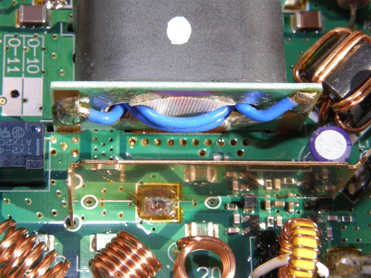
This photo shows the rewound blue wire whose ends do NOT cross over each other.
A portion of the PA schematic is shown below.

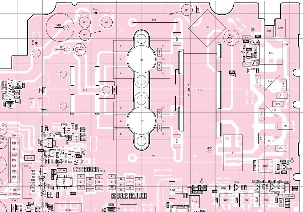
A portion of the circuit board X-ray view is shown below.
Receiver Modifications:
Set the RX to 52.75 MHz, set all three sensitivities (using the programming software) to 255, and unscrew and adjust the four front-end slugs (L202, L203, L206, L207) for best sensitivity on 52.75 (assuming the radio is to be used on receive between 51.5 and 53.99 MHz. The IF coils should not be touched without a tracking generator/spectrum analyzer, and the quadrature coil only adjusted for lowest distortion if a distortion meter available. There is some Permlastic Ultra Blue RTV anchoring two of the RX slugs. You can see the four front-end slugs after being adjusted in the lower right corner of the photo below.
We found it best to set all three (low, medium, and high) sensitivity settings to the maximum 255. This eliminates varactor tracking of the four front-end coils, which optimizes performance for 6-meters but willreduce the sensitivity below 50 MHz. The tuning slugs do not have to be positioned almost falling out this way, and sensitivity at the 51.5 and 54 MHz edges is down less than 1 dB from the center tuning peak at 52.75 MHz. We tried the various settings explained in an article to get the radio to do both 10 and 6 meters, but could not get the tracking to completely follow between 51.5 and 54 MHz, and there was actually MORE than 1 dB loss at 51.5 and 54 MHz.
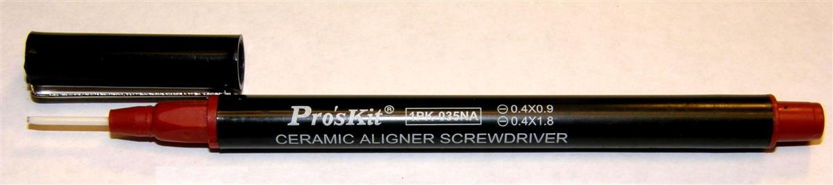
To tune the radio properly, the service manual calls for a spectrum analyzer / tracking generator (SA/TG) to be used for the IF tuning and preferably for the RF front-end tuning, but the receiver could be programmed for 52.75, and the four slugs tuned for best quieting at 52.75. Also it is much easier to tune the slugs with an insulated tool, but that has to be custom made. We used an Eclipse 2-in-1 Ceramic Driver Model 902-191 (0.4x0.9mm tip ground down even further using a fine grit on a belt sander) made by Eclipse Tools and purchased from Cables and Connectors in Newington, CT.
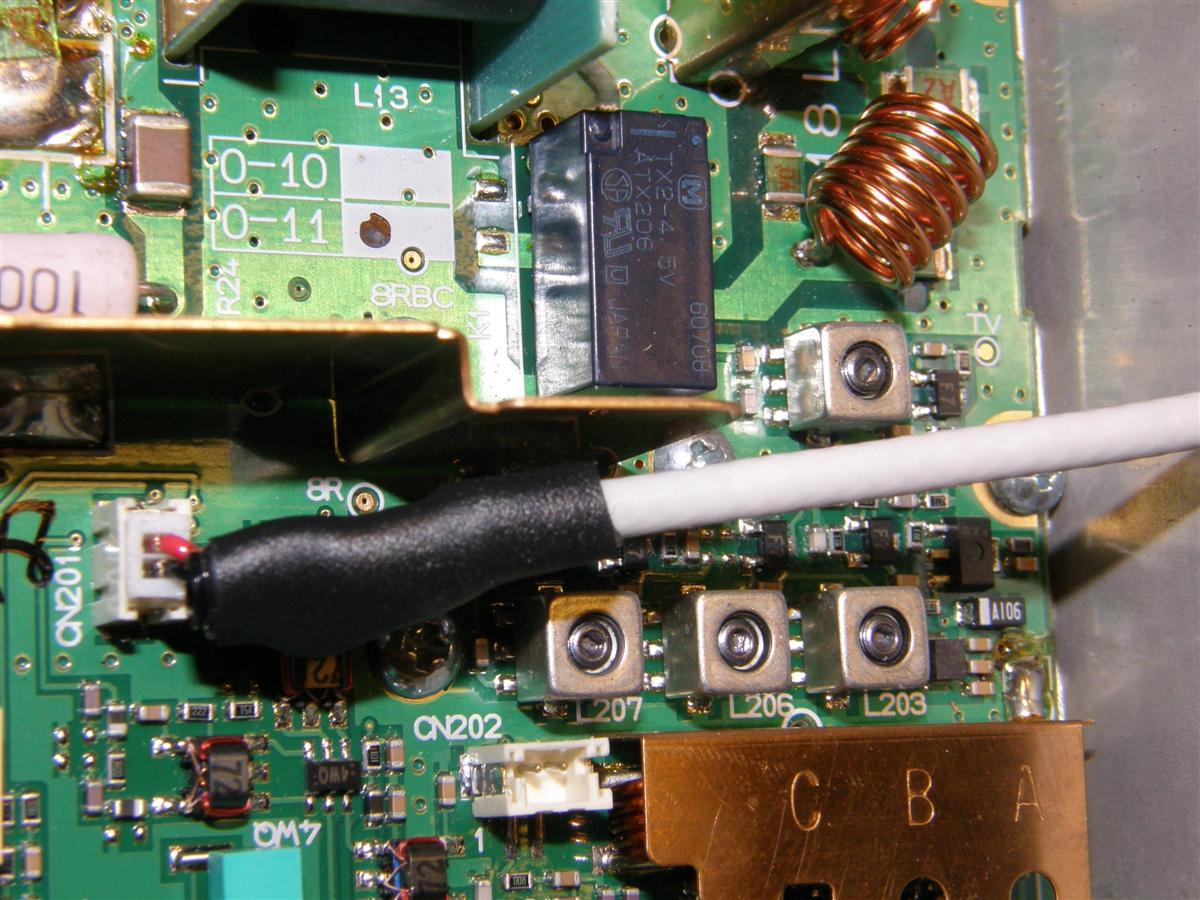
Also required is a pair of 1.25 mm female connectors connected to the SA/TG coax to plug into the radio metering points. Note that the double female 1.25 mm cables from Cables and Connectors have the red and black switched, so we bought two pair and just used one end off each. One is plugged into CN201 in this photo. Also you can see the final/realigned position (height) of the four front-end coils.
The four front-end coil (L202, L203, L206, and L207) slugs CAN easily be cracked if they are turned in to where they stop, which is almost the same tuning as one thread showing out (yes, we broke one) so just turn them slowly OUT usually just to where one thread shows, and probably no RTV needed, at least on the original version radio with all three sensitivities set to 255. The alignment points, test connectors, and front-end coils are identified in the image below.

The alignment with the SA/TG may result in a little better 12 dB SINAD sensitivity because most of the IF adjustments with it did improve the shape of the IF response, but a lot depends on the two 455 kHz ceramic filter response curves over which there is no control. Alignment of the four RF coils using quieting should come close to that achieved by the SA/TG, however. The radio should do close to 0.25 µV for 12 dB SINAD on 6 meters, and about the same for 20 dB quieting. With 13.8V from the power source, current draw for 70 W out should be equal to or less than 12 A, or less than 9A for 50W out. The radio should do 50W amateur duty service with no problems.
Important Update to the Tuning Procedure (February 2020):
I was converting a 35-50 MHz TK6110 for a friend today. It has been a couple of years since working on one of these radios, so I went to this article for a refresher. This time I put a variable attenuator on the HP8920C tracking generator connected to the antenna input, with the SA input on the first mixer test point CN201 and set it for minimum signal without noise on the trace at 30 MHz sweep centered at 52.49 MHz.
With the unconverted receiver, the varactors did a fair job of tracking 39-50 MHz channels, but stopped tracking above 50 MHz, probably resetting to the low end of the range, because the receiver was not supposed to go above 50 MHz. When you put the radio in test mode, the low, middle, and high alignment frequencies are between 35-50 MHz, so you can't align 6M while in test mode. You have to set the low, middle, and high tuning values in test mode, and get out of test mode look at the tracking results, and go back and forth until everything is peaked at each receive frequency. After an hour or so we came up with much better values for 39-54 MHz tracking without loss of sensitivity.
First, all four front end RF coil slugs L202, L203, L206, and L207, need to be unscrewed counter-clockwise until they almost fall out, then glued in place. We used a dab of Permaseal Ultra blue (of course).
Previously, the low, middle, and high tuning values were all set to their maximum value of 255. Of course there is no tracking this way, but the radio has very good sensitivity on 6M. I noticed today there was not as much of a selectivity peak on the received channels as before the conversion, but if low was set to 175, middle at 215, and high at 240, now there was more selectivity on 6M and it also tracked just fine down to 39 MHz. In other words, if the original stock values were low: 50, middle: 130, and high: 230, then reset them to low: 175, middle: 215, and high: 240.
I did the change to a second radio with the same results, but these were both the newest version radios. If an older version radio tracks to, say, only 53 MHz and then resets above 53 MHz, I suggest lowering just the high alignment value down one number at a time, until the receiver tracks to 54 MHz.
Radio Programming:
The KPG59D software will not let you enter a frequency above 50.0 MHz, and we could not figure out how to incorporate the 59X software to do it. Fortunately, Roger cloned his TK-6110 into John's, and John cloned the other TK-6110 radios off that. It was, however, easy to change all the other programming parameters, i.e. display names, output power, button assignment, etc. One neat feature is you can program one button to do talk-around, effectively adding more TX channels. One downside of this radio is that the noise blanker can only be toggled on and off through the programming software, not with any button.
Kenwood Software:
Older Kenwood software was DOS-based. The newer software is Windows-based and will run on all versions of Windows including Windows 10. The software used for the Kenwood TK-6110 (mobile) and Kenwood TK-190 (portable) was KPG-59D v3.01. The Programming cable for the TK-6110 is the KPG-46. This cable is also used to program the Kenwood TK-8xx and TK-9xx series radios.
Kenwood software will not allow you to enter out of band frequencies but will not alter out of band frequencies in the data file. You can change everything else but the out of band frequency. You can even copy and cut and paste the channel information to another location.
One way to program out of band frequencies for 6-meters is to enter a frequency 10 MHz lower and with a hex editor change all the 4x.xxx frequencies to 5x.xxx. It is quite quick and easy as they are in a known location and in a single column.
A newer way has become available courtesy of Pete, N2MCI. He wrote a program to change all the 4x.xxx frequencies to 5x.xxx frequencies. The program is called KWLBHEZP.EXE and runs in a DOS window. This program is available here in the TK-690H conversion article.
This second way works the same as the first except you use KWLBHEZP instead of a hex editor.
Bob WA1MIK subsequently managed to modify the KPG-59D software to eliminate the need for any hex-editing or post-processing of the DAT file. His article can be found here in the Kenwood section. We have not tried that yet.
Pete also wrote a similar program called KW900EZP.exe to convert Kenwood TK-981 and TK-481 data files into the 900 MHz ham band. You can read about programming Kenwood 900 MHz radios in the ham band (out of band) at www.kw902.com and look under TK-981.
Other Features:
The Kenwood TK-190 portable and the TK-690H mobile can also be put on 6-meters. See the notes on these radios in the Kenwood section of the Repeater-Builder web site.
The TA (Talk Around) button allows you to transmit on the programmed RX frequency instead of the TX frequency. It does not add any additional channels. Hams would call this simplex on the repeater output frequency.
The OST (Operator Selectable Tone) button allows you to select one of 16 programmable tone pairs for encode/decode.
We changed the "Test Frequency" channels so we would have test channels across the 6-meter band for alignment.
We used the "Embedded Message" field to store our callsigns and the programming date.
Credits and Acknowledgements:
All of the photographs were taken by John Haserick W1GPO and are copyright by him.
The various diagrams were extracted from the Kenwood TK-6110 Service Manual.
The authors would like to thank Bob WA1MIK for turning a bunch of emails into a viable article.
Contact Information:
John can be contacted at: jhaserick84 [ at ] comcast [ dot ] net.
Roger can be contacted at: his-callsign [ at ] arrl [ dot ] net.
Back to the top of the page
Up one level (Kenwood Index)
Back to Home
This page created on 20-Mar-2017 by WA1MIK.
Article text and photos © Copyright 2017 by John Haserick W1GPO.
Article text © Copyright 2017 by Roger Coulson WA1NVC.
Converted to repeater-builder format by Robert Meister WA1MIK (SK).
This web page, this web site, the information presented in and on its pages and in these modifications and conversions is © Copyrighted 1995 and (date of last update) by Kevin Custer W3KKC and multiple originating authors. All Rights Reserved, including that of paper and web publication elsewhere.