Back to Home
TK-690H 40-50 MHz
Mobile Radio to 6-Meters
By Roger Coulson WA1NVC

|
Up one level Back to Home |
Converting the Kenwood TK-690H 40-50 MHz Mobile Radio to 6-Meters By Roger Coulson WA1NVC |
|
Background:
The TK-690H features 100 watts power out, front and remote mount capability, dual band and dual head configurations, basic and full feature control heads, 160 channels capacity, Operator Selectable Tone, noise-canceling microphone, and a wide selection of options.
The TK-690H comes in three overlapping band splits: Type 1, 29.7-37.0 MHz, FCC ID ALH22923110; Type 2, 35.0-43.0 MHz, FCC ID ALH22923120; and Type 3, 40.0-50.0 MHz, FCC ID ALH22923130.
The 29.7-37.0 MHz split radios are suitable for 10-meter operation. The 40.0-50.0 MHz split radios are suitable for conversion to 6-meter operation. The radio band split can be determined by the last two digits of the FCC ID number: 10 for 10 meters and 30 for conversion to 6 meters.
The 10-meter radio conversion requires no hardware modifications. The 6-meter radio required hardware modifications to move the VCOs up in frequency to cover the 6-meter band.
Click on any photo for a larger view.
VCO Modifications:
Obtain a piece of 1/16-inch diameter brass rod and either Electronic grade or non-corrosive RTV.
Test the radio on the original frequency; verify it meets specifications; and save the original programming personality using KPG-44D V2.01 (this is a Windows program).
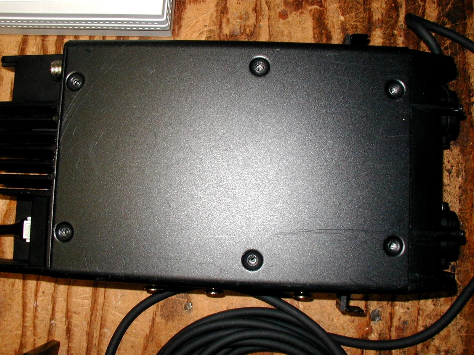
Turn the radio upside down, remove the bottom screws and the cover.
Measure the voltage at test point "CV" (near the center of the board next to the VCO cover); it should vary from 1.5 VDC at 50 MHz to about 7-8 VDC at 40.0 MHz in receive and transmit modes (use test frequencies). See the marked photo below.
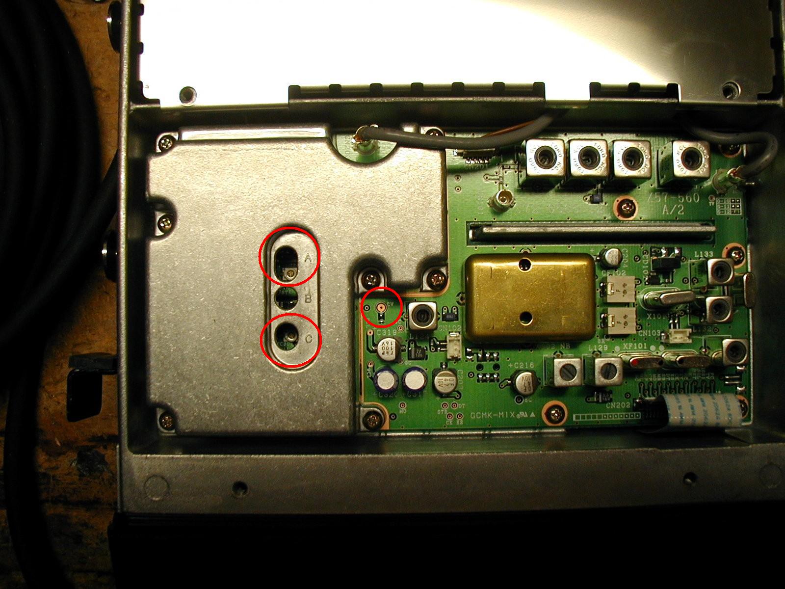
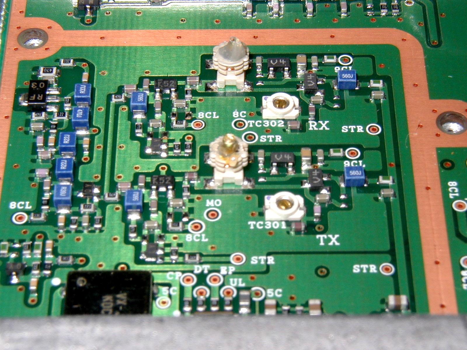
Prepare two brass slugs, each slightly less than 1/4 inch long, from the 1/16-inch brass rod. Remove power from the radio, remove the VCO cover, and re-apply power.
Temporarily insert the brass slug into the RX VCO coil. See the photo below.
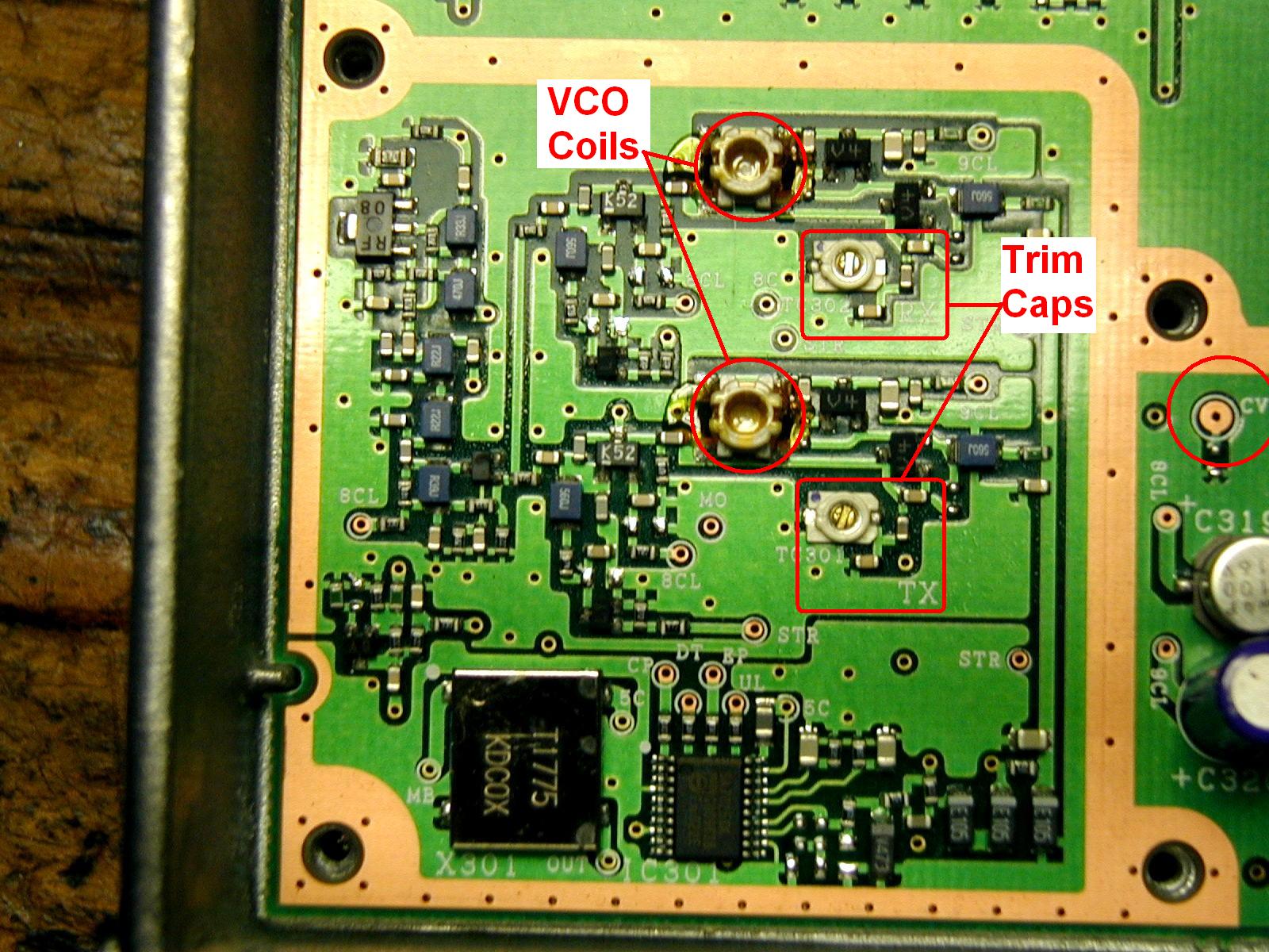
Adjust the RX VCO trim capacitor (labeled "A" on the VCO cover) for a minimum of 1.5 VDC at test point "CV" at the 53.99 MHz test frequency.
Temporarily insert the second brass slug in the TX VCO coil. See the photo above. Adjust the TX VCO trim capacitor (labeled "C" on the VCO cover) for a minimum of 1.5 VDC at test point "CV" at the 53.99 MHz test frequency.
Remove the brass slugs, fill the center of the coils with RTV, and insert the brass slugs into the RTV making sure they are well coated, as the brass slugs will be upside down and must not be microphonic. Use electronic-grade RTV such as Permatex UltraBlack, which is inexpensive and available at every automotive store.
Remove power from the radio, re-install the VCO cover, and re-apply power but DO NOT turn the radio over and do not put the bottom cover back on. The RTV needs about 12 hours to cure.
Check the VCO alignment with the radio still upside down. The voltage at point "CV" should vary from a minimum of 1.5 VDC at 54 MHz to a maximum of 8.0 VDC or less in both RX and TX modes at the lowest frequency, which will now most likely be above 40 MHz but should be OK down to about 45 MHz.
The 6b120607.dat data file is for a front-mount radio with the basic head. The 6f120607.dat data file is for a front-mount radio with the full head. Both files contain the full 6-meter band plan with both 1 MHz and 0.5 MHz pairs.
Harmonic Filter Modifications - Plus Receiver Varactor Retuning:
This information mostly applies to radios produced after serial number 3XXXXXXX. Earlier radio firmware and possibly component differences in the prior production radios will not allow for tracking 40 to 54 MHz, a control head button cannot be programmed to toggle the noise blanker on/off using the modification of output A03, and some of these radios may have the very narrow "F" labeled ceramic filters. All the newer radios have ceramic filters with "E" label that control the IF skirts to a -6 dB modulation bandwidth between +-7.5-8.3 KHz.
The service manual labeled "TK690H (B)" applies to radio serial numbers from 3XXXXXXX to the serial numbers beginning with the letter A or B, for which the service manual labeled "TK690H (B) Revised" applies to serial numbers after that. Refer to the service manual for harmonic filter component locations.
There is a RX side mini low-pass filter that needs modified for best RX and TX performance. This RX filter starts to roll off just above 50 MHz, whereas the TX side air coils start to roll off above 54 MHz, and the RX side coil L10 (L814) does effect TX efficiency, so the "mini" filter needs to be modified to improve 6 meter receive sensitivity, and this should be done first, before adjusting coils for best TX efficiency, if you feel comfortable replacing chip caps. The cap values on the RX mini filter do affect the resonance of the RX side air coil L10 (L814).
For all digit serial number radios, on the mini filter, change C60 and C65 from 56 to 39 pF, and C62 from 82 to 68 pF. For serial number AXXXXXXX or BXXXXXXX radios, the easiest, but not the ideal way, is to just remove 18pF C895, and change C900 from 47 to 33 pF.
For all TK690H radios slight spreading of L11 and/or L14 (L813 and/or 817 on the AXXXXXXX or BXXXXXXX radios) is all that's required for best 6 meter TX efficiency). L12 (L816) should never need spreading. Once a coil is spread, it is almost impossible to achieve the original tightness. There is a very small all surface mount 4 component harmonic filter adjacent to the RX coax socket on the PA board.
Varactor Tracking Adjustments - Receiver Retuning For 6 Meters:
Most stock TK690H radios will varactor tune from 40-52.5 MHz. If you wish to have the varactors tune to 54 MHz so RX sensitivity is the same throughout 6M, then in the radio adjustment programming, the varactor tuning numbers need changing. You just need to change 40.1, 45.1, and 49.9 MHz. The stock values are usually 181, 118, and 50. (14 for 52.5MHz, and 0 for 53.99MHz) Change the values to about 206 at 40.1 MHz, 147 at 45.1 MHz, and 90 at 49.9 MHz, then repeat in that order. The numbers will interact and change themselves. Reset just 49.9 MHz to 90 and be done. Repeak the 4 front end coils using the RSSI output off pin 25 of the SUB DB-25 connector. If one coil hits bottom before the peak is reached, go back to alignment and change 49.9 MHz to a lower number, say 85, and exit. The coils should probably now peak, if not, go back to 49.9 MHz and try a bit lower number. To get the radio to varactor tune accurately track to 40.1 MHZ, you need to monitor the front end passband with a sweep/tracking generator as per Kenwood, then readjust 40.1 and or 45.1 as needed. Then reset 49.9 if needed as the last step, after checking 52.5 and 53.99 MHz curves.
It is typical to see RX sensitivity under 0.25 uV (usually 0.23 uV) everywhere the harmonic filter and varactor tuning are properly aligned.
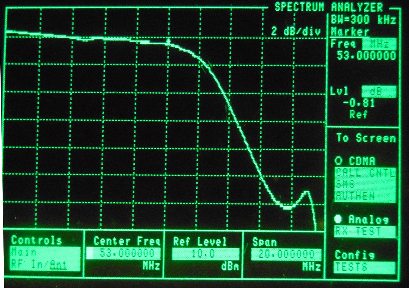
Here is a sweep from antenna connector to RX connector on a modified all digit serial number TK690H. Return loss was 20 dB on 6 meters.
Radio Adjustments:
Verify that the radio is on frequency and adjust if necessary.
For amateur service decreasing the TX output to reduce excess heat from the increased duty cycle makes good sense. 75% to 80% or 80 watts is a good choice.
For amateur service increasing the maximum deviation from 4.0 KHz with tone to about 4.8 KHz with tone will give the audio more punch. The tone deviation should remain at about 700-750 Hz.
The open squelch value may be too tight for some and you should adjust it accordingly.
Many of the radio adjustments are soft pots and can be adjusted from the front panel. Hold down the PF1 key (first button to the right of the knobs) and turn power on. This will put the radio in Panel Test Mode. Use the PF1 and PF2 keys to select the test channel (7, 8, and 9 are the added 6-meter test channels). Press the "^" key to enter the Panel Tune Mode. In this mode PF1 and PF2 select the item, PF3 and PF4 select the value, and PF5 saves the value. Cycle the power to go back to User Mode.
FREQ_XXX - adjust the frequency (master oscillator warp). POW_XXX - adjust the transmitter power. MAX_DEV - adjust the maximum deviation for voice plus tone. SQ_O_XXX - adjust the squelch open point.
Unlike the TK-6110, no tuning adjustments were necessary for the receiver to cover the 6-meter range.
Kenwood Software:
Use the KPG-44D V2.01 programming software along with a KPG-43 Programming Cable. You will also need a Hex editor such as the free HexIt utility to change frequencies above 50.0 MHz.
The KPG-44D software will not allow you to enter a frequency greater than 50.0 MHz. The solution is to create the data file with values 10 MHz lower, i.e. 42.525 MHz instead of 52.525 MHz. After a data file has been created or modified, exit the KPG-44D software and use a hex editor to change any 4x.xxx frequencies to 5x.xxx frequencies. The frequencies will appear correct when the data file is loaded into the KPG-44D software. Remember, everything can be changed with the KPG-44D software except the frequency entries above 50 MHz.
The HexIt utility is a very simple Hex editor that runs in DOS or Command Mode. If you are using Windows, open a Command Prompt. CD to the directory where you have stored the data file. Start HexIt with the data file filename as the argument. At about address 1840 you should start seeing the channel programming data, one channel per line. For 53.01 MHz, which you programmed at 43.01 you will see a line like this:
XX...00 10 30 04...00 10 20 04...
This translates to 43.01 RX and 42.01 TX. To change it to 53.01 RX and 52.01 TX change the 4's to 5's so it looks like this:
XX...00 10 30 05...00 10 20 05...
You should be able to go right down the two columns, transmit and receive, and change all the 4's to 5's in a matter of seconds. Save the file when you're done.
After you exit HexIt, run the KPG-44D software and check that you have made the changes correctly. You can now load the data file into the radio.
An alternative to hex-editing the DAT file is to use Pete N2MCI's conversion program. You enter your frequencies in the 40-43 MHz range and save the DAT file, then run Pete's program to convert those to 50-53 MHz frequencies. You can then load the DAT file and write it to the radio. A copy of Pete's program can be found here and it should work fine on all Windows systems. You have to open a command prompt, change to the directory where the DAT file and KWLBHEZP program are located, and run it.
Credits and Acknowledgements:
Hexit157a.zip (hex editor) can be found at http://www.mklasson.com/hexit.php.
Thanks to John W1GPO who performed the transmitter low-pass harmonic filter modifications.
Thanks to Bob WA1MIK who turned these notes into an article for repeater-builder.
Thanks go to Pete N2MCI for writing and providing his KWLBHEZP programs that work on DAT files for both TK-690 and TK-6110 radios.
Contact Information:
The author can be contacted at: his-callsign [ at ] arrl [ dot ] net.
Back to the top of the page
Up one level (Kenwood Index)
Back to Home
This page created on 07-May-2020.
Article text and photos © Copyright 2020 by Roger Coulson WA1NVC.
Converted to repeater-builder format by Robert Meister WA1MIK.
This web page, this web site, the information presented in and on its pages and in these modifications and conversions is © Copyrighted 1995 and (date of last update) by Kevin Custer W3KKC and multiple originating authors. All Rights Reserved, including that of paper and web publication elsewhere.