Back to Home
By Matt Krick K3MK
HTML'd for repeater-builder by Mike Morris WA6ILQ

|
Up one level (Kenwood index) Back to Home |
Brute Force Hacking the Kenwood TKR-720 and TKR-820 Series Repeaters By Matt Krick K3MK HTML'd for repeater-builder by Mike Morris WA6ILQ |
|
These make great little repeaters. They also are becoming fairly common on the surplus market as companies are caving into the idea that digital cellular is a better alternative to NBFM. If you are reading this article then I am sure you bought one for cheap or acquired one by some other means with the thoughts that you could drag it into the ham band.
So lets begin. First lets make sure the repeater works. Start by connecting a watt meter with dummy load to the TX port after taking the bottom plate off and bypassing the duplexer if it has one. Use a 25W 200-500 MHz or 400-1000 MHz slug or the closest thing you have. Loosen the squelch until the repeater goes into transmit mode, remember to press the repeat button on the front panel in.
If it won't go into transmit then turn the unit off, pull the covers and remove the 93C46 EEPROM from the controller board (This is the little board that is about 3 inches by 5 inches and sits above the radio chassis). This chip holds the PL / DPL information and with this chip removed from the socket the repeater will activate on COS only.
Once the tone EEPROM is out you can turn it back on and it should repeat. Got RF power? Good. Label the tone chip and set aside as we will deal with him later.
Next step is to take write down the voltage on the from the test points besides the VCOs. The VCOs are located under the metal tray that the controller sits on. This should be some where around 4 volts DC.
Now we have to come up with a way to change the data that sets the frequency of the repeater. For some reason the chip that does this is on the circuit board on the front panel of the repeater.
I was originally told that "Either a KPT-20 or KPT-50 is need to program those. No way around it." That sounds like a wager to me. Sure if you have a Kenwood dealer around that you can borrow one from or willing to spend more than you bought the repeater for this is a sure fire method. Oh, you will also need the KPG-21D software, but it will not allow operation into the ham bands and it has some serious compatibility issues running on modern hardware.
Unsolder the only 93C46 EEPROM that is on the front panel board. This chip holds the RF frequency information. Use what ever method you like to remove it, I prefer my trusty static free Soldapulit. Be careful not to rip any leads off the package when removing it. Install an 8 pin DIP socket in the hole that used to hold the frequency chip and solder it in place.
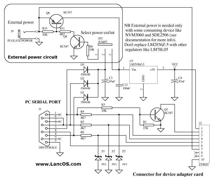
Now we need to get the data out of the frequency chip. I built the serial port to EEPROM interface found here: http://www.lancos.com/e2p/siprog_base.png and at http://www.lancos.com/e2p/si-prog-v2_2.pdf in order to be used with the device programming software "Pony Prog" that is at http://www.lancos.com/prog.html. You have to build the base board and then the socket for the device you wish to program. I replaced the LM2936Z-5 in the schematics with a 5.1 V Zener diode fed with a 330 ohm resistor to generate the +5vDC needed, and a BC547 is the European equivalent of a common 2N3904. This way all parts can be obtained from your local Radio Shack, or your parts box depending on how much home brew you do so well.
So once you have the interface built and running you can read the EEPROM contents. The settings take a little while to get used to. All you want it to output to is a raw binary dump with no header information saved.
Open the dump with a hex editor. I like XVI32, http://www.chmaas.handshake.de/delphi/freeware/xvi32/xvi32.htm. Pretty hard to beat free. Now for some reason the Pony Prog spit out information that is interleaved. This is evident by the way the data is arranged at address &H7A, Which on my dumps is 8R021N. On a Kenwood KPG-21D generated image this should say R820N. Anyway, it makes the hex coding easier to understand when doing the channels. If you are using a different chip program that did it right you will have to swap the bytes around, i.e C884 to 84C8. It should be obvious when you do the calculations and your frequency is in the 650 MHz region.
The receiver frequency data starts at &H00 and it 2 bytes long. In my binary image I have &H8338. Open up the windows calculator and place it in scientific mode (Or you can use a decent calculator that will convert Hex to decimal such as the TI-36X.). Press the "Hex" button and enter in the data that you have. Then press "Dec" to chage it to decimal.
&H8338 = 33592 decimal.
Now we multiply this by the channel stepping. 12.5 for the UHF TKR-820 and 5 for the VHF TKR-720.
33592 times 12.5 = 419900.
Now we add the IF frequency (21.4 MHz)
419900 plus 21400 = 441300
That's 441.300 MHz. You still with me? Good.
The transmit side is the exact same thing, but starts at &H02. I find this odd that both the transmit side and the receive side use IF frequencies on the synthesizers, but whatever.
Now that you have reverse engineered what channels the repeater is on, Stick that chip back in there. You get to do... More arithmetic.
Figure out the target frequency you want and we will go from there.
I want mine to receive on 443.400 MHz...
So we subtract the IF frequency: 443400 minus 21400 = 422000
And divide by the frequency step: 442000 divided by 12.5 = 33760
Convert to Hex: 33760 = &H83E0. Write down this information.
And to transmit on 448.400 MHz....
448400 minus 21400 = 427000
427000 divided by 12.5 = 34160
34168 = &H8570 hex
Make a copy of the original binary file and we will edit the copy.
Starting at the first address enter the receive data then the transmit data.
"83 E0 85 70 FF FF FF FF FF"......
"FF" signifies no data and should fill the contents to the EEPROM up to address &H7A which is "38 52 30 32 31 4E" (8R021N)
Now place the frequency chip into your programmer and fire the new binary file into it. Place it back into the repeater.
If you did a large frequency jump your repeater will appear to be "Bricked". Don't worry. You will need to adjust the trimmers on the VCO cans so that the test point voltage is either the voltage you wrote down in step 1 or as close to 4.0 volts as possible, which ever way you want to do it. Also there are some helical coils for the receiver's pre-selector, feel free to adjust these for maximum sensitivity.
As long as you have a service monitor out, now would be a good time to retune your internal duplexer (if there is one). Remove the duplexer out of the bottom of the repeater cabinet and follow the instructions here: Notch-Only Duplexer Tuning. The internal duplexer on these units is designed to protect the repeater only from itself and will do nothing to provide protection from any other systems at the same site.
Moving on to the EEPROM chip that controls the PL/DPL...
The PL data starts at the same locations as the synthesizer data. Address &H00 controls the receiver and &H02 is the transmitter.
After pulling out some hair and then sitting over a chart with mass quantities of hot chocolate, I came to the conclusion that the frequency formula is this:
&HC2E9 minus &HC000 = &H02E9.
&H02E9 equals 670 decimal
670 divided by 10 = 67.0 Hz.
I need 123.0 Hz in my repeater, so...
123.0 times 10 = 1230
1230 equals &H04CE
&H04CE plus &HC000 = &HC4CE
"FF FF" is what you would program if you want carrier mode.
So, "C4 CE C4 CE"... Would be what you put in to the EEPROM from the controller board for both 123.0 Hz on both receive and transmit, or C4 CE FF FF for 123.0 Hz on receive and no encode on transmit. What?!? You don't like 123.0 Hz? Too bad, it is part of the master plan to make all repeaters in the world carrier access or 123.0, muhahahaha... Oh wait...
Looks like everything from 67.0 to 250.0 Hz can be generated this way. The board also supports Digital Quiet Tone / DPL / DCG, but it looks way complicated to figure out what is what and I have no motivation to pursue it as I do not have any DQT radios to experiment with.
It may be a better option for you to install a PL board such as a Com-Spec TS-32 or a TS-64 as this only works with the internal controller, and since the internal controller has no way to ID the repeater it makes it pretty useless on amateur radio channels. But you should be able to tap the logic out of the Kenwood PL decoder section to run an external controller so this is another thing that is entirely up to your preferences.
Happy hours testin' and burnin'.
Matt, K3MK
Note from WA6ILQ:
Here are local copies (i.e. on the repeater-builder server) of the files mentioned above:
All four of the above files as a single 980 KB ZIP file:
tkr-n20-bit-banging-package.zip.
If anyone would like to do an add-on article to this one that describes how to program
Digital Quiet Tone / DPL / DCG please consider this an invitation to do so. Just mail
it in to one of the Repeater-Builder staff members.
Back to the top of the page
Up one level
Back to Home
This page originally posted on Monday 06-Jul-2009
Article text © Copyright 2009 Matt Krick K3MK
Artistic layout and hand-coded HTML © Copyright 2006 and date of
last update by repeater-builder.com.
This web page, this web site, the information presented in and on its pages and in these modifications and conversions is © Copyrighted the page creation date and (date of last update) by Kevin Custer W3KKC and multiple originating authors. All Rights Reserved, including that of paper and web publication elsewhere.
The Repeater Builder's site does not evaluate the accuracy of materials created by persons beyond its control or supervision. Therefore, although this site links to many additional web sites, The Repeater Builder's site is not responsible for the availability of or the accuracy of any materials contained within those web sites.