Back to Home
By Brad Andrews KB9BPF
29 December 2007

|
Up one level Back to Home |
Additional Digital Outputs for the Link RLC-4 Repeater Controller By Brad Andrews KB9BPF 29 December 2007 |
|
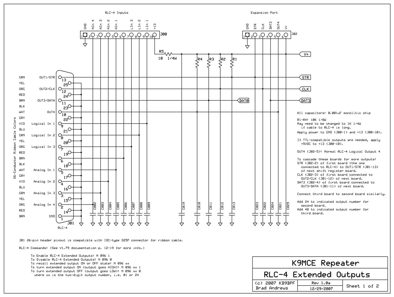
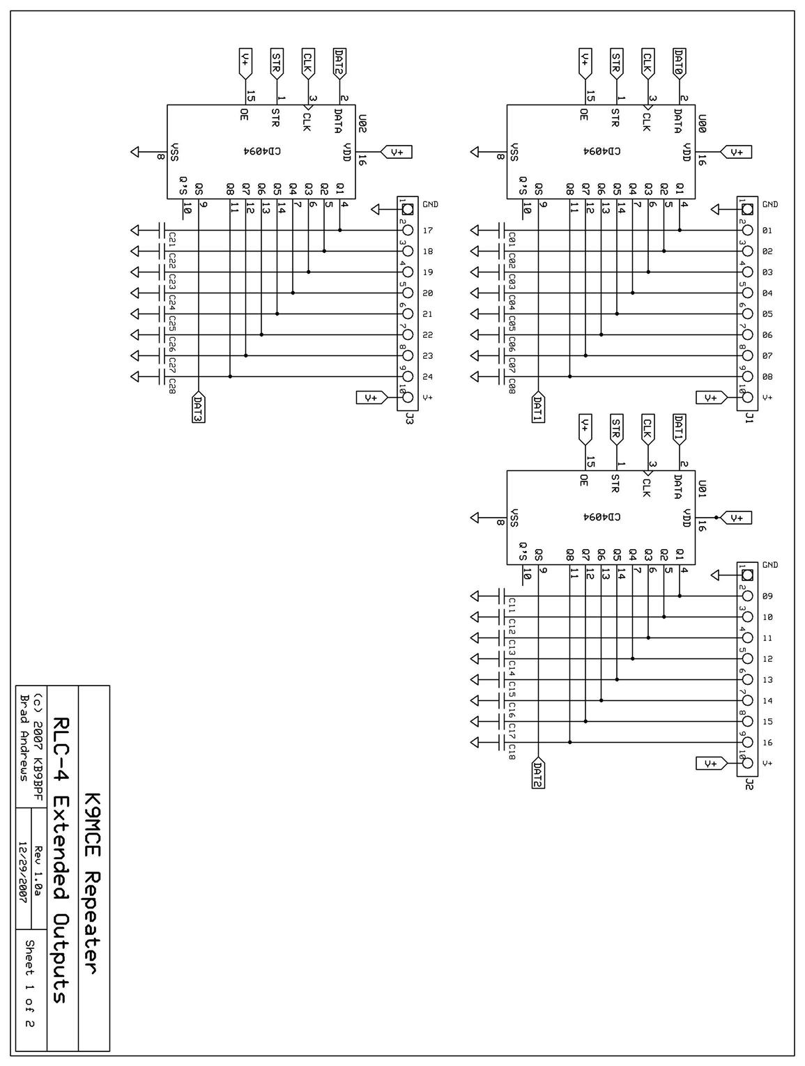
For several years the K9MCE Macoupin County Radio Club 146.865 repeater has been using a Link RLC-4 Controller. Recent upgrades to our system, including voter control and ability to enable and disable PL encoders and decoders on the various controller and voter ports, required more digital output control lines than are included on the stock RLC-4. The RLC-4 V1.79 manual offers a solution to this problem: expanded outputs using outboard shift registers.
(By the way, the hardware modification needed to make the remote receiver point-to-point link audio sound good is described on the Hamtronics page at this web site, and an article will be forthcoming which will describe my modification to the WB2WHC voter, allowing it to be controlled by logic signals from the controller.)
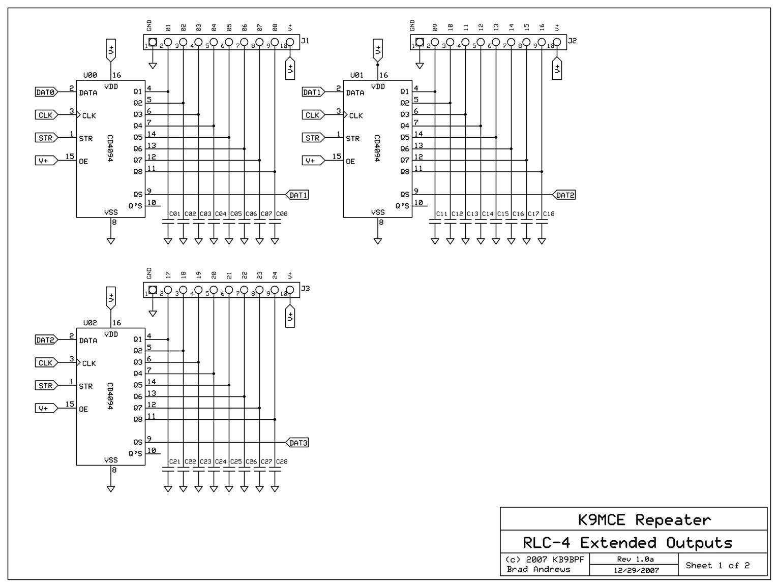
I read the Link RLC-4 book and studied materials on the Link web site in order to discern how the RLC-4 expects the external shift register circuitry to work. I built the circuit and verified that the latch logic sense, etc. at the RLC-4 outputs is correct for the 4094 shift registers with no inverters or gating.
Some tips to others, things to keep in mind about this, collected for future reference:
Here is a synopsis of the circuit:
To cascade these boards for more outputs:
RLC-4 Extended Output commands: (Refer to V1.79 documentation pages 12-19 for more info.)
Note that in the commands below the xx is the two-digit output number with a leading zero if
necessary, i.e. 01 or 24.
Click on the images below to enlarge them:
| |||||||||
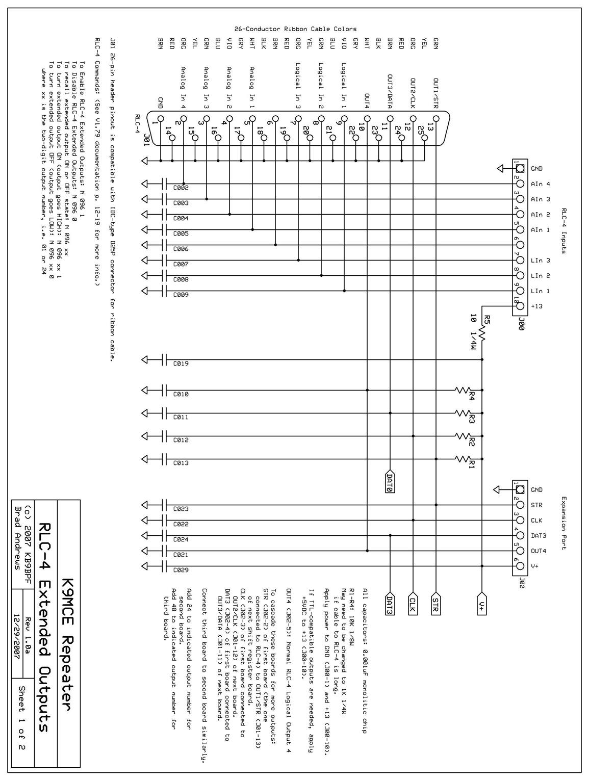
Click on the links below for rotated versions of the above files (oriented for printing). These are large files, you may want to select the "Fit to page" option in your printer properties when printing.
Click on the links below For the Express PCB files:
Acknowledgements and Credits:
The schematic was developed from the information in the Link manuals and
from information on the Link web site.
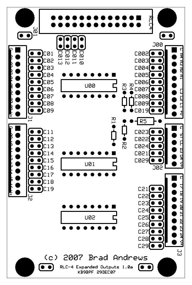
I desired a professional-quality result, so I had PC boards made. They were
laid out with the free software from ExpressPCB, and the boards were made by
them. There is no reason that a perf-board version would not work just as
well.
Contact:
Brad Andrews KB9BPF can be contacted at (callsign) //at// arrl //dot// net
(the email address has been disguised in an attempt to thwart the spambots).
Back to the top of the page
Up one level
Back to Home
This page originally posted on 18-Mar-2008
Artistic layout and hand-coded HTML © Copyright 2008 and date of
last update by repeater-builder.com.
Photos, drawings and article text © Copyright 2008 by Brad Andrews KB9BPF.
This web page, this web site, the information presented in and on its pages and in these modifications and conversions is © Copyrighted 1995 and (date of last update) by Kevin Custer W3KKC and multiple originating authors. All Rights Reserved, including that of paper and web publication elsewhere.


