Step 1: Remove the MICOR power amplifier PC Board and discard. It is not tunable to 222MHz. Save all hardware.
Step 2: Unsolder the wires from the Positive feedthrough capacitor and unscrew it from the casting.
Step 3: Install the Positive feed through capacitor in the hole next to the negative feedthrough.
Step 4: Re-connect the positive wire and filter cap to the feedthrough.
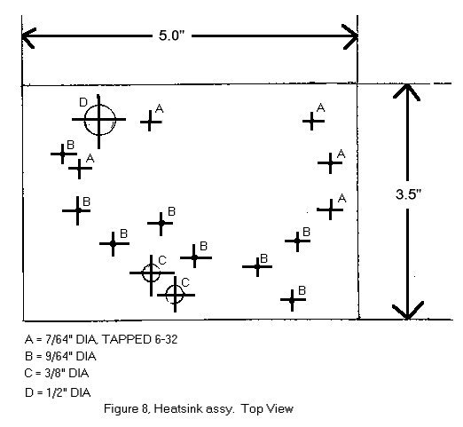
Step 5: Construct the Toshiba power module based amplifier per the schematic. (fig 6). Mount the module to a 3/16" thick X 3 ½" X 5" aluminum plate where the original PA board was mounted (Fig. 8). Use heat sink compound between the module and plate, and between the plate and casting.
Step 6: Wire the PA to the Exciter output, +12V, Gnd., and to the Harmonic filter.
Step 7: Wire the Blue power control wire to the Base of
the pass transistor. (Mounted where the old PA board Pass transistor was
with new insulators etc)
Here's a photo of the finished PA.

Page recreated by: Kevin K. Custer W3KKC
Copyright 1998 SEITS, N5XMT and W3KKC.