Comprehensive Conversion of
the Motorola®
MICOR® High-Band Exciter
for use
in the 222 MHz. ham band.
** New approach using a different multiplication
method **
By Kevin K. Custer W3KKC and M. Scott Zimmerman
N3XCC
Image by David A. Cooley N5XMT
Concept:
To provide a modification
for MICOR highband exciter boards for use in the 222 MHz ham band
from a simpler method that allows operation at 18 times the crystal frequency
instead of 12 times as in all other modifications found as of the original
date of this writing. This procedure will work on all versions of
the MICOR high-band exciter including the Phase Modulated 3 pin, 4 pin
Mobile, and True Frequency Modulated 4 pin Mobile and Station types.
Description:
I have tried several
approaches modifying the MICOR exciter for 1¼ meter (222 MHz.) use.
This modification is the result of approximately 25 hours of engineering
and testing, using an old mobile frame for a test bench. In the past
we have had some stability and modulation issues when modifying both PM
and FM MICOR exciters for use in the 222 ham band using the existing methods.
The instability and modulation issues stem from the crystal manufacturers
having the inability to cut consistent crystal inserts at 18 MHz;
the fundamental of all other 220 exciter modifications found on the internet
or otherwise as of this writing.
Since the high-band MICOR
exciter was designed to operate at a 12 MHz fundamental, and the
channel elements are ultimately more stable at this fundamental, the solution
we found was to operate the exciter in a fashion that changes the multiplication
factor from the original 12 times to 18 times. The first few tuned
stages are operated at 12 MHz as original and the latter stages changed
to allow for the 18 times multiplication. This results in a modification
that is ultimately simpler, cheaper, and provides better stability because
the crystal manufacturer can build a common crystal to known specifications.
As for the modulation problem, modulating an 18 MHz crystal seems
a bit more difficult as well as the known fact that crystal manufacturers
are cutting the crystals at a slightly higher load capacitance than original.
This higher load capacitance results in better overall temperature stability,
however, in an FM channel element the result is usually less than adequate
deviation without distortion; in other words the crystal isn't rubbery
enough. It should be noted that these problems are not the fault
of the crystal manufacturers, as they are only trying to make something
work that was never intended to do so by Motorola.
The modification described
here allows a K1007 or KXN1019B channel element to be built to original
Motorola specifications or if you/they choose slightly higher load capacitance
without worry of inadequate deviation. How is this so you ask?
The crystal is now multiplied more times requiring less deviation *at the
crystal frequency* for the desired amount of final deviation.
Theory of operation:
Say you have a crystal element at approximately 12.5 MHz. The
tripler output (Q403 TLD8262 "B" Suffix, or Q401 "A" suffix) will be at
37.5 MHz or three times the crystal frequency, just like a regular high-band
exciter, so, how do we get the 220 output from the exciter?
The 1st doubler transistor (Q404) and succeeding stages, L405 and L406,
now operate as a tripler.
So, what frequency does L405 and L406 tune (output of 1st doubler?)
Using the example of 12.5 MHz fundamental, 112.500 MHz. (12.5 X 3
X 3).
Okay, what frequency does L407 and L408 (output of 2nd doubler) tune?
Using the example of 12.5 MHz fundamental again, 225.000 MHz.
Is the original multiplier scheme different? Yes, 18 times total.
[12.xxx] X3, X3, X2
Please realize this mod refers to the 8262B (suffix "B") "type" mobile exciter, however the cap designators are different for the suffix "A" and Station exciters. Just use the correct substitute value capacitors for the corresponding location in the "A" or Station type exciters.
Crystal Information:
The exciter channel element
(K1007 for PM, KXN1019B for FM) still operates at 12 MHz as original,
however the multipliers are now operating on a factor of 18 times instead
of 12. No modification to the channel element is required.
The multiplier provides X18 of the crystal frequency, and the crystal
formula is Fcr = Fo divided by 18.
Fcr = the crystal frequency, and Fo = the operating
frequency.
If the particular crystal vendor you choose cannot predict the crystal frequency, you can do an inverse calculation to generate the equivalent high-band operating frequency and give that to the crystal vendor. Simply take your 220 operating frequency and divide it by 18, and then multiply that result by 12. The result will be the same no matter which method is used.
Note: This modification will allow the use of surplus 2 meter or high-band channel elements in the 146.6666 to 150.00 MHz range for testing the exciter between 220 and 225 MHz respectively.
Purchasing Crystals or Channel
Elements:
The crystal for the exciter
channel element for use in the 220 exciter can be purchased from Bomar
Crystals. Specify the crystal is for a "K1007" if you have a PM exciter
or a "KXN1019" for an FM exciter and simply give them the desired operating
and crystal frequencies and they will make a crystal and mark it accordingly.
Bomar Crystals
Modification:
The modification involves
changing 10 capacitors (3 silver mica and 7 disk ceramic) and retuning
the exciter to your frequency on the 220 band.
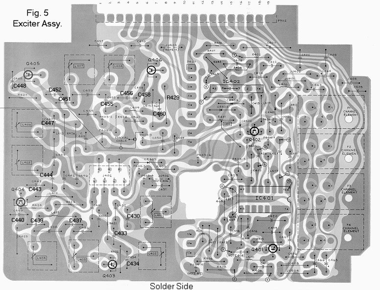
Refer to Figure 5 for the part locations.
Remove the exciter from radio set and change the following components to
the new values shown.
Be certain to replace the components with the same type of part:
C443 = 15 pf 5% Silver-Mica
C444 = 12 pf 5% Silver-Mica
C447 = 10 pf NP0 Disk
C448 = 15 pf NP0 Disk
C451 = 4.7 pf NP0 Disk
C452 = 7.5 pf NP0 Disk
C455 = 3.9 pf NP0 Disk
C456 = 4.7 pf NP0 Disk
C458 = 1.5 pf NP0 Disk
C460 = 75 pf 5% Silver-Mica
R429 = 49 - 180 ohm 1/2 watt *see below for more information*
Tune the exciter per the Motorola manual or tuning instructions found elsewhere on this site.
* The exciter should produce approximately 250 mW. If something
other than 250 mW is needed for driving an outboard amplifier, simply change
the value of R429 to obtain the desired drive level. Don't go below
the original value for R429. Usually this value needs no changing
to get 250 to 300 mW which after the exciter is filtered by the exciter
BPF, nets 200 mW of power; the correct drive level for the Toshiba
S-AV15 or similar Japanese power module.
Copyright March 19 2004, Kevin K. Custer W3KKC
Updated December 3, 2004 with addition of "theory of operation".
Updated March 21, 2018 to eliminate custom crystal and channel element stuff.
All Rights Reserved!