Back to Home
Motorola K1003A
Channel Element
By Robert W. Meister WA1MIK
With Additional Input from Glenn Little WB4UIV

|
Up one level Back to Home |
What's Inside a Motorola K1003A Channel Element By Robert W. Meister WA1MIK With Additional Input from Glenn Little WB4UIV |
|
There is already a lot of channel element information on Repeater-Builder, but a little more never hurts.
Background:
I acquired a 72 MHz link receiver that contained one of these elements. I subsequently purchased an assortment of elements that had more than half a dozen K1003As in it, so taking one apart and possibly ruining it wouldn't cost me much. Eventually I planned on purchasing just a crystal for one without sending it out for compensation. This saves a lot of money, and for a low-band receiver that would operate inside my house I didn't care about temperature stability.
John W1GPO had a bunch of K1004A low-band transmit elements. He dissected several and supplied me with parts values for that element. The circuitry is identical. The low-band MICOR transmitter is phase-modulated and it doesn't modulate the actual crystal, which IS done on other MICOR frequency-modulated transmitters.
Construction:
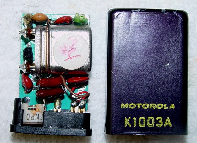
The thin anodized aluminum can is held on with pressed-in tabs at the side that can be pried out with a thin pocketknife blade. The metal can be straightened out with a pair of needle-nose pliers afterwards. The plastic base and the circuit board slide out as an assembly. There is one thin layer of Mylar plastic wrapped around the entire assembly, and some insulating fish paper is glued to the back of the circuit board. A small piece of foam rubber inside the top of the can keeps the assembly from moving. The photo below shows the circuit board and base removed from the can:
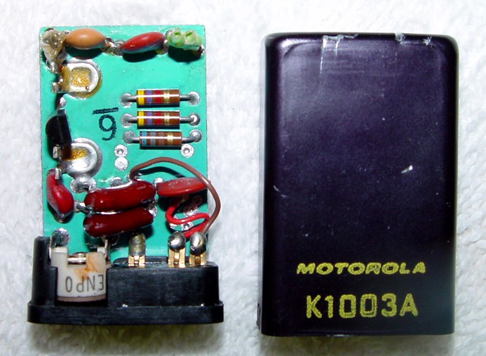
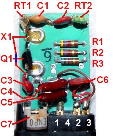
A few parts are hidden under the crystal, so I removed it and took another photo:
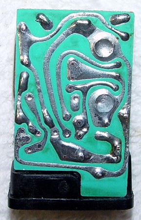
After removing the sticky paper from the back, you get to the wiring side of the circuit board:
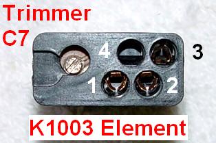
Here's a photo of the plastic base with its three socket contacts and the trimmer capacitor. As this element is only used for low and mid-band receive, there is no 4th contact that could be found in some other elements.
I spent some time drawing the schematic diagram. First I assigned designations to the various parts. This is the identification scheme I came up with:
After several hand revisions, I ended up with the following schematic (click on it to enlarge it):
The crystal frequency is 13280.00 kHz. The channel element frequency is 45.100 MHz. The formula for this radio/element combination is:
K1003A Crystal Frequency = (Operating Frequency - 5.26 MHz) / 3
The K1004A transmit channel element uses a simpler formula:
K1004A Crystal Frequency = Operating Frequency / 6
| Parts List | ||
|---|---|---|
| Name | K1003A Description | K1004A Description |
| C1 | 7.0 pF NP0 | 7.0 - 7.5 pF NP0 |
| C2 | 7.5 pF NP0 | 9.0 - 13.0 pF NP0 |
| C3 | 20 pF N470-N2200 | 18 - 20 pF N470-N2200 |
| C4 | 220 pF NP0 | 220 pF NP0 |
| C5 | 190 pF NP0 | 190 pF NP0 |
| C6 | 0.01 uF | 0.01 uF |
| C7 | 3.5 - 14 pF NP0 trimmer | 3.5 - 14 pF NP0 trimmer |
| Q1 | M9571 transistor | M9571 transistor |
| R1 | 4.7k | 4.7k |
| R2 | 4.7k | 4.7k |
| R3 | 680 | 2.2k |
| RT1 | 17-71k thermistor | 17-71k thermistor |
| RT2 | 140-160 Ohm thermistor | 140-160 Ohm thermistor |
| X1 | ~13 MHz crystal | ~7 MHz crystal |
Glenn Little WB4UIV did additional analysis of the temperature-compensation components of the K1003A channel element. He supplied the data below.
| Crystal Freq | Crystal Marking | C1 | C2 | C3 | RT1 |
|---|---|---|---|---|---|
| 12406.666 | none | 7.5 pF | 8 pF | 20 pF N1500 | Bead Green |
| 12613.333 | 37 | 7 pF | 7.5 pF | 20 pF N1000 | Bead Red/Green |
| 12613.333 | -3 | 7.5 pF | 7 pF | 20 pF N150 | Bead Orange/Green |
| 13986.666 | S8421 | 7.5 pF | 8 pF | 20 pF N1500 | Bead Red |
| 13986.666 | S8321 | 7.5 pF | 8 pF | 20 pF N1500 | Bead Red |
| 14006.666 | none | 7.5 pF | 7.5 pF | 20 pF N1500 | Bead Red |
| 14006.666 | S8420 | 7.5 pF | 7.5 pF | 20 pF N1500 | Bead Green |
| 14006.666 | S8321 | 7.5 pF | 8 pF | 20 pF N1500 | Bar Green |
| 14306.666 | 10 | 7.5 pF | 7.5 pF | 20 pF N750 | Bar Orange |
| 14913.333 | S8452 | 7.5 pF | 7 pF | 20 pF No TC | Bar Yellow |
| 14913.333 | -19 | 7.5 pF | 7 pF | 20 pF N470 | Bead Yellow |
| 14920.000 | H09 | 7.5 pF | 8 pF | 20 pF N1500 | Bead Green |
| 14920.000 | AUL S8439 | 7.5 pF | 8 pF | 20 pF N1000 | Bead Red |
| 14920.000 | 73 | 7.5 pF | 8 pF | 20 pF N1500 | Bar Yellow |
| 14920.000 | H03 | 7.5 pF | 8 pF | 20 pF No TC | Bead Green |
| 14920.000 | VND 730 | 7.5 pF | 7 pF | 20 pF N1500 | Bead Red |
| 14933.333 | K-WJO | 7.5 pF | 7 pF | 20 pF N1500 | Bead Red |
| 14933.333 | S8246 | 7.5 pF | 8 pF | 20 pF N2200 | Bead Red |
| 14986.666 | 52 | 7.5 pF | 7.5 pF | 20 pF N1500 | Bead Red/Green |
| 15010.150 | 503855-1 EG&G | 7.5 pF | 7 pF | 20 pF N1500 | Bead Red |
| 15013.333 | S8426 | 7.5 pF | 9 pF | 20 pF N3300 | Bead Green |
| 15020.000 | 315 | 12 pF | 7 pF | none | Bar Black |
| 15033.333 | ICM 160036 (34) | 7 pF | 6.5 pF | 20 pF N750 | Bead Green |
Notes:
Contact Information:
The author can be contacted at: his-callsign [ at ] comcast [ dot ] net.
Back to the top of the page
Up one level
Back to Home
Article text, photos, schematic, and HTML conversion Copyright © 2008 by
Robert W. Meister WA1MIK.
Article originally created 24-Oct-2008
This web page, this web site, the information presented in and on its pages and in these modifications and conversions is © Copyrighted 1995 and (date of last update) by Kevin Custer W3KKC and multiple originating authors. All Rights Reserved, including that of paper and web publication elsewhere.