BI-LEVEL SQUELCH / PL FOR REPEATERS
Modification Courtesy of SEITS
As no one wants to listen to discriminator noise, the proper operation
of the squelch circuit in any FM radio is vital. In a repeater, the squelch
/ COR is even more critical. The basic function of a squelch circuit is
simple: detect the presence of a radio signal and turn the speaker audio
on. That's really all they do.
SQUELCH METHODS
The first FM squelch circuits worked by detecting the presence of a
signal by measuring changes in the radios AGC (Automatic Gain Control)
voltage. This method worked poorly on weak signals so a better method was
developed, the noise operated squelch.
The noise operated squelch works by measuring the amplitude of the discriminator
white noise above the speech band. The phrase "above the speech band" is
the critical part. Your receiver's audio is split into two bands. One (from
300 to 3,000 Hz) contains the speech. Everything above 5,000 Hz is noise.
No intelligence is carried there.
When the radio hears a signal, the discriminator output begins to quiet.
That is, the amplitude of the white noise above the speech band begins
to drop. If we convert this AC high frequency noise to a DC signal, we
can measure it. We can compare it to a known reference voltage as well.
When the noise signal becomes weaker than the reference, the squelch circuit
turns the speaker on. When the noise is stronger than the reference, the
speaker is turned off.
TIMING IS EVERYTHING
In practice we can add some timing as well. By adding a simple resistor
/ capacitor timing circuit to our squelch, we can keep it from opening
on short bursts of noise that would be distracting. This still leaves one
problem. You can't have the squelch circuit close the audio immediately
either. If you do, the audio from fluttering signals like mobiles would
be badly chopped. This requires the squelch to have a time delay on the
release as well. This is called the squelch tail.
The drawback to this is that at the end of every transmission, you hear
a loud burst of discriminator noise until the time delay ends. Motorola
developed two cures for this annoying problem. One I'll discuss later.
The other was the development of the famous MICOR bi-level squelch IC.
MOTOROLA TO THE RESCUE
A little history here: The MICOR was Motorola's first true all solid
state trunk mount mobile. It was also the high water mark for squelch circuit
development. Since the use of PL and DPL (tone squelch) had not become
universal yet, Motorola put a great deal of effort into the MICOR's noise
squelch circuit. The heart of the squelch is a special IC, the M7716 (also
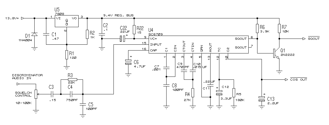
marked on early models as the SC6709 and M6709).
The M7716 is a complete bi-level squelch circuit on a chip. As far as
I know, it is found only in the MICOR radio. The schematic shows the M7716
complete squelch circuit. Note that the circuit could be added to any model
radio. Its open collector output from the 2N2222 can be interfaced to any
repeater controller.
The M7716 works like this. The IC contains two amplifier band pass filter
sections. These reject the speech audio and pass only the high frequency
discriminator noise. The amplifier filter is followed by a rectifier and
two amplitude detectors. If the signal provides at least 20 dB quieting,
(above 1uV on properly working receiver), the IC's logic circuit gives
no squelch tail. If the signal is below 20 dB quieting, (below 1uV, or
having some noise), there is a squelch tail. One long enough so there is
no chopping on fluttering signals.
Simply, the MICOR bi-level squelch works better than anything else on
the air. Not having a squelch tail on your repeater sounds great. Plus
you can tell how strong your signal is into the repeater. If there is no
squelch tail, you are full quieting; if there is a tail, you are noisy.
A very handy feature!
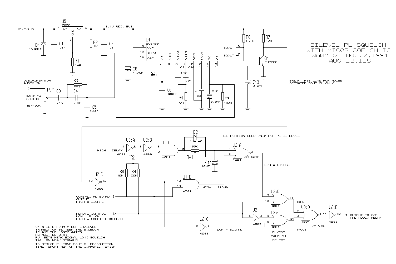
PL OPERATION
When I converted my repeater to PL operation (using a Com-Spec TS-32P
PL board) I lost my wonderful squelch tailless operation. The Com-Spec
had a long squelch tail on loss of the PL tone that sounded awful. Taking
a suggestion from Al Groff, KØVM, I came up with a simple logic circuit
that interfaces the Com-Spec PL board with the MICOR bi-level squelch IC.
The result is the best of all worlds.
The circuit gives you the choice of either noise (carrier) or PL squelch
operation. This is selected by a digital logic line input. This allows
the sysop to switch off the PL access remotely and keep the bi-level operation.
The circuit also allows squelch tailless PL operation as well. When the
PL access signal is above 1uV, there is no tail. When it is below 1uV,
there is a tail.
For proper operation, the Com-Spec TS-32P board must be modified. Resistor
R21 in the time constant circuit must be shorted. This eliminates the recognition
and release delay from the board. The output of the TS-32 is connected
to the bi-level board so when a signal is present, the output is high.
Pot RV1 in the bi-level circuit sets the duration of the weak signal squelch
tail.
CIRCUIT DETAILS
Here's the noise squelch circuit schematic. Click on it for a larger image.
Here's the full schematic with support for PL. Click on it for a larger image.
So far I have only been able to get this circuit to work with the Com-Spec.
The MX-COM PL IC cannot be modified to reduce the time constants. Schmidt
triggers U2:A & B are used to clean up the zero to one transition off
pin 12 of the M7716 IC without loading the M7716's time constant circuit
down. Note that you can ONLY use a CMOS inverter here such as the 4069.
The more popular 74C14 will not work as it is a 5V logic device. U2:E allows
you to take either a active high or low signal from the bi-level board
for your COR/controller.
The M7716 likes a clean regulated 9V supply. I used a trimmed LM7808.
You can use a dedicated 9 volt regulator like the 7809. The component values
in the M7716 circuit are critical. The capacitors should be high quality
mylar or polyester types, not ceramics. Test the electrolytics to be sure
they have accurate values.
Other than those precautions, the circuit is simple to build and install.
I've used it in my repeater since 1994 with no problems. Its very nice
to hear a repeater that snaps off quietly with no squelch tail on the air.
ANOTHER TRICK
Oh, what was that other trick that Motorola uses that I mentioned?
They have an additional delay circuit in their transmitter keying. When
you release the PTT button, the PL ceases transmission instantly, but the
transmitter carrier stays on the air for a few tenths of a second longer.
This way when the PL squelch opens on the receiver, you hear the full
quieting of the transmitting stations carrier during the squelch tail period.
Thus you hear no noise burst! Simple and very effective. The only problem
is that ham rigs have no transmit after ceasing PL delay. Thus we have
to use another method (in this case a very fast PL switch).
Can this circuit improve my newer Mitrek radio operation? Definitely
yes! The Mitrek came into being in a era where PL was universal. Motorola
installed a simple noise operated squelch almost as an after thought. They
didn't put much into it as they knew it would rarely be used. Personally,
I hate the sound of its operation. I consider the installation of the MICOR
bi-level squelch to be a great improvement in this radios operation on
the air.
AVAILABILITY
The last thing to cover is where can you get the wonderful M7716 IC?
This is a proprietary Motorola IC. It was built only for the MICORs in
the 1970's. It exists only as a rarely used Motorola spare part. Any Motorola
service shop can order the device for you and may even have it in stock.
Expect to pay at least $10 for a new one (fair price considering its rarity).
Lately word is that Motorola has exhausted its supply of M7716's. No
way they will ever be in production again. Lucky for us there seems to
be a good supply of old MICOR radios at hamfest. Remember all you need
is the audio output board from the radio. You don't give a damn what the
model, frequency range or power out is. All you want is a radio with an
intact audio board module.
You pull the covers off the radio, find the audio board and remove the
screws that hold it in place. Pull the board out and you can discard the
rest if you want! Seeing as junk MICORs sell for $5-10 this is a cheaper
way to get the IC then buying it new. The board has one transformer on
it and two DIP IC's. The IC you want is the one marked M6709 (IC202) on
the older chassis. The audio board may have various marking such as TLM4289.
While you are at it, if you find a UHF MICOR, with a 75 watt or 100
watt PA, they have another handy device in them. First, I could always
use another 100 watt PA deck as a spare for our UHF hub repeater. The MICOR
also had a very useful 70cm circulator and 50 ohm rejection load in its
PA deck. A very nice item indeed.
David Metz, WAØAUQ
Comments to davemetz@muscanet.com
Page recreated by: Kevin K. Custer W3KKC
Copyright 1998 SEITS
and W3KKC.
Back to Home