Back to Home
MICOR Receiver
for 435-450 MHz
By Robert W. Meister WA1MIK

|
Back to MICOR index Back to Home |
Improving the MICOR Receiver for 435-450 MHz By Robert W. Meister WA1MIK |
|
This is a detailed explanation of a procedure you can use to modify a UHF MICOR "M" range (450-470 MHz) receiver board so it operates adequately in the 435-450 MHz range. This is an enhancement to Kevin's text-only article.
These receivers are commonly found in a Spectra TAC chassis as well as base stations, mobiles, and satellite receivers. They will meet specs down to about 445 MHz; then things start deteriorating. While the receiver will, in general, perform adequately down to nearly 440 MHz, the crystal oscillator multiplier stages seem to run out of tuning range around 445 MHz. This condition can be fixed by replacing some components with values appropriate for the "L" range boards. You can do this one of two ways:
Padding is far easier and can be done without removing the receiver board from the chassis in only a couple of minutes.
Kevin's original article only mentioned replacing C117, C119, and C125. An e-mail received by Repeater-Builder from an ex-Motorola Service Shop technician contained a parts list for an export model MICOR that covered 420-450 MHz. This conversion included replacing several coils (L111 through L116) with parts that are no longer available. Information about C136 came from this source. Sensitivity with C136 padded is marginally better but you'd need sophisticated instruments to see it.
Here's a table showing the capacitor reference number, the original value for the "M" range (450-470 MHz), the value you'd need to replace it with (the "L" range), or the value you'd need to add across the existing component to get it to the "L" range. All values are in picoFarads.
| Cap. Ref. | Orig. Value |
Repl. With | Pad With |
|---|---|---|---|
| C117M | 18 | 27 | 9 |
| C119M | 33 | 39 | 6 |
| C125M | 8 | 12 | 4 |
| C136M | 10 | 47 | * 37 |
Ideally, the new parts should have the same temperature compensation factor as specified in the parts list below, but if your receiver will be in a stable temperature environment, regular NP0 caps should work fine.
Jameco doesn't have all the values in leaded variety. Mouser does, and I suspect Digikey does as well. The following are Murata monolithic radial-lead capacitors that I obtained from Mouser (remove the "81-" to get the Murata part number). Prices were as of April 2007:
Mouser Part Number Description Price
81-RPE5CH4R0C2P1B03B 4.0pF 50volts C0G +/-.25pF 2.5mm L/S $0.26
81-RPE5C1H6R0D2P1B03 6.0pF 50volts C0G +/-0.5pF 2.5mm L/S $0.30
81-RPE5C1H9R0D2P1Z03 9.0pF 50volts C0G +/-0.5pF 2.5mm L/S $0.33
81-RPE5C1H390J2P1Z03 39pF 50volts C0G +/- 5% 2.5mm L/S $0.26
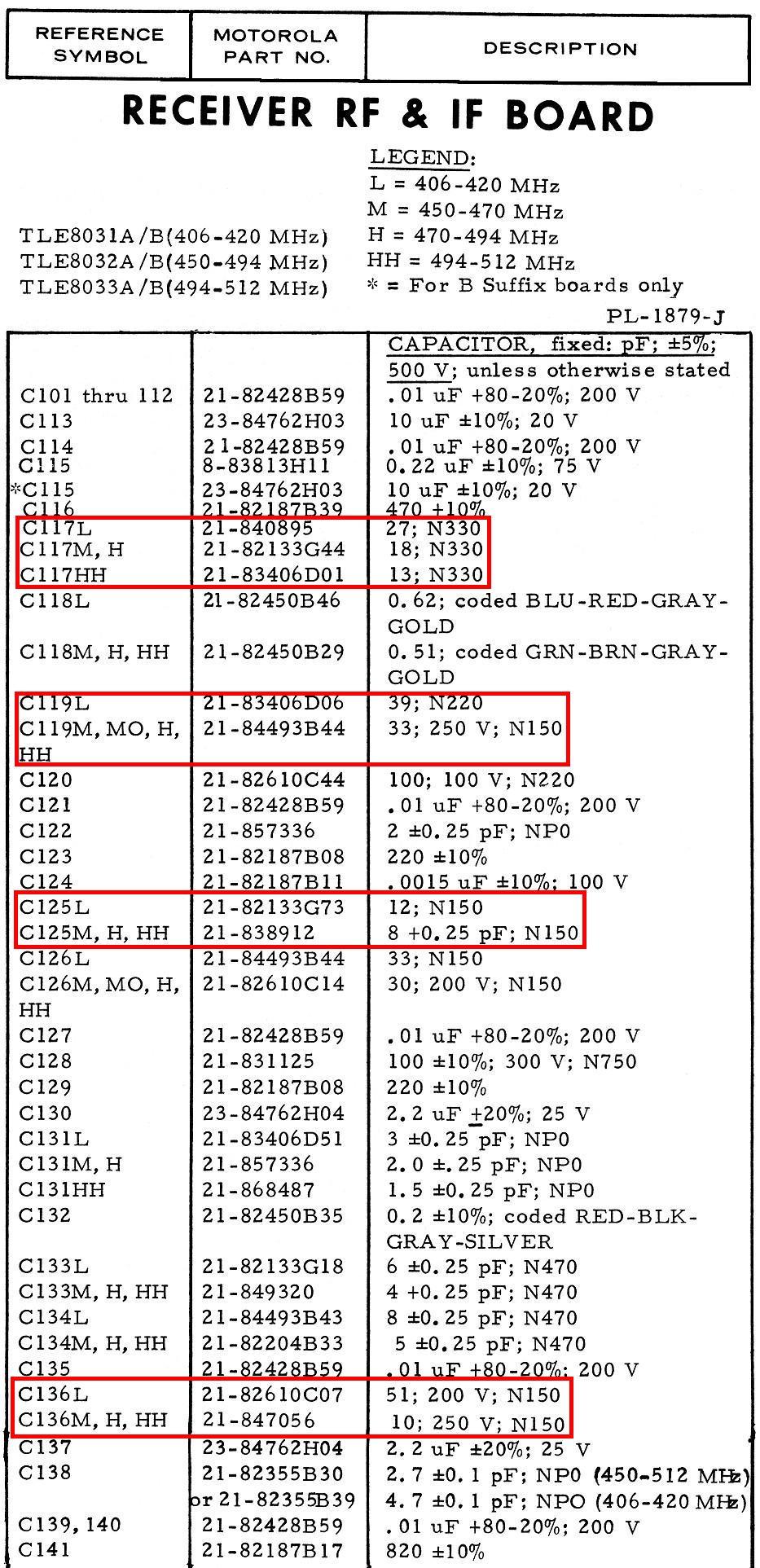
Here's a section of the original parts list:
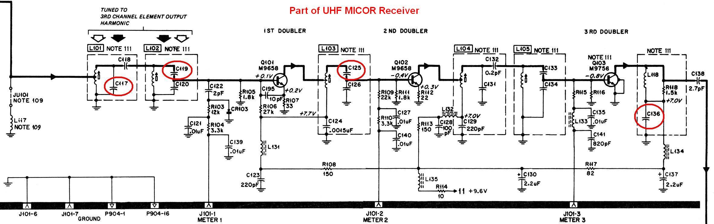
Here's the schematic showing the multipliers with the capacitors circled. Click on the image for a larger view:
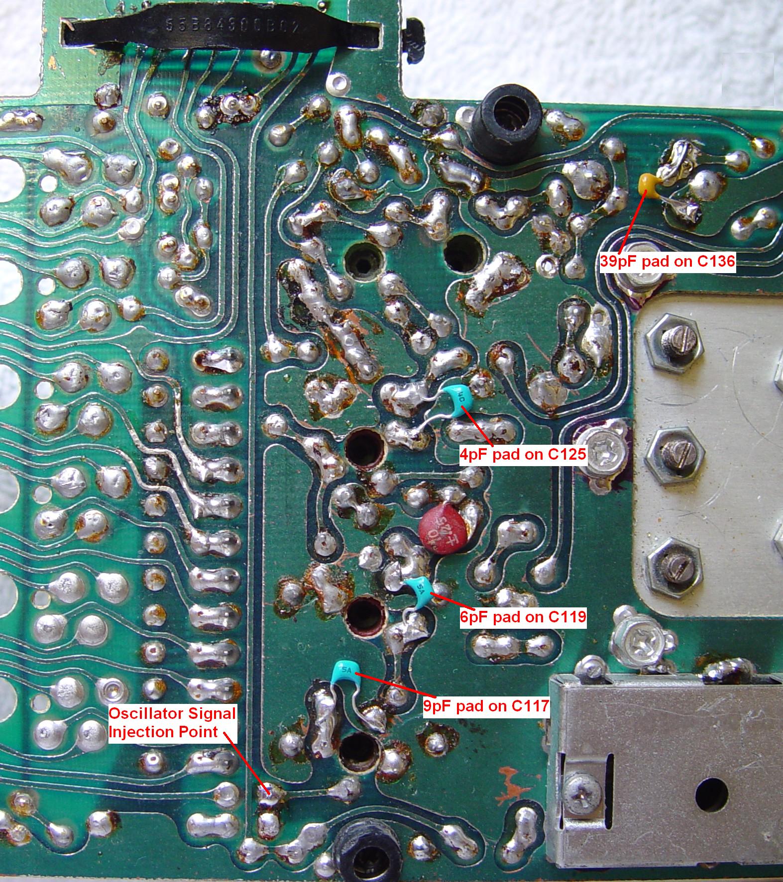
Here's the printed circuit board layout showing the location of the capacitors. Click on the image for a much larger (1.5MB) view:

There's plenty of room on the solder-side of the circuit board to solder additional capacitors across the existing ones inside the tuned coils. In fact, there may be some parts attached that way already (such as C195). Here's a photo of a board that has been padded according to this procedure. It's an old board (green, dirty fiberglass), built in early 1976, with a part number of TLE8032B stamped on it. The padding capacitor values are facing the circuit board. This board was modified and supplied by Dave N1OFJ. Click on the image for a much larger (500kb) view.
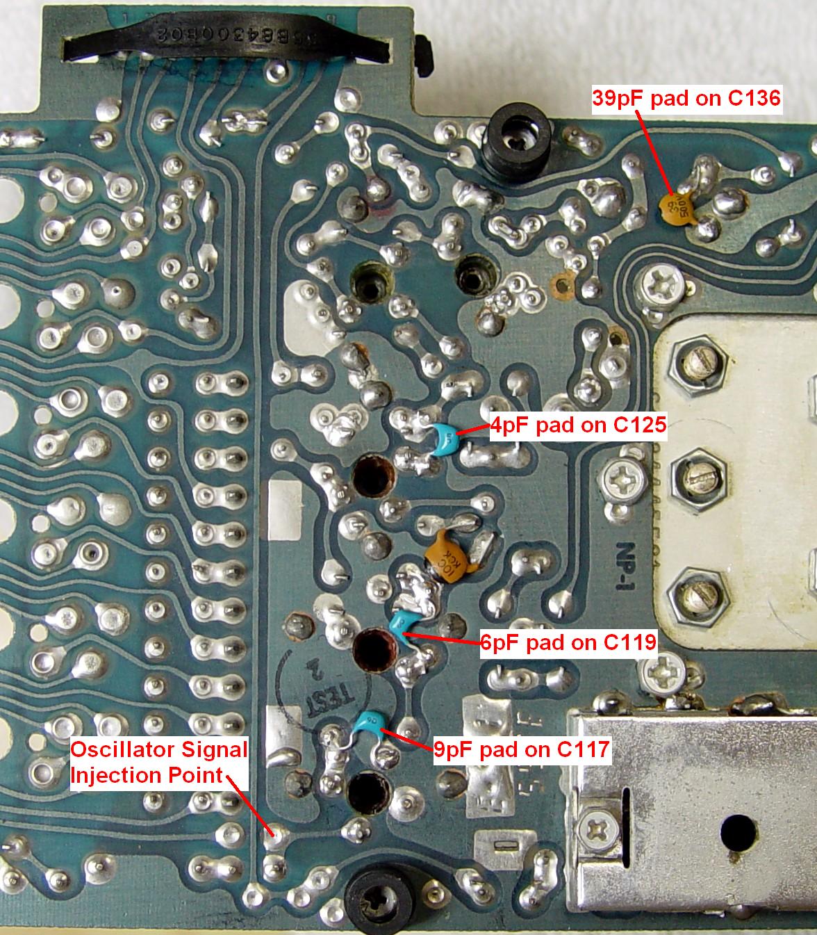
Here's a photo of another board with a 1980 date code on it that I padded. I made sure the capacitor values faced the camera. The board has also been cleaned with alcohol several times. Click on the image for a much larger (300kb) view.
After adding the four capacitors, the affected tuned circuits in the multiplier stages will need to be retuned according to the procedure in the manual, all of which has been retyped here:
| Step | Adjustment | Meter | Stage and Procedure |
|---|---|---|---|
| 1 | L101, L102, L103, L104, L105 | - | Multiplier Coils - Adjust the cores of L101 through L105 to the end of the coil form away from the circuit board. |
| 2 | L106, L107, L108 | - | Injection Filter - Adjust the tuning screws for L106 through L108 until the top of each tuning screw extends approximately 1/8 inch below the receiver shield. |
| 3 | L101, L102 | 1 | Channel Element Output - Alternately tune L101 and L102 CCW two turns at a time until a peak indication on meter 1 is obtained. |
| 4 | L103, L104 | 2 | First Doubler - Tune L103 CCW for a peak reading on meter 2. Tune L104 CCW for a dip on meter 3. |
| 5 | L105, L106 | 3 | Second Doubler - Tune L105 CCW for a peak on meter 3. Tune L104 for a peak on meter 3. Re-peak both coils until no further improvement can be obtained. |
| 6 | L101, L103 | 3 | Detune L101 until meter 3 drops to 10uA. Tune L103 for peak reading on meter 3, keeping this peak below 12uA by further detuning of L101 if necessary. |
| 7 | L101, L102 | 1 | Alternately tune L101 and L102 for peak reading on meter 1 until no further improvement can be obtained. |
| 8 | L106, L107, L108 | 3 | Injection Filter - Tune L106 for a dip on meter 3. Tune L107 for a peak reading on meter 3. Tune L108 for a dip on meter 3. Do not repeat. |
| 9 | L109 | 4, 5 | Discriminator - Insert 11.7 MHz injection probe of the test set into L110 hole on receiver shield. Be careful not to contact the circuit board. Set METER REV switch to position A or B for this step and be sure that the test set is equipped with an 11.7 MHz crystal in the corresponding A or B socket. Insert the injection probe far enough to obtain a saturated reading on meter 5. It should be possible to obtain readings on either side of zero (center) on meter 4 by tuning L109. Tune L109 for an EXACT zero reading on meter 4. This adjustment is critical. [ Author's Note: you can use an accurate signal generator set to 11.7 MHz instead of a test set and crystal. ] |
| 10 | L110, L111, L112, L113, L114, L115, L116 |
4, 5 | RF Preselector and Mixer - Unsquelch the receiver by
turning the SQUELCH control fully counterclockwise. Disable the PL decoder. Connect an
rf signal generator to the receiver input connector and set the rf output of the generator
to maximum. If the receiver frequency has been changed by more than 1 MHz, preset tuning screws L111 through L116 so that the screw end is in the space between the board and its shield, and approximately one-eighth inch from the shield. If the receiver is equipped with the optional preamp, disconnect and bypass the preamp. Set the generator to the carrier frequency by observing meters 4 and 5. If no indication is seen, unscrew the shell of the antenna cable connector, and pull the plug partially out of the jack so that the cable shield no longer makes contact with the station chassis. Set the generator to the carrier frequency as indicated by meter positions 4 and 5, then reconnect the cable shield to the radio. Adjust L111 through L116 clockwise one turn at a time, watching meter 5 for an increase in indication above noise level. Tune L111 through L116 for peak reading on meter 5, reducing generator output level as necessary to keep meter 5 out of saturation. Tune L110 for a peak on meter 5. Repeat the adjustment of L111 through L116. Turn L111 through L116 in or out as necessary until all screws are level. Repeat the adjustment of L111 through L116. |
| 11 | L106, L107, L108 | 6* | Tune L106, L107 and L108 for best noise quieting (minimum meter indication). Maximum meter sensitivity may be obtained by placing the meter multiplier switch on a lower scale. |
| 12 | L111, L112, L113, L114, L115, L116 |
* | Tune L111 through L116 for best noise quieting. Repeat until no further improvement in quieting level can be obtained. |
| 13 | C1, C2, L111 | 5* | Preamplifier - If the receiver is equipped with the optional preamplifier, reconnect the preamplifier. Tune C1 and C2 for maximum meter 5 reading. Then tune C1, C2, and L111 for best noise quieting on the ac voltmeter. |
| 14 | F1 | 4, 5 | ON-FREQUENCY ADJUSTMENT - With a strong, accurate on-frequency signal applied to the antenna, make sure meter 5 moves up-scale. With the AFC test point grounded, adjust the F1 warp capacitor for an exact zero reading on meter 4. |
| 15 | - | Perform 20 dB quieting sensitivity measurement as a check of alignment. The 20 dB quieting level should be less than 0.5 uV (0.25 uV with preamplifier). |
Minimum and typical meter readings for a properly operating receiver, with no input signal, are shown below:
| Position | Minimum | Circuit Metered | Typical |
|---|---|---|---|
| 1 | 15uA | Channel element output | 20uA |
| 2 | 15uA | First Doubler output | 30uA |
| 3 | 15uA | Second Doubler output | 40uA |
| 4+, 4- | 0 +/- 2uA | Discriminator output | 0uA |
| 5 | 10uA | Second i-f amplifier and limiter | 25-35uA |
Receiver Frequency Range:
After modifying the receiver, I used one signal generator as a local oscillator and fed it through a 0.01uF capacitor to the channel element output line, which goes to the tap on L101 at the left side of the schematic. This point is indicated on the photo of the board. The signal amplitude was set to +12.0dBm at a frequency around 54 MHz (three times the channel element crystal frequency). The formula for the carrier frequency (Fc) vs the crystal oscillator frequency (Fo) is:
Fc = (Fo * 24) + 11.7 (all frequencies are in MHz)
The first multiplier stage is tuned to a frequency three times higher than the crystal in the channel element. A crystal frequency of 18 MHz would have a harmonic at 54 MHz and would let the receiver hear a signal on 443.7 MHz.
I used a second signal generator to feed a signal into the RF input of the receiver. I tuned the receiver fully and used the squelch chip to detect the 20dB quieting point by decreasing the input signal level until the squelch burst changed from short to long. (The Spectra TAC receiver chassis audio control module contains the famous MICOR squelch chip.) I recorded the various meter readings and summarized them in the table below. I was unable to tune to a frequency below 430 MHz because the front-end tuning screws ran out of range and thread length. The multiplier and mixer coils still had plenty of range. As you can see, the receiver met its 20dB quieting spec of 0.5uV down to just below 435 MHz.
| Inj. MHz. | Car. MHz. |
M1 uA | M2 uA |
M3 uA | 20dBq dBm | 20dBq uV |
|---|---|---|---|---|---|---|
| 55.2000 | 453.30 | 23 | 34 | 39 | -113.5 | 0.473 |
| 54.6000 | 448.50 | 23 | 33 | 40 | -112.5 | 0.530 |
| 54.1625 | 445.00 | 23 | 32 | 42 | -112.5 | 0.530 |
| 54.0000 | 443.70 | 23 | 32 | 42 | -112.5 | 0.530 |
| 53.4000 | 438.90 | 23 | 30 | 42 | -112.5 | 0.530 |
| 52.8000 | 434.10 | 23 | 29 | 44 | -113.0 | 0.501 |
Equipment Utilized:
Agilent E4430B signal generator (RF signal into receiver)
Fluke 6071A signal generator (crystal oscillator signal)
Spectra TAC chassis with audio control module and PL decoder
Simpson 260 VOM (for metering)
Acknowledgements and Credits:
Information for this page was obtained from the Spectra TAC Voting and Satellite Receivers Instruction Manual, 6881039E45-A.
MICOR, Spectra TAC, PL, and a bunch of other terms are trademarks of Motorola, Inc.
Ron W9FT supplied information about the export model and C136.
Thanks go to Dave N1OFJ for modifying the first UHF receiver board and supplying it for photographic and testing purposes.
Contact:
The author can be contacted at: his-callsign [ at ] comcast [ dot ] net.
This page was created 25-Apr-2007
Go to the top of this page
Back to the MICOR index
Back to the Home page
Article text © Copyright 2007 and date of last update by Robert W. Meister WA1MIK.
This web page, this web site, the information presented in and on its pages and in these modifications and conversions is © Copyrighted 2007 and (date of last update) by Kevin Custer W3KKC and multiple originating authors. All Rights Reserved, including that of paper and web publication elsewhere.