Modification of the Motorola® MICOR Exciter
By Kevin K. Custer W3KKC
Concept:
Remove bias voltage from audio input of MICOR exciter, and ensure proper
keying with removal of PL encoder.
Description:
Most Motorola® MICOR exciters, for mobiles, and some stations,
exhibit a dc voltage intended to run the microphone amplifier that exists
in the microphone. This voltage is not necessary when using an external
audio source, such as a controller, to drive the exciter. The resistor
that provides the dc bias voltage also determines the audio input impedance,
330 ohms in high-band, 560 ohms in UHF Station models. Also, when
the PL encoder is removed the path for keying the exciter is removed.
There is a jumper that straps this keying voltage, and since you may be
uncertain where your exciter may have come from this modification will
ensure proper keying if you are not using the original PL encoder deck.
Benefits:
1. Removes dc bias voltage and raises audio input impedance, and sensitivity. Some repeater controllers cannot drive low impedances very well. Most (not all) op-amp circuits used in the majority of repeater controllers can only drive loads in the 1 K to 2 K ohm range without distortion. Lifting this resistor will drastically raise the input impedance and distortion will not result because of too low of impedance.
2. Some controllers have a large coupling capacitor in the output stage. If the bias is not removed, there could be a period of no audio while the capacitor is charging. This could result in chopped ID's and missed syllables during the first part of the transmission.
3. Proper keying will result when the PL deck is removed.
Modification:
For audio bias removal, remove R401, (R407 some models). This is
560 ohms in UHF Stations, and is 330 ohms in high-band models, both Mobile
or Station.
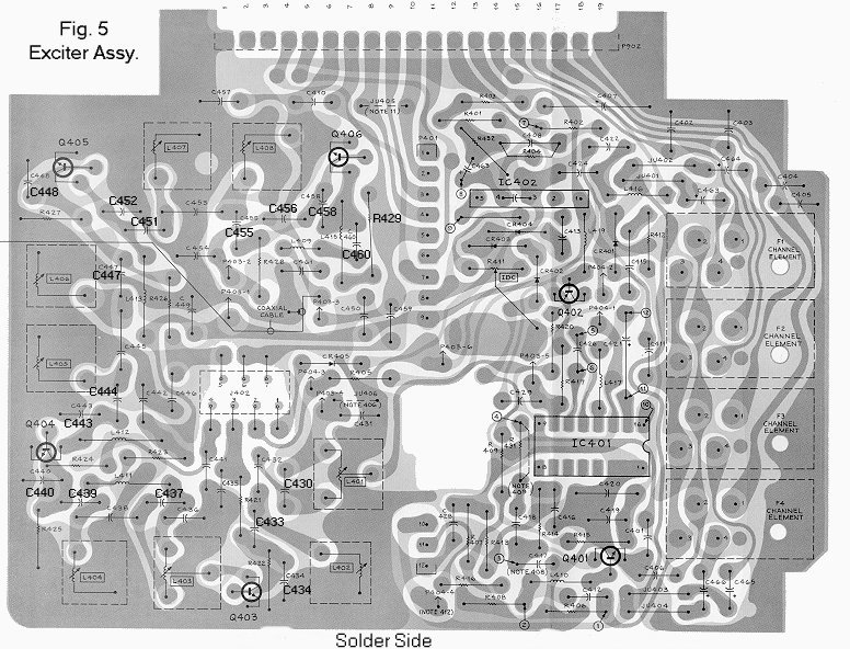
There are two options of modification to allow proper keying of the exciter if you are not using the original PL encode deck. One is, if you never plan on using the MICOR PL encoder, determine that jumper JU405 (JU402 some models) exists between pins 8 and 10 on the long interconnect pins (P902). The second method developed is a semiconductor replacement for the jumper. This is especially handy for those who on occasion determine it necessary to remove the PL encoder board for any reason. In place of the jumper on the exciter board, install a silicon diode like a 1N914 or 1N4148 - being sure of its polarity. With the diode installed, it will make no matter if the PL encoder board is installed or not. The banded end of the diode will go toward P902 pin 8.
Have a high band exciter and don't know where these are? See the image below.
R401 is at the top of the image near the 19 long interconnect pins.
Html Copyright© 1-25-98 Kevin Custer W3KKC
Keying method #2 was submitted by Neil McKie - WA6KLA and was added
to this page on August 12 2001.
All Rights Reserved.