Back to Motorola index
Back to Home
Magnificent Medley of
Miscellaneous MICOR Material
By Mike Morris WA6ILQ
(No, he didn't come up with the title for this page, Bob Meister WA1MIK did)

|
Back to MICOR index Back to Motorola index Back to Home |
This is Mike Morris' Magnificent Medley of Miscellaneous MICOR Material By Mike Morris WA6ILQ (No, he didn't come up with the title for this page, Bob Meister WA1MIK did) |
|
Note: Any Motorola prices mentioned on this page (or on any page at this web site) should be taken only as a rough guideline. Motorola adjusts prices quarterly, and offers one set of prices to their dealers/service shops (the so called "NSO" Pricing ("National Service Organization")), another to "self-maintaining" fleet customers (i.e. those that have their own radio shops... cities, counties, police departments, fire departments, etc) and a third on their telephone order desk (i.e. retail sales). For these reasons readers should use the prices mentioned in an article only as a rough indication. We'd appreciate an emailed update if you discover a major price change.
Additional Information about Useful MICOR Manuals Click here for how to order manuals
Most MICOR manuals are NLA (No Longer Available). All MICOR mobiles use one manual per band - there is a low band manual, a high band manual, a UHF manual, an 800 MHz manual and a 900 MHz manual and they are mostly self contained. All stations (bases and repeaters) use two manuals, one for the RF section and the second for everything else. Instead of duplicating all the pages on the control shelf, power supplies, and other non-frequency sensitive sections in each manual they combined all the non-frequency sensitive sections into a separate manual. Motorola made a separate RF section manual for each frequency range of the MICOR station. If you try to order one of the NLA manuals you will be told that the manual has been canceled or is NLA (same thing).
To work on your base or repeater you will need BOTH the "Control and Applications Manual" AND the appropriate RF manual. If you have a station with the community repeater backplane backplane you will need the appropriate supplement in addition to everything else. Both the Digital Voice Privacy (DVP, or secure) station and the PURC or "Paging Universal Remote Control" station are MICOR-based stations that had different backplanes in the stations and had their own Control and Applications Manuals.
| The Base and Repeater Control and Applications Manual is part number
6881025E60 (non-RF information common to all stations). NLA but it is downloadable. The last version of this manual was Issue F and is here. 12.4 MB PDF scanned by Eric Lemmon WB6FLY. |
|
| Documentation on the TLN5167A Intercom, TLN5900 and TLN5993 Station Metering Kit, and TLN1859 and TLN1887 Metering and Intercom Kits This covers the optional station metering kits and is manual # 6881033E28-F, a 1.64 MB PDF file donated by Eric Lemmon WB6FLY | |
| The low band station RF manual is titled "Compa-Station Base & Repeater Radio 25-50 MHz 100 watts" and is part number 6881013E60 | |
| The high band station RF manual is titled "Compa-Station Base Radio Remote Control 132-174 MHz" and is part number 6881013E65 | |
| The UHF station RF manual is titled "Base and Repeater Station
406-420, 450-470 or 470-512 MHz" and is part number 6881025E50. NLA but downloadable. The last version of this manual was Issue H and is here. 11.1 MB PDF scanned by Eric Lemmon WB6FLY. |
|
| Community Repeater Station Supplement 6881025E55, NLA This is a supplement to the standard Control and Applications manual. You will need this supplement if you have the "Community Repeater" backplane and / or modules. In addition to the different backplane there are several differences between a standard repeater configuration and the community repeater configuration (even if you are going to run only one PL tone, or even in carrier squelch mode). The last version of this manual supplement was Issue B and is here. 5.9 MB PDF scanned by Eric Lemmon WB6FLY. |
|
| The PURC Control and Applications Manual replaces the standard
Control and Applications Manual and is manual 6881060E70. NLA The last version of this manual was Issue B and is here. 13.5 MB PDF scanned by Eric Lemmon WB6FLY. This manual has, among other things, the documentation for the TRN5349A non-unified backplane, the TRN4860A unified backplane, TRN5348 transmitter flat audio module, the TRN4854B Station Control module, the TRN4857A Alarm module and the TLN2559B Simulcast Module. Note that many PURCs did not have a receiver at all - they used a wireline modem as a source of the modulation signal. Some did have a receiver, but they were in a different band (75 MHz was a common range for the point-to-point link frequency) and were configured as crossband repeaters - the paging company would put the primary signal on the link frequency and each paging site transmitter (be it low band, high band, or UHF) would be either a simple crossband repeater or a simulcast crossband repeater. The exciter in a PURC is special and is optimized for data transmission - there is no pre-emphasis circuitry or what would be considered a speech modulator. If you plan on converting a data-line PURC to a voice repeater you will have to add a receiver - I suggest an Auxilary Receiver chassis, or a Spectra Tac chassis configured as an Aux Receiver. Plus, I suggest that you plan from day one to replace the paging exciter with a regular exciter that has internal pre-emphasis. |
|
| We have the DVP Securenet VHF Station Manual is 6881036E40-B below. Does anyone have the part numbers for the Low band or UHF DVP Securenet Station manuals? |
|
| Mobile UHF (standard and wide spaced): 6881015E70 | |
| Mobile high band manual: 6881008E40 Mobile high band wide-spaced supplement: 6881014E15 (see note below) |
|
| Mobile Low Band manual: 6881008E35 | |
| Moto offered multiple PL decode for the MICOR station - just scroll down to the entry for Multiple Tone PL Options - Manual number 6881106E30-B. The actual TLN5745 card is rare but there are a couple of suggestions on home-brewing your own. |
Miscellaneous MICOR Tidbits
The Micor was the probably the pinnacle of carrier squelch development, because it was designed when many agencies needed it for interoperability. Elegant carrier squelches were less important with CTCSS / PL / DPL. Digital modulation modes are making CTCSS / PL / DPL a relic.
MICOR era radios have relatively narrow RF bandwidth. The maximum separation between two transmit frequencies in a standard high band MICOR is spec'd in the manual at 1.5 MHz, however, according to an original MICOR design engineer at Motorola, the exciter is capable of operating 3 MHz wide if it is center tuned 1 MHz above the lowest frequency. The wide-spaced mobile series offered variations with wide-spaced receive, or transmit, or both. The wide-spaced receiver has a second oscillator / multiplier and front end, the wide-spaced transmitter has a second exciter multiplier chain, thus one high band radio can have two1.5 MHz (3 MHz) wide windows separated by up to 12 MHz from each other, and the channel switch selects the appropriate front end or exciter as well as which channel element. The high band wide-spaced supplement is 6881014E15 (note that the main high band mobile manual is 6881008E40 - you will need both manuals for your wide-spaced radio). The wide-spaced manual also has the information on the high-band extender-equipped receivers. The regular UHF mobile manual has both the standard and the wide-spaced info.
Motorola Auxiliary Receivers, Satellite Receivers, MICOR second receivers, and Spectra TAC voting receivers are separate rack mount chassis that holds a standard MICOR receiver board (low band, mid band, high band, UHF, 800 MHz or 900 MHz), plus supporting PC boards in card slots. Information on these can now be found on their own web page. That page also links to an article that has a detailed list of receiver board model numbers and their frequency ranges - if you are trying to find out what frequency range a board is from the part number, look there.
MICOR receiver and audio boards were used in other equipment too. More information can be found on the MSF5000 and PURC page. Look for articles on the PURC5000 link receiver.
I was reminded the other day that a VHF channel element that is 23.4 MHz above where you want to listen (twice the 11.7 MHz IF) will work just fine. For example, a 170.150 MHz element will let you listen on 146.745 MHz and probably will tune to 146.730 MHz or 146.760 MHz as well. Likewise an element made for 467.400 MHz will work just fine on 444.000 MHz. And 472.400 MHz works for 449.000 MHz. It does this because the receiver will work with either low-side injection (where the channel element operates below the desired frequency) or high-side injection (where the channel element operates above the desired frequency).
Very recently, someone was asking about the special screws and speed nuts that are used in MICOR (and other) Compa-Station rack rails, which are unthreaded. It took a while to track down that information, but the good news is that both items are still available from Motorola Parts. The screw is a special, blunt tip Phillips pan head tapping screw, size 1/4-14 and 3/4" long. Its part number is 0300135038, and a pack of 10 screws is about $3. It appears that these screws are stainless steel. The speed nuts, also known as Tinnerman nuts, are 1/4-14BZ, and are part number 0282360B07. A pack of 10 nuts is about $6.
| It is way too easy to break a coil slug while tuning up a receiver or exciter, especially if the slug hasn't been moved in a few years. The MICOR "Universal Tuning Tool" is part number 6684387C01, priced at about $9 (in mid 2009) from Motorola Parts. This handy tool has a thin steel blade on one end that mates with the channel elements and front-end capacitors, and both 0.075" and 0.100" hex drives on the other end for slug-tuned coils. The body of the tuning tool is large enough to get a good grip, making it easy to make very small adjustments. There is one simple mod that makes it more useful: put a little "flag" or "flap" of tape around it so you can count turns when the directions say something like "Start by turning the slug counterclockwise until it is flush with top of the coil form and then turn it clockwise three turns". The flap will also prevent it from rolling off the workbench. | |
| The Motorola Test Set Page There are several test sets that were made specifically for the MICOR station, and others were made for the mobile radios. While this page covers all of the test sets, those interested in MICORs should focus on the TU546 series (the greyface set), the S1056 / 1057 / 1058 / 1059 series, and the R1033 set. If you are going to go out and buy one, the R1033 (and the proper cable) should be your first choice, and the S-series (again with the proper cable) your second choice. Either will work just fine on mobiles and stations. If you are going to look for something to mount in a station cabinet that has no metering then you should look for a TLN1857A / TLN5900A unit as it is self-contained and does not require the meter / speaker panel at the top of the rack. |
Notes:
|
MICOR
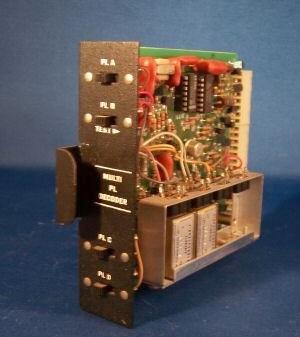
Base Station Accessories - Multiple Tone PL Options - Manual number 6881106E30-B
5.11 MB PDF This manual covers the TLN5746A Matrix Control Module (a tone remote module), the TLN5744A 4-tone PL Encoder Module, the TLN5733AV Converter Board (couples the 4-tone encoder to the transmitter), and the TLN5745A 4-tone PL Decoder Module. The four PL tone decoder module for the standard MICOR station card cage is the TLN5745A Multi-PL Decoder (or TLN5745B). The TRN6166A is the DPL equivalent. When used in the stock repeat shelf, an unmodified TLN5745 (or TRN6166A) card allows the repeater to respond to up to four tones (or codes) on the input, ORed on the card to the single status line that tells the control shelf that a valid tone (or code) has been decoded (i.e. four without the stock decoder in place, adding the stock decoder and a few nonstandard jumpers allows five). With the MICOR station configured as a full duplex base, and cabled to a repeater controller, a modified card can feed four (or five) repeater controller digital inputs and tell it which tone (or code) is being received. The mod consists of adding wiring that picks up the collectors of the four open collector decode lines and routes them to a connector, either a pigtail or a DE-9 punched into the front of the card. One common use of multiple decode is on a club machine, with the first tone (for example, 100 Hz) listed in the local repeater directory, and the second (perhaps 146.2 Hz) used by club members. You would program the repeater controller so that the 100 Hz tone would provide local repeat, and the 146.2 Hz would allow autopatch and other system toys. Installing this card does not preclude any other options as it slides into the otherwise unused tone burst decoder slot. The equivalent PL tone card for the MSR2000 station is the TRN5329, TRN5329A or TRN5329B. Click here for a photo of the MSR version. Except for the edge connector on the card, and the black paint on the bracket, it's identical to the MICOR card. These cards are extremely rare, as they were used in only a few special purpose station configurations. If you can't find one it's not difficult to implement the same functionality by using the stock receiver tone decoder (if there is one) for the first tone, and a separate decoder (TS32 or similar) for each additional tone. You could build a homebrew version of the TLN5745A - I've seen a timeout timer card that someone stripped, cut all the appropriate traces to the edge connector, mounted two TS32s and a piece of perfboard (that had some interfacing logic on it) and slipped it into the tone burst decoder slot. The builder just looked at the TRN5329A schematic and cribbed enough from it to interface a TS-32 to the card cage signals. Two mini-toggle switches mounted in the end plate of the card allowed enabling or disabling each of the two tones. This card was actually more versatile than the TLN5745 as the tones were set with dip switches as opposed to reeds. And there was room for a few more TS-32s if they were needed. One quirk was that the primary decoder (the one internal to the MICOR station) didn't have a squelch tail (because the reed-based decoder supported reverse burst) where the second and third tone (the TS-32s) had a long tail. If one were to built that same card today with Com-Spec's current offering, the TS-64, then you would have one that properly responded to reverse burst. |
|
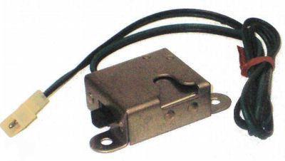
| Documentation on the QLN2812A Station
Identifier Field Modification Kit a 1.2 MB PDF file provided by John Gilbert KA4JMC This kit was made up of a QRN8424B or QRN8425B module, the QKN7547A cable, this documentation and a few other loose pieces. The QRN8424B is used in MICOR stations, the QRN8425B module is used in MSR2000 stations. This module uses a fairly inflexible design - the IDer audio frequency (1200 Hz) is slaved to the IDer Morse code speed. The IDer spacing is either 15 or 30 minutes (but is dependent on the timing of a 555 chip so can be changed). Both of these modules use a 256x4 PROM chip that is almost pure unobtanium (a Monolithic Memories Inc. MM5301-1, some were house numbered with a Motorola part number, some were shipped labeled with the MMI number). Each byte represents one time frame, a dit requires two frames, a dah requires four, a word space requires five. Module overhead uses 31 of the 256 frames. The rest can be used for the actual IDer string (the Morse code sequence). An adapter could be made to allow use of a 27nn or 27nnn series chip, but it's much easier to toss this board into the junk box and use an external repeater controller like an NHRC, Scom, etc... Since the FCC Rules require you to be able to remotely switch the repeater on and off you need a real repeater controller anyway... and you can buy a decent one for under US$160 (the NHRC-4) |
Yes, the UHF MICOR is Part 95 accepted (i.e. legal for GMRS) when 2ppm elements are used.
The UHF transmitter uses a high band exciter (with a part number of TLD5491A (below 150.8 MHz) or TLD5492A (above 150.8 MHz) followed by a tripler, and the tripler is separate from the exciter. If you are looking at the output of the exciter looking for UHF output, you won't see any. This means that if your station was used to transmit below 452.4 MHz that you have the low range exciter (132-150.8 MHz).
The UHF station power amplifier deck needs at least 1.5, preferably 2 watts of on-channel drive (i.e. out of the tripler) to develop full ouput.
The 75w amp draws about 27 amps making full output, the 100w amp needs more. You need a husky continuous duty power supply if you are running a busy repeater.
A fast way to determine of you have a bad exciter or a bad PA deck is to unplug the coax cable from the BNC input connector on the PA deck, and plug in a BNC-to-BNC jumper cable that is plugged into the antenna jack of a 2w handheld that has a BNC jack for the antenna (like an IC4AT). With the station powered up just key down on the HT and see how much power the amplifier deck makes.
The UHF receiver is a TRE120nA or B, and the IF is 11.7 MHz, or 11.8 MHz if needed to avoid mixes or if the customer had two channels exactly 2.925, 3.9, 5.85 or 11.7 MHz apart. Moto offered a kit (TLE8610A) if a receiver needed to be moved from 11.7 to 11.8 MHz in the field.
The TRE1201BA is for 406-420 MHz, the TRE1202BA is 420-450 MHz (very rare), the TRE1203BA is 450-470 MHz, the TRE1204BA is 470-494 MHz and the TRE1205BA is 494-512 MHz.
All UHF receivers used a KXN1024 channel element and a x24 multiplier. The high versus low injection decision was dependent on several parameters.
There was an optional factory preamp (TLE1981A for 406-430 MHz and TLE1982A for 450-512 MHz) that was very common in two-receiver stations. Don't bother trying to find one, get an AngleLinear instead.
The low band and mid band stations use a TRN6007A audio-squelch board and it
is different from the TRN6006A board used in the high band and UHF stations. The
difference is only two capacitors (C210 and C216) and they are easily changed in
the field.
The receiver part numbers (TREnnnn) were not always stamped on the boards, and
some boards were not stamped with any part number at all. This table may resolve
some of the confusion:
| Frequency MHz |
Receiver | RF Deck | RF/IF Board | Exciter/Filter | Tripler/LLA | PA Assembly | |||
|---|---|---|---|---|---|---|---|---|---|
| 12 watts | 20 watts | 40 / 45 watts | 60 / 75 watts | ||||||
| 406-420 | TRE1201BA | TLE8021A | TLE8031A/B | TLE1721B | TLE1601B | TLE1681A | ? | TLE1701A (45w) | TLE1711A (75w) |
| 420-450 | TRE1202BA | ? | ? | ? | ? | ? | ? | ? | ? |
| 450-470 | TRE1203BA | TLE8023A | TLE8032A/B See note |
TLE1723A | TLE1603A | TLE1683A | TLE1693A | TLE1703A (45w) | TLE1713A (75w) |
| 470-494 | TRE1204BA | TLE8024A | TLE1724A | TLE1604A | TLE1684A | TLE1694A | TLE1703A (40w) | TLE1714A (60w) | |
| 494-512 | TRE1205BA | TLE8025A | See note | TLE1725A | TLE1605A | ||||
| 512-530 | ? | ? | TLE8035A/B | ? | ? | ? | ? | ? | ? |
Note: The books that I extracted this information from say that the 8032 receiver covers 450-494 and the 8033 covers 494-512 MHz range. A different book claimed that the 8033 covered 470-494 MHz and the 8034 covered 494-512 MHz. Both books say that the 8035 covers the 512-530 MHz range. Yes, there was a LOT of stuff - both encrypted and clear - up there during the 1984 Olympics in Los Angeles. And that's all I will say about that.
The wide-spaced UHF mobile has both channel select and repeat-offset on/off lines. A common modification on these radios in amateur use is to take the repeat offset on/off line and connect it to a spare lead in the cable rather than into the channel element selecting diode matrix. A mini-toggle switch is frequently installed in the control head just for repeat / simplex selection. The Syntor series of radios (they can be thought of as synthesized MICORs) had a optional faceplate for the clamshell head that was made just for this purpose (the switch is labeled "R" and "S"). This faceplate will fit the MICOR head perfectly.
A second common modification is to rectify one design oversight in the MICOR "clamshell" control head: there is no receiver PL control switch - a "Monitor" switch, if you will. The MICOR mobile was designed as a carrier squelch radio with PL as an option. The designer expected you to use a microphone clip with a built in switch (see the photos on this page. With the microphone in the clip the PL was on, out of the clip you are in carrier squelch (monitor) mode. A later model hangup box had a PL / Monitor switch on it - see this photo.
One solution to this problem is to cut the trace on the control head PC board between J1101 pins 4 and 15 (not easy to do, but can be done with patient work with an X-Acto knife after using solder-wick to remove the excess solder) and jumper the cut with a SPST toggle switch. This new switch when shorted will enable the PL decoder (by cutting the trace and bridging the cut with the switch it is placed in series with the microswitch in the hang-up box).
Contact Information:
The author can be contacted at: his-callsign // at // repeater-builder // dot // com.
Back to the top of the page
Back to MICOR index
Back to Motorola index
Back to Home
This information was moved from the main MICOR Index page 31-Oct-2011.
This web page, this web site, the information presented in and on its pages and in these modifications and conversions is © Copyrighted 1995 and (date of last update) by Kevin Custer W3KKC and multiple originating authors. All Rights Reserved, including that of paper and web publication elsewhere.