By Kevin Custer W3KKC
Concept: The following instructions are provided to help convert a Motorola MICOR Railroad Mobile to a repeater station.
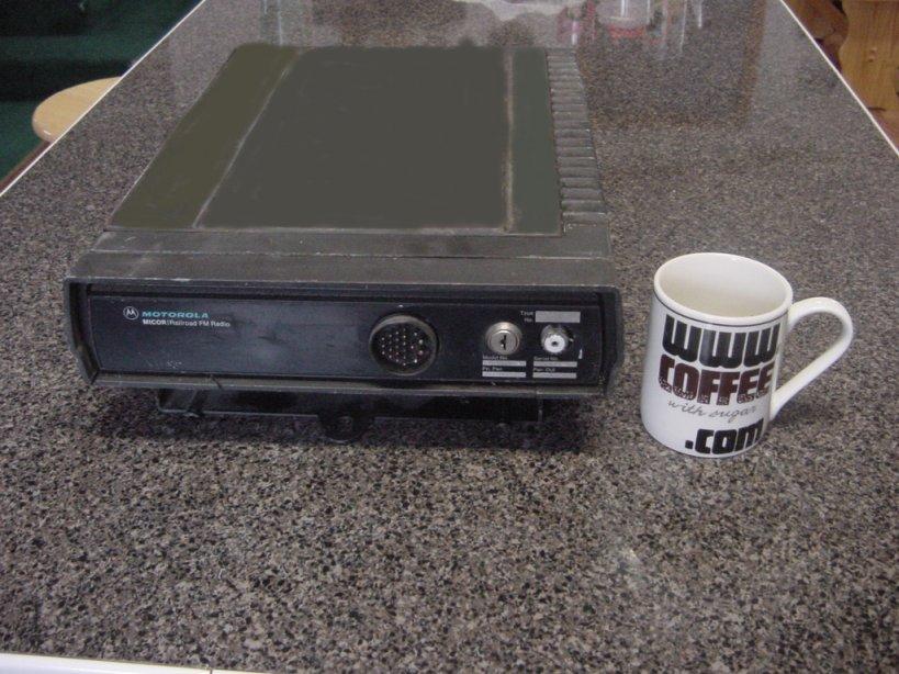
Explanation of the Railroad MICOR Mobile: The "Railroad" MICOR mobile was designed by Motorola to be the ultimate in locomotive railroad communications. The Railroad MICOR was designed to operate from 13.6 or 72 VDC. The radio sets were designed to operate in the 150.8 to 174 MHz. range, with 45 watts of transmitter power, and 10 watts of audio output. Most radios were configured carrier squelch, however PL models were available. The receiver preamp was an available option, however it was located above the control board between the exciter and receiver. Most of the radio resembles the all familiar MICOR mobile, with the exception of the added height of the power supply casting, added power supply circuit boards (4), and the interconnect / control board. The railroad MICOR's interconnect / control board has the volume and squelch pots right on the board, a transistor COS buffer, and a discriminator buffer amplifier (how convenient.) Here's a photo of the railroad MICOR (click on it for a larger view).
Conversion: Start by disassembling the radio set by removing the control head and outer covers to expose the power supply boards. Remove all power supply boards and discard. If the optional plug-in time-out timer is installed, remove it and discard. If the optional 8 channel deck is installed, remove it and discard. This makes lots of room for the addition of optional equipment, like a controller, the MICOR Muteboard, or other user designed circuit boards. There will also be enough room for a receive preamp, if the radio does not already have one. If you cannot locate a genuine MICOR hi-band preamp, the Ramsey PR-10, two meter preamp kit, makes a good replacement. I am not fond of most Ramsey kits as I feel most are poorly designed, and are not of good value, however this cheap preamp kit is a good value. If you have a genuine MICOR Preamp, and you would like it to tune the ham band properly, click on MICOR preamp.
There is a heavy red and black wire coming from the connector that mates with the power supply's "hi-end regulator board", going to the amplifier feedthrough caps. Cut the leads at the connector, keeping them as long as possible. The main B+ and ground connection will be connected to these leads, to the power amp feedthroughs. Power to other circuits will be connected directly to the amplifiers feedthroughs. Wire a large electrolytic capacitor across the feedthrough capacitors on the power amplifier, observing polarity. something around 1 to 5 thousand uF @ 35 to 50 volts dc. Double sided foam tape can be used to secure the filter capacitor. A barrier terminal strip, located on the outside of the cabinet or front panel, may be used to terminate the heavy supply leads, and allow easy connection. An 8 position terminal strip can be used to terminate all signals that will leave or enter the radio.
Power now needs to be connected to the interconnect / control board. There is a small red lead, (wire # 5) located on the control board, near the 3 pins of the "power set control" board. Connect this lead to the large red lead on the amplifier feedthrough. There is a small black lead, (wire # 2) near the "netting switch". Connect this lead directly to the large black lead on the amplifiers feedthrough capacitor. This supplies filtered power to the control board.
To energize the receiver at all times, jumper transistor Q905 emitter to collector on the interconnect / control board. The transistor does not need to be removed. Also, cut out CR922, and CR914 on the control board. The removal of these diodes inhibits the receiver mute, and transmitter delay PTT. Also the removal of CR918 will disable the PL on & off function. Since you are making a repeater, and will probably use a repeater controller to manage the repeater access mode, simply remove CR918.
To enable the F1 channel element position, on both the receiver and exciter, ground the cathodes (banded end) of CR908 and CR904. Since you are making a repeater, and only one set of channel elements will be used, the cathodes of all channel element enable diodes may be connected to ground, to allow ONE channel element to be placed into ANY open position of either the receiver or exciter. If you enabled all positions, do not put more than one channel element into either the receiver or exciter, because both elements will create signals and strange things will happen!
Modify the exciter as described in Motorola MICOR exciter conversion. Also, be certain to place a jumper (JU405, on TLD5382A exciter) or (JU402, on TLD5282A exciter) from pin 8 to pin 10 on the exciter interconnect pins, (P902). This routes keyed A+ to coil of the PTT reed switch, and applies keyed A- to the exciter. Crystals for the transmit channel element (K1007), for the ham band, can be purchased from Bomar Crystal. Tune the exciter per the Motorola manual. No component changes are necessary to the exciters named above for use in the 2 meter ham band. The power amplifier will also tune and have good efficiency in the ham band. The bandpass filter that exists between the exciter, and power amplifier may be taken apart, and retuned to the ham band; remember the filter changes tuning when placed back into the case, so tune and test, then repeat if necessary.
Modify the receiver "RF & IF board", (TLD5273A and B) & (TLD8273A and B) as described in Conversion of MICOR Sensitron Hi-band Receiver.
Modify the receiver "audio & squelch board" as suggested in the Motorola MICOR mobile audio & squelch modification.
An antenna connection can be made from the receiver, or preamplifier to the front panel. An SO-239 style UHF, or BNC connector can be fashioned onto the front panel, in any convenient manner. If an SO-239 is used, also use a "hood" on the back of the connector to totally shield the pin of the connector. If a front panel connection is considered, be certain not to disrupt the cover locking mechanism.
The transmit antenna connection can be made through the original antenna connection. Consider disabling the antenna relay as described in the Motorola MICOR mobile antenna switch modification.
Refer to the manual for connections to the P901 interconnect
/ control board pins, for COS (squelch indication), Mic audio, Speaker
or 8 ohm dummy load, PTT, Discriminator audio. These signals can be routed
to the barrier terminal strip on the outside of the cabinet or front panel.
Be certain to have either a speaker, or 8 ohm five to ten watt load resistor
connected to the speaker terminals as the audio output stage will oscillate
with no load. If you are using something else than the radio to monitor
receiver audio then consider removing the Audio Output Transistor assembly,
as it will conserve power, and won't oscillate. Also remember to
install a PTT disable switch in a convenient place, like on the front panel.
This switch can be a simple SPST toggle, and can be inserted in series
with the PTT lead from the controller. If you need PL filtered, and/or
squelch gated audio for your controller, consider using the
MICOR Muteboard
for developing the receiver audio.
January 30 1998 Kevin K. Custer W3KKC e-mail me with comments.