Back to Home page
for Better IF Performance
Original procedure by John Haserick W1GPO
Published by Robert W. Meister WA1MIK

|
Back to MICOR index Back to Home page |
Combining Two MICOR Receivers for Better IF Performance Original procedure by John Haserick W1GPO Published by Robert W. Meister WA1MIK |
|
Background:
The VHF low-band receivers use ordinary broadly tuned coils in the front end. They rely solely on the crystal filters in the Intermediate Frequency (IF) section of the receiver to determine channel selectivity and bandwidth. Five crystals provide 10 poles of filtering, but the front end is still rather broad, especially when compared to the helical front end in the VHF high-band receivers.
When compared to the low-band Syntor X receiver, the stock low-band MICOR receiver with the bullet-shaped IF response had more 12dB SINAD distortion at 5 kHz deviation. It seemed that the MICOR needed more adjacent channel rejection, but had better audio recovery at low voice deviation in the noise than the Syntor X. In addition, for less repeater throughput distortion at 5 kHz deviation, we set the transmitter's deviation limiter above 5 kHz peak limiting and at the same time limited the repeater audio deviation to close to 5 kHz. Now the receiver pass-band cuts out excessive repeater deviation with no audio compression, as the deviation limiter would have started to compress audio at about 10% of peak (or 4.5 kHz peak deviation if set at 5 kHz peak limiting as per Motorola).
John came up with a nifty solution: he wired two receivers up in series. The first receiver connects to the antenna and has the front end, oscillator, mixer, and IF stages intact. The output from the third IF amplifier is fed into a second receiver's IF input. Signal detection is performed by the second receiver's discriminator stage. This creates a receiver with two 10-pole crystal filters and tons of IF gain and limiting. The major advantage of the dual MICOR configuration is increased adjacent channel rejection, with somewhat improved speech recovery in noise as a side benefit.
For the first (input) receiver, John converted a 72 MHz (mid-band) MICOR receiver strip to receive 50-54 MHz by swapping the front-end and oscillator coils and capacitors from another 50-54 MHz strip. The IF output from this re-banded receiver feeds the IF input of a stock 50-54 MHz receiver strip, using just its IF and discriminator sections, to come up with a super-tight receiver with 20 poles of crystal filtering. Here's a block diagram showing the complete arrangement. Click on any diagram for a larger view.
Initial Testing and Alignment:
Before conversion, each receiver needs a performance check for sensitivity. IF response should be checked for symmetry and the discriminator should not deflect from zero when white noise is added to the receiver input as compared to a 50-ohm dummy load. An antenna near a sparking motor is one noise test. On the average, one in five analog MICOR receivers can be given excellent alignment. The best way to check alignment is with a sweep generator, so you can tell if an imbalance is in the IF or discriminator. If the IF is not symmetrical, you might want to look for another receiver strip. Usually if the IF is symmetrical and the discriminator is out of balance, all the discriminator needs is a slight reduction of the value of the higher-valued balancing resistor (R125) from 27K to 22K, so that a very strong +5 kHz signal gives the same meter deflection or reading as an equal strength signal at -5 kHz on meter position 4. You can add a high value resistor (100K-300K) across R125 to achieve balance.
Figuring Out What You Have:
In this article, "digital" means the receiver has a flatter IF response and a few component differences that make it more suitable for digital (i.e. binary) data streams, while "analog" would be the ordinary voice receiver used in mobile or base/repeater stations.
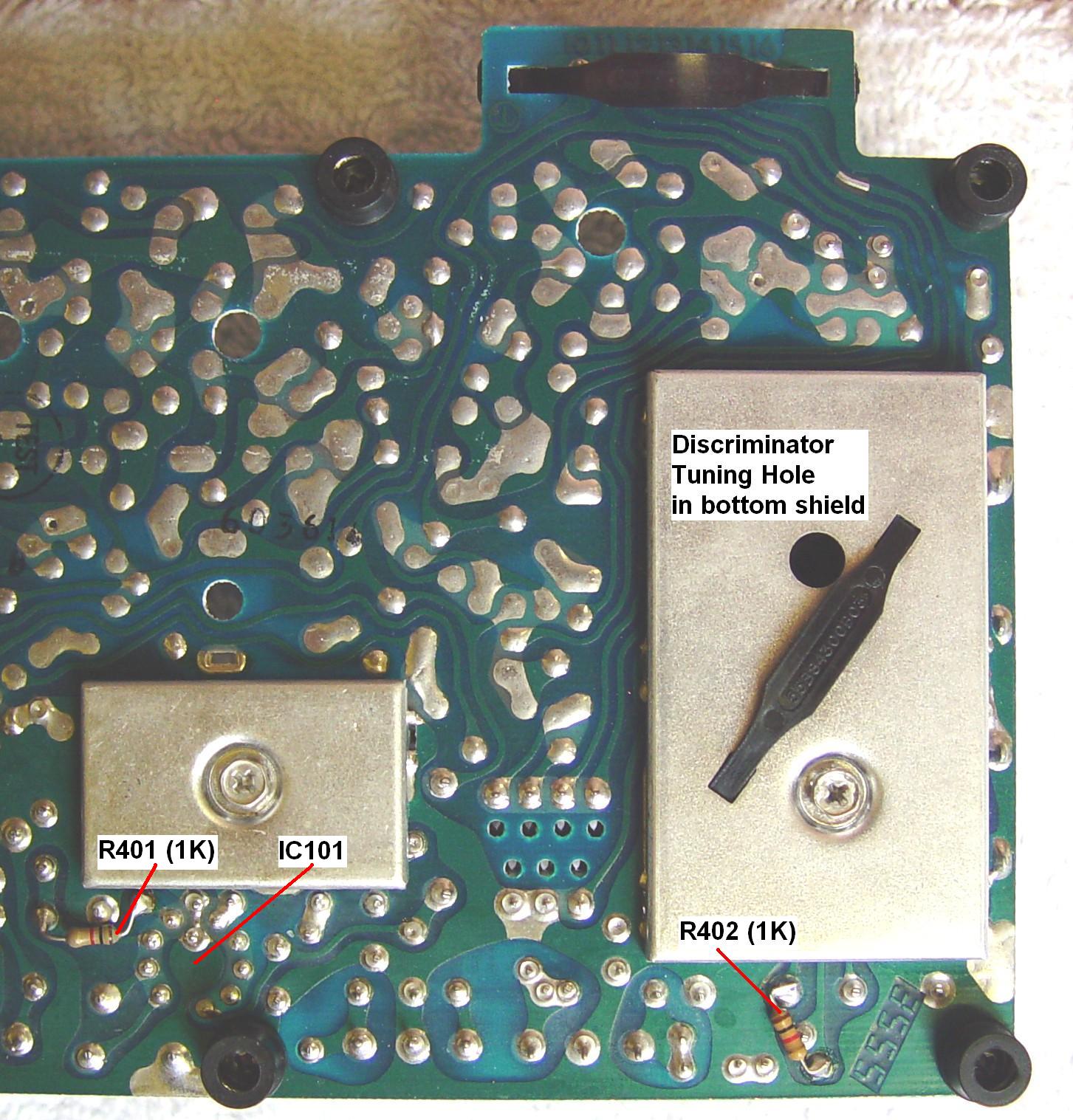
The first receiver needs to be digital (made after 2/86). These were typically used as link receivers in paging systems; 72 MHz (mid-band) seems to be common. The digital schematic should show R401 and R402 (1K), which are installed on the solder-side of the receiver near IC101 and IC102. Note that these parts are NOT in the parts list and are not present on the older analog low-band MICOR receiver strips or schematic. If the first receiver is analog, the combined band-pass will be too narrow.
The part numbers on the tops of the crystal filters along the edge of the receiver strip will be 84259B07, 8, or 9 for the digital ones and 84259B01, 2, or 3 for the analog ones. You may also see "KFN" numbers and date codes on the sides of these filters.
Besides the crystal filters, another 18 parts values are optimized for broader, flatter IF response to support the digital modulation schemes used for paging systems.
Converting Mid-band to Low-band:
John took parts from a 42-50 MHz strip and installed them in the mid-band strip to end up with a 50-54 MHz receiver. It turns out that the injection amplifier coils L101, L102, L103, and L104 are the same in mid-band and low-band 42-50 MHz; it's just the front-end coils that need changing. It turns out that all but one cap (C122) needs to be changed to convert from mid-band to 50-54 MHz; all others are perfect for 50-54 MHz and will give a narrower band-bass than converting a 42-50 MHz receiver to 50-54 MHz by published methods, without loss of sensitivity. He actually went further and under-coupled the coils with 0.51 pF coupling capacitors and changed L109 to the same configuration as L105, L106, L107, and L108 (7-1/2 turns instead of 10-1/2 turns) and therefore had to use 15 pF instead of 3.3 pF across this last coil before the mixer. Converting the mid-band injection amplifier circuit to 50-54 MHz requires eight capacitor changes and four resistor changes (capacitor values are pF, resistor values are ohms):
This receiver is completely tuned per the instruction manual. This receiver has the channel element to determine the received frequency. For VHF low-band receivers, the crystal frequency formula (standard low-side injection) is:
Fcarrier = (Fcrystal times 3) plus 5.26 MHz.
To compensate for these component changes, an external pre-amplifier was added to bring the receiver sensitivity down to 0.15 uV for 12 dB SINAD. Critical coupling is about 0.62 pF if 18 pF is resonating the coils on 6 meters. The five under-coupled front-end coils now tune sharply with four 0.51 pF coupling caps. The net gain of the preamp is about 6dB, just enough to lower the noise figure of the receiver to as low as it can get with an ARR GaAsFET preamp and no more gain than is needed to accomplish that goal. Any more than 6 dB overall gain (16dB preamp gain minus 10dB pad attenuation) just degrades the receiver's inter-modulation and spurious response specifications without improving desired signal reception or noise level.
First Receiver IF Modifications:
Remove (or unsolder one end of) L127 (100 uH) to remove power from the third IF amplifier (IC102). Insert a 51-ohm resistor between R402 and C154 (0.1 uF). The center conductor of a piece of 50-ohm RG174-size coax is connected to the junction of the 51-ohm resistor and R402, grounding the shield to chassis ground. The other end goes to a new BNC-female connector placed on the rear of the receiver enclosure (by the big motherboard for the repeater). John used a piece of Teflon coax from a junk MICOR mobile radio as it won't melt or deform when being soldered.
The IF output BNC of the first receiver is connected to the regular BNC antenna input of the second receiver with a short coaxial jumper cable.
Second Receiver IF Modifications:
The second receiver should be analog for best voice traffic reception. The antenna input coax inside the chassis becomes an IF input and is rerouted to the mixer circuit area. (You could install a second BNC jack on the second receiver if you don't want to repurpose the antenna jack and cable.) Disable the injection amplifier circuit by removing (or unsoldering one end of) L121. The mixer circuitry is under a shield can, which must be removed, requiring a bottom shield to be removed first. The mixer is then disabled by removing Q102 and C130. In place of C130, place 2 caps in series: 160 pF plus 750 pF to ground. The coax center lead goes to this connection between the caps, across the 750 pF cap to ground. John actually unsoldered the antenna RCA jack connector from the circuit board and installed it in the mixer area; this allows you to re-use the antenna coax lead already in the chassis. Detected (discriminator) audio comes from this receiver. The standard MICOR squelch and PL/DPL decoders all utilize this raw discriminator signal.
Additional Information:
X-ray views of the IF and Discriminator area of a 72 MHz "digital" receiver as well as the Front End and IF area of a 50 MHz "analog" receiver can be found in this 3.8 MB PDF file. Neither R401 nor R402 is shown in these views but are pointed out in the photo below, supplied by WA1MIK.
IF Bandpass Spectrums and Performance Analysis:
Bob supplied a stock digital mid-band receiver strip and John supplied a stock analog low-band receiver strip. We swept the IF section of both receivers by loosely coupling a 5.26 MHz signal into the mixer output coil. We probed the output of the 3rd IF amplifier at IC102 pin 8, noted as point "E" in the schematics, with a high-impedance probe. The spectrum analyzer was tuned to 5.26 MHz and the span is 50 kHz, so each horizontal division represents 5 kHz. The two IF band-pass traces were overlaid and saved as one image shown below:
While the colors are hard to differentiate, the blue trace is from the digital receiver that has a flatter, broader top with steeper sides. Both receivers have about +/- 10 kHz bandwidth at 40dB below the peak signal level.
We then swapped the analog low-band receiver strip for one modified for external IF input, while Bob modified his digital mid-band receiver strip to provide an IF output. Also, John disabled the 1st IF amplifier (Q103) in the low-band receiver by unsoldering one end of R111. This reduced the gain of the receivers and lowered the noise floor. The IF output of the digital receiver was connected to the IF input of the analog receiver per the instructions in the article above. We then fed the 5.26 MHz signal into the digital mid-band strip and probed the analog low-band strip as above. This is shown in the image below, which represents the result of the two receivers connected in series.
In this configuration, the system has about +/- 10 kHz bandwidth at 70dB below the peak signal level, which is quite an improvement.
Acknowledgements and Credits:
Schematics and X-ray views for the low-band (50 MHz) "analog" receiver came from the Motorola Spectra TAC Receiver Instruction manual, p/n 6881039E45. Schematics and X-ray views for the mid-band (72 MHz) "digital" receiver came from the PURC5000 Link Receiver Options manual, p/n 6881064E10.
MICOR, Syntor X, Spectra TAC, PURC5000, PL, DPL, and a whole bunch of other terms are trademarks or copyrights of Motorola, Inc.
Photos were taken by Bob WA1MIK.
Contact Information:
John can be contacted at: jhaserick84 [ at ] comcast [ dot ] net.
Bob can be contacted at: his-callsign [ at ] comcast [ dot ] net.
This page was created 29-Jul-2014.
Go to the top of this page
Go back to the MICOR index
Go back to the Home page
Article text © Copyright 2014 and date of last update by John Haserick W1GPO and Robert W. Meister WA1MIK.
This web page, this web site, the information presented in and on its pages and in these modifications and conversions is © Copyrighted 2007 and (date of last update) by Kevin Custer W3KKC and multiple originating authors. All Rights Reserved, including that of paper and web publication elsewhere.