Synthesized MICOR Station Modification
By Greg
Carttar (ex-WAØLCZ)
3rd St. R & D Production Services
Don't want to do this yourself? We'll do it for you.
Email us.
Revision 03/12/14
Check out the communications system we provided to The Defense Advanced Research Projects Agency for the DARPA Grand Challenge Robot Race
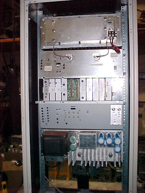
Finished MICOR Station modification on a C64RXB3106
( 75 Watt UHF, DVP Transparent, tone remote control, voting )
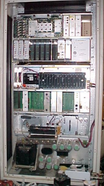
Nearly finished MICOR Station modification on a C73RTB3106DT
( 110 Watt VHF intermittent duty, Non-DVP, PL, tone remote control, voting )
Built from a re-jumpered C73RTB3106E VHF Base Station
This photo also shows a 3-channel voting comparator and one
UHF link receiver
This project began as an experiment to come up with a frequency-agile station to back up several repeaters which are installed in a truck that we use on our special event communications projects.
We purchased a complete metropolitan-scale UHF system from Salt Lake City which included a number of B64RXB3106 (75W, Upright, DVP transparent, tone remote control) repeaters. These repeaters were also configured for voting repeater operation. Originally, we were going to part out the MICORS, but the more we got to know them, the more we fell in love with them. We then bought the voted DVP stations from Honolulu PD. We love these old dogs. We've got 18 in use now, and we want more.
And, we are MICOR purists. We feel that these stations are some of the most reliable and bulletproof machines in the world today. (20 years from now, try to get parts for an MTR2000......I don't think so). They are serviceable to this day.
It turned into a really good working upgrade for our stations.
How Motorola did it in those days......
One of the repeaters in the system was configured as a switchable multi-channel unit which backed up the others. It had an SP modification which added an additional sub-chassis that contained multiple channel elements, some buffers, and a switching harness. An audio patch bay was provided that would allow the agency to sub out any receiver, transmitter, or whole repeater which failed, quickly.
We considered modifying the other stations for similar operation.
Too many channel elements
Unfortunately, our licenses in sites and cities we go to do not always allow us to use the same set of frequencies. We were faced with having to have a huge selection of channel elements to accommodate a wide variety of licenses; and a pretty massive amount of re-alignment at different event sites. (The MICOR only provides an 800kHz range between lowest and highest frequency without re-alignment).
In disaster restoration, who knows what frequencies we'll need to cover.
I contacted several engineer/consultants regarding the custom design of synthesized exciters and receivers, or the possibility of replacing channel elements with some sort of synthesizer. It just got more and more problematic (and expensive) , since we needed to retain PL (tone squelch) capability and actually wanted to add DPL capability. We also did not want to eliminate entirely the potential capability of doing DVP.
DVP requires direct FM modulation and switching of PL circuitry in and out since DVP is incompatible with any coded squelch.
In the final analysis, it all came down to frequency stability, reliability, and reversibility (what if it didn't work and we had to put them back?)
We needed commercial stability, commercial modulation control, and for all its mysterious modules and myriad signal routings on the backplane, the MICOR station is incredibly flexible, adaptable, and reliable.
Last but certainly not least, we weren't ready to spend $20,000+ each on Quantars (no matter how much we'd love to).
This modification project is not for the faint-hearted or those who cannot read schematics and trace signal flows, or for those who refuse to use the manual. Don't take this on if you do not have the books. This mod is not a way to resurrect a corpse that does not work. It is rather a mod to modernize a venerable, tough, and reliable machine.
No offer of support or elmering is expressed or implied unless we build a station for you.
These modified machines are rock solid, stable, and the RF is as pure as the driven snow.
Your machine has to work in stock configuration before you modify it.
We looked at a lot of options. We considered using SyntorX9000 front ends. We looked at several portables including MT1000's (see below). We considered Maxtrac or Radius Mobile synthesizers.
We decided to use Motorola HT50/P100 portables as exciters and receivers. They are synthesized, are capable of both PL and DPL encode and decode, already have good audio processing and deviation limiting, and provide a direct VCO modulation path. The VCO deviation is programmable. They have excellent transmit spectral purity. The receivers are real hot (typically .2 usable or better) and although they require some additional front end filtering (more on that later) they are pretty stable. They are capable of 12.5kHz channel spacings and have commercial frequency stability.
We specifically settled on the HT50/P100 radio because it runs on 10 volts and the station provides up to 3 amps of 9.6 volts (the 9.6 supply is fused at 4 amps). This is a tough, reliable little radio with a cast aluminum structure which is the heatsink and supports the board assembly, and is from the time when everything in the Motorola line was tough and well built. The HT50/P100 radio has selectable power out, either 1 watt or 4 watts; although there is a low-power model which is 1-watt out. They are either 2 channel or 6 channel and the channel select switch is very simple and easy to hack into, as is the transmit power control switch. On the low power setting, the UHF radio will key-up for hours at a stretch without warming up to any significant degree, although the VHF radio final gets a little warm. With a little bit of additional heat-sinking (more on that later) it will run at full power for hours as well.
The chassis of the radio is fully accessible when removed from the case, and the screw-on antenna can easily be replaced with a BNC connector.
The radio is not so highly integrated that it is impossible to get to important points in the circuitry.
We have experimented with using MT1000's instead, since they also run on 10 volts, and have played with integrating the circuitry of an enhanced display MVA...... but that's another article. They are more integrated and a little tougher to deal with.
It is at least theoretically possible to consider doing this mod with Maxtrac or Radius Mobile decks, but we have not tried it.
We had lots of P100's to sacrifice, but didn't want to take any mobiles out of service.
I suppose that you could use any brand of portable you want, provided that it puts out no more than 1 watt to drive the power amp, and provided that you can get PL detect or COR from the receive radio.
So What You're Really Doing Is.......
So basically what we're doing from the RF standpoint is putting a power amp on a portable for the transmit side, and an external antenna on a portable with additional front end filtering for the receive side; and tying them into the signal processing circuitry in the station chassis.
We're eliminating the exciter, channel element, IPA, and tripler in the UHF transmitter, the exciter in the VHF transmitter; and the whole receive deck in the receiver. We're keeping the excellent squelch operation of the MICOR audio/squelch board, but using COR/PL detect from the portable receiver.
With this modification, we have preserved all the functionality (voting, tone control, failure revert, PA protection, isolation, wireline interface, robust mechanical integration, other options) and flexibility of the MICOR station and the modification is 100% reversible back to original condition if you wish to.
In use, receiver re-alignment is reduced to simply peaking up the front end filter, and there is no transmitter re-alignment. Just re-zap the programming of the receiver and exciter and go.
In our application using 6-channel radios, we have a high probability of being able to set up channels so that a new site simply involves changing channels and peaking the helical filter and the transmit combiner.
In a ham application, this is an easy way to back up multiple machines at the same site, provided that all the frequencies are within 800kHz or so (max channel spacing for the helical front end). In a ham application, there will be some alignment of the portable to get it down into the ham bands. I know that a P200/HT600 and an MT1000 will go down there, but I have not tried it with a P100/HT50.
Make no mistake....you are still going to have to have real good cavities for 2-meter operation at 600kHz offsets.
This Article
This article is specifically aimed at those who wish to upgrade a stock MICOR repeater with synthesized exciters and receivers. We cannot be of help on a stripped machine. Kevin Custer's repeater-builder website is the best place to get information on using stripped machines, and is the ultimate reference for same.
This modification article deals specifically with the B or C64RCB3106 unified chassis. (Upright or Compa, 75W, UHF, tone control station. It can also apply to a RXB (Securenet), but there are a couple of the DVP modules you will have to either bypass or leave in. (If you have an RXB, we'll swap you.) It does not deal with a CR Station, you are on your own there.
The basic unified chassis for a repeater is the same for VHF, UHF, and 800.
This mod can also be used with a 30 watt station, which has one of two power amp configurations, either a separate power amp with fewer power blocks in it, OR an intermittent duty PA which is mounted in the unified chassis.
We have not done this conversion to a non-unified chassis nor have we explored it; but this is basically about the RF sections so it should not be too much different.
As of this writing, we are doing a mod to a VHF station, and it's pretty painless so far. The one we're doing is an intermittent duty, unified chassis. You can tell an intermittent duty VHF repeater because it looks like it has the butt end of a mobile sticking out of the chassis. (It does) The included photos of the VHF mod are rough, because we haven't finished it yet, it's still burning in. Works great though.
As I said earlier, If you are going to leave the stock modules in your station, get a companion applications manual. Bite the bullet and buy the books. Kevin Custer recommends stripping all the modules except the station control module. If you are ever going to consider voting your station, leave the stock modules in (squelch gate, station control, line driver). The voting encoder module will drop in with very little grief and very little external stuff. However, if you have a community repeater model MICOR, forget about voting it. You can do it, but it's a pain.
If you decide to vote your repeater, you will want the squelch gate so that the station will revert to ICR (In cabinet repeat) in the event of a comparator failure. Also, if you vote it and your comparator is remotely located, you will want to keep your guard tone and f1/PL modules so the comparator can control the station with tones. Find a 4-wire line driver module (it does not have to be a Spectra TAC Line Driver)
Lastly, if you want to make a repeater "channel agile" for backup, you may want to hunt up some wild card or 4-frequency control modules and you'll need the F1/PL module to go with them.
Regarding Reverse Burst, squelch
behavior, and squelch gates -
I prefer to use the stations in stock configuration, because we only use Motorola
portables and mobiles which generate proper reverse burst to eliminate squelch tails.
Don't get me started on Maxon, Kenwood, Vertex, etc.; but they don't generate
reverse burst. My event clients will not hear of using them.
I like squelch gates, when a station has a squelch gate, it will make it possible to enable the stock repeater configuration, and I don't find them that difficult to set up. I'm not challenging anyone's views on this, but this is my purpose and hence the reason for the way my mod is done. Since we run voting systems, we need the ability for the station to recover from a failure of the voting comparator or the audio links. The squelch gate provides that capability. More on this below.
This mod will generate reverse burst on transmit if you are using PL, and there is no way to defeat it unless you use non-Motorola exciter radios.
To each his own. :-)
External Ham Controllers and Kevin Custer's Mods
If, however, you want to use an external ham controller, stick with Kevin's directions about the modules. If you pull all your modules, Call or email us...we want them. Kevin's mod should not have any effect on the RF aspects of our mod, except that we use the channel element ground signal to key the exciter, so you want the variation that does not lock the channel element on. In our version, if the exciter keys, it's gonna transmit.
Do the RF part, ignore all the modules and signal flow part.