Revision 03/12/14
On one end of the helical filter, there is a removeable cover which conceals the mixer PC board. Remove the cover and the two threaded stand-offs which hold the mixer PC board. Keep the standoffs. Carefully unsolder two wires which go to the mixer PC board, and remove the PC Board. One comes through the casting underneath the board. Here's where you make a decision as to whether to keep the modification reversible or not.
If yes, take the wire which came up to the bottom of the board and solder it down to the casting to terminate it. If no, cut it off flush with the casting. The wire which comes from the last preselector cavity will connect to the coax shown in the picture above.
After removing the mixer, re-install the standoffs.
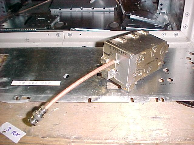
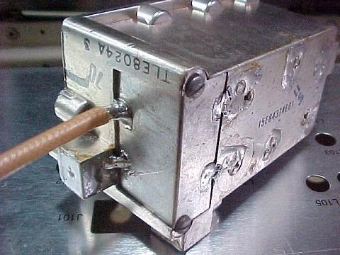
Take your RG142 male BNC to bare end jumper and prep the bare end so that about 1/4" of shield is exposed along with about 1" of center conductor. Tin the shield. Take the little cover that came off of the mixer housing and tin around the little slot. Work the tinned shield into the slot and solder the shield to the cover. Strip about 1/8" of insulation from the center conductor. Install the cover with the coax back on the end of the helical filter, after soldering the center conductor to the end of the wire which comes out of the casting from the 6th cavity. Carefully seat the cover and screw it down with the original screws. As you re-assemble it, watch to make sure that the solder splice doesn't short out against the casting or break as you put it together. When you have successfully re-assembled it, put a couple of solder bridges to the cover from the casting.
The coax braid has to have a very good mechanical solder connection. Teflon coax is highly recommended to resist the heat of making this solder joint.
The mixer cavity slugs have been removed, they are no longer needed.
The standard station antenna cable will plug into the filter just like it did with the stock receiver deck, and the BNC jumper will plug into the new receiver deck when it is installed.
Set the receiver compartment cover aside for now.
One note about this part of the mod.....the HT50/P100 radio has a nominal sensitivity of about .25 microvolt, with some as good as .15, but with poor rejection of off-channel signals. With the helical filter, it has very good front end behavior, but it reduces the receiver sensitivity to about .3 to .4 microvolt and reduces the receive bandwidth to a maximum of about 800kHz. Perfectly useable. If you use a dual notch duplexer or dual antennas, you must do this part of the mod. With proper bandpass/band reject cavities, you may be able to get away without it, But........
I highly recommend that you use this part of the mod in either case.
I don't recommend trying to use a preamp to regain the receiver sensitivity....strong on-channel signals can then overload the receiver.
Take the cover off of the helical filter and observe that the little flying lead solders to a tap on a coil in the end cavity. Unsolder this lead and remove it. (The 2-meter split mod to this filter is covered on the repeater-builder website.)
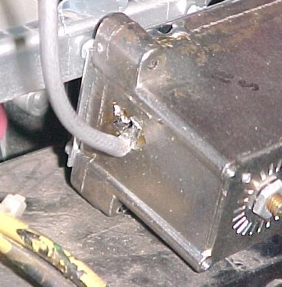
Prep your BNC to bare-end jumper so that it can go through the hole in the casting and the braid will flare at the casting.
Using your BIG soldering iron, tin the casting at the hole. Insert the jumper and solder the center conductor to the coil, and then solder the braid to the tinned spot on the casting.
I recommend that you use really flexible coax here, RG142 may stress the solder joint.
Mount the filter in the same way as the UHF instructions above, using 1/8" or so standoffs and 6-32 screws into the four corner filter cover holes.
The VHF receiver with the filter has a sensitivity of as good as .3 with careful tuning. Judging from the way it tunes up, it's still pretty sharp.
Go Back to Prep the Transmitter and Receiver radios