Revision 03/12/14
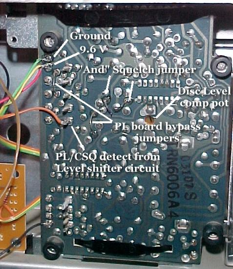
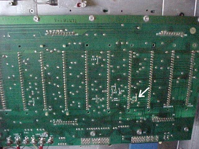
For a tone-controlled repeater, the jumpering is easy. The only jumper that will be in place is JU1.
All the others are out.
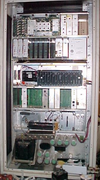
Note that this photo is of a standard RA/RT station.....any other micor model will have a different backplane.
Do Not mount the exciter and receiver yet, just get them and the chassis ready. They won't be hard mounted until after debugging and alignment.
Go ahead and connect them, but lay them in the compartments for testing.
In our original UHF mod, we drilled and tapped the back surface of the exciter compartment and through-bolted the exciter deck with countersunk head 6-32 screws. That's probably the right way to do it. We got over it. On every one we have done since, we glued the exciters in place with silicone bathtub seal, since we were basically soldering the chassis of the exciter to the chassis of the station with the final amplifier bond strip.
Position the exciter so that the final output transistor is visible through the hole in the station chassis that was used for accessing the PL reed.
The UHF exciter has a shield over the final transistor that you can solder to.
Solder your strip of copper sheet to the shield and after mounting the exciter in place, solder the strip to the station chassis. This gives you a total DC and PC board ground plane bond, as well as additional heat sinking to the chassis of the station.
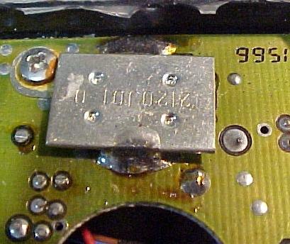
UHF Exciter final transistor shield
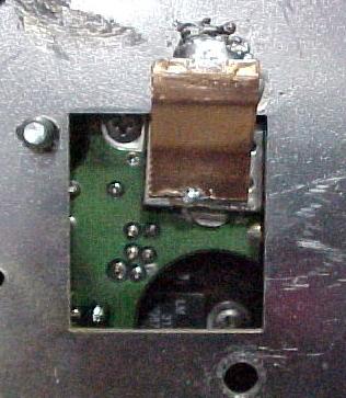
UHF Exciter mounted with bonding strip soldered to the transistor shield and the station chassis
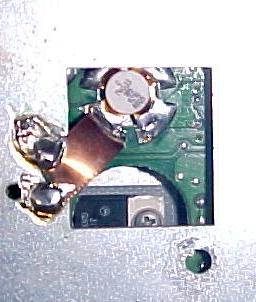
For some reason, the final output transistor regulator (visible through the round hold in the PC Board) gets hotter in the VHF radio than it does in the UHF radio. The jury is still out as to whether a means of heatsinking the regulator is neccessary.
Note: The tab of the regulator is at B+
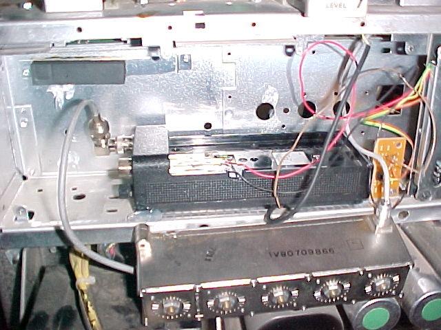
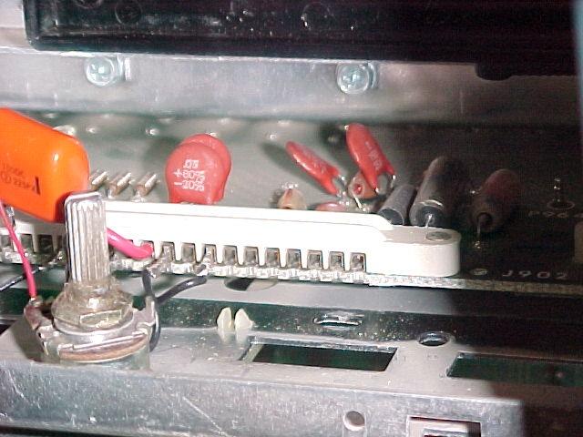
Exciter Connections
Pin 1 is at the right in this photo. Pins 8 and 10 must be jumpered. This fools the power control board into thinking that the old exciter is connected and is making delayed keying for reverse burst. If this jumper is not in place (also used in non-PL transmit stations) the station power amp will not come on. Actually, what happens is that the power control board looks for this signal to help it determine that the transmitter is keyed and that the power amp is making power. If this connection is not made, the power control board will shut the power amp down in about 200ms, thinking that there is a "no-power" condition in the antenna network.
Pin 11 is 9.6V supply to the exciter radio. ( Large red wire )
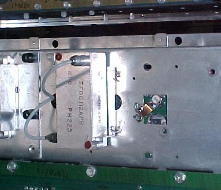
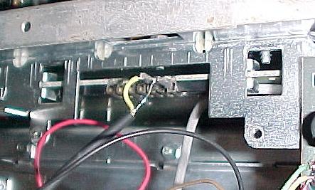
VHF Exciter Bandpass filter moved to the back of the chassis and SOLDERED to
the chassis sheet metal.
The bandpass filter is not used in the UHF station.
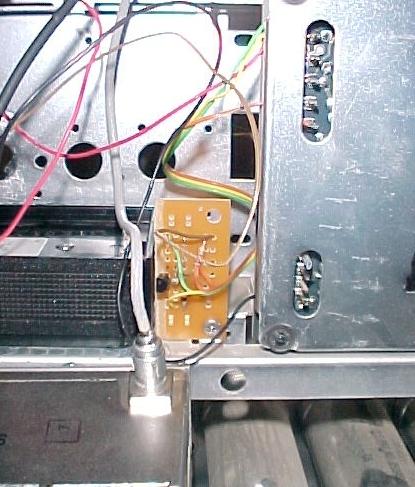
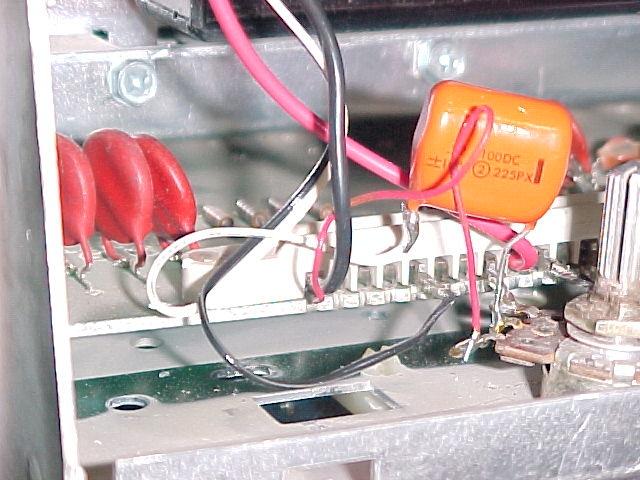
Continuing on the exciter deck connector, Pin 12 (next to the large red wire) is audio input to the exciter from the chassis. This pin goes to one end of the pot shown. The other end of the pot grounds at pin 19 along with DC ground to the exciter radio. We used salvaged board pins to make these connections plug in.
The wiper of the pot goes to the mic input of the exciter radio through a .22mf cap (that's what we used - 1mf np might be better) to provide DC blocking of the electret mic bias in the exciter radio. Since the transmit audio in the normal station DIRECTLY modulates the channel element, that audio level is way too hot for the mic input to the exciter radio. Hence the pot.
Pin 15 is F1 channel element ground, and is the fundamental PTT signal in the station. Normally, all the transmitter gain blocks (Tripler, etc.) are energized when PTT is asserted, but since the RF sections are all Class C nothing happens until the F1 channel element is grounded.
The PA is always energized. If you give it drive, it will make power, unless the power control board shuts it down. Therefore, all you have to do is key the exciter radio and it will go.
This is why you do not want to tie the channel element ground on.
Pin 15 goes to the PTT input of the exciter radio.
In the UHF station, take the double-female BNC bulkhead connector and install it in the little bracket you saved and re-install it in the chassis. Run your short BNC to BNC jumper from the exciter radio to the backside of this connector.
In the VHF intermittent duty station, there may not be room to mount the exciter AND the exciter bandpass filter in the compartment. We moved the exciter bandpass filter onto the back of the chassis.
Use a sufficient length of small coax to run from the exciter radio the bandpass filter. The existing coax from the intermittent duty PA should be long enough to reach the bandpass filter.