VHF Motorola MICOR Exciter Tuning Instructions
By Kevin Custer W3KKC
For
TLD5131
TLD5132
TLD5371
TLD5372
TLD8261
TLD8262
TLD4081
TLD4081
If a MICOR Test Set is not available, a needle type meter may be substituted if the meters basic movement is 50 uA. A Simpson 260 or equivalent is an acceptable substitution.
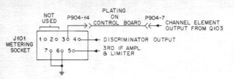
The "Test Set Selector Switch Position" also refers to the corresponding pin of the metering socket. In other words Meter Position 2 also indicates Meter Socket Pin 2.
Meter Socket Pins 6 and 7 are the ground return for the meter.
This diagram will help you understand the numbering
of the Metering Socket. Since it is accessable from either side,
ohm out pins 6, and 7 to understand orentation.
|
|
|
|
|
|
|
|
|
SET-UP - Connect the test equipment and set switches as shown. Key the transmitter with the XMTR ON button on the test set or microphone. | ||||
|
|
Power Set | EXCITER | OUTPUT - Turn POWER SET control fully counterclockwise. | ||
|
|
Frequency Switch | EXCITER |
|
REF A |
Channel Element - Select the desired frequency on multi-frequency radio sets. Key the transmitter. The test set meter 2 should indicate at least 10 uA. |
|
|
All Exciter Coils | EXCITER |
|
REF A |
Pre-Alignment - If the exciter is completely untuned and shows no meter 3 readings, set cores of all tuning coils to the top of their coil forms (away from the circuit board) and proceed with step 5. If the exciter shows meter 3 readings set cores of all tuning coils except L401 and L402 to the top of their coil forms (away from the circuit board). Tune L401 and L402 in that order for maximum meter indication. Go to step 7 of the procedure. |
|
|
L401 | EXCITER |
|
REF A |
Modulator Output - Tune L401 for minimum meter reading. |
|
|
L401
L402 |
EXCITER |
|
REF A |
Modulator Output - Tune L402, then L401 for peak meter reading. |
|
|
L403 | EXCITER |
|
REF A |
Tripler Output - Tune L403 for minimum meter reading. |
|
|
L403
L404 |
EXCITER |
|
REF A |
Tripler Output - Tune L404 and then L403 for peak meter reading. |
|
|
L405 | EXCITER |
|
REF A |
First Doubler Output - Tune L405 for minimum meter reading. |
|
|
L405
L406 |
EXCITER |
|
REF A |
First Doubler Output - Tune L406 and then L405 for peak meter reading. |
|
|
L407 | EXCITER |
|
REF A |
Exciter Output - Tune L407 for minimum meter reading. |
|
|
L407
L408 |
PA |
|
REF A |
Exciter Output - Move the metering plug to the PA. Tune L408 and L407 for peak meter reading. |
|
|
Repeat steps 6, 8, and 10. | ||||
|
|
Align the Power Amplifier. |
Copyright 1997 to present, Kevin K. Custer W3KKC
All Rights Reserved.