Up two levels (Motorola index)
Back to Home
Mobile Radio
Accessory Connector
By Robert W. Meister WA1MIK

|
Up one level (CDM index) Up two levels (Motorola index) Back to Home |
Motorola CDM-series Mobile Radio Accessory Connector By Robert W. Meister WA1MIK |
|
The CDM-series mobile radios use a 20-pin locking accessory connector, Digikey p/n 104422-2-ND. The middle 16 pins will accept the standard MaxTrac/Radius/GM300 16-pin locking accessory connector, Digikey p/n 104422-1-ND. The same physical contact pins are used; one is Digikey p/n 1-87309-3-ND. The connectors are made by AMP and can also be bought at Digikey and Mouser. Some of the pins have the same signals on both radio series; these are listed in the "Eq" column. Pin numbers and signal names in square brackets are defaults or suggested alternatives. The programmable Digital Input and Output pins are terminated with some resistance to ground or a supply voltage. Like the GM300 the pins (other than pin 4) programmed as outputs are driven low by transistors that pull to ground. Only pin 4 can actively pull up.
Unlike the MaxTrac/Radius/GM300, you don't need any jumpers installed on the accessory connector to make the radio operate with the internal speaker. In fact, you don't even need to plug in an accessory connector at all.
Accessory Connector Pin Assignments:
| Pin | Eq | Signal Name | Termination |
|---|---|---|---|
| 1 | 1 | Speaker Output (Negative) | |
| 2 | 2 | External Microphone Audio Input | |
| 3 | [3] | Digital Input 1 [PTT] | 4.7k to 5V & 47k to Gnd |
| 4 | 4 | Digital Output 2 | 4.7k to 12V |
| 5 | 5 | Flat TX Audio Input | |
| 6 | 6 | Digital Input 3 | 10k to 5V |
| 7 | 7 | Ground | |
| 8 | 8 | Digital Input/Output 4 | 4.7k to 5V |
| 9 | [9] | Digital Input 5 with Wakeup [Emergency] | 47k to 5V |
| 10 | 10 | Digital Input 6 with Wakeup (Ignition) | 4.7k to Gnd |
| 11 | 11 | Flat/Filtered RX Audio Output | |
| 12 | 12 | Digital Input/Output 7 | 4.7k to 5V |
| 13 | 13 | Switched B+ | |
| 14 | 14 | Digital Input/Output 8 | 4.7k to 5V |
| 15 | No | RSSI | Received Signal Strength Indicator |
| 16 | 16 | Speaker Output (Positive) | |
| 17 | --- | BUS + (Programming/SCI+) | |
| 18 | --- | Boot Control | |
| 19 | --- | N. C. | |
| 20 | --- | N. C. |
Notes About Specific Pins:
Pin 4 is the only pin whose circuitry floats low and actively pulls high to to +12V, all the other pins float high and actively pull low. This pin is capable of driving a low current relay coil, where the contacts could activate a horn or light for signalling purposes.
On my CDM1250, when pin 7 is jumpered to pin 9 and power is applied to the radio, the radio turns on automatically. This may be the meaning of "with Wakeup". Without this jumper, I needed to press the power on button (the front panel VOL knob) to turn the radio on.
Pin 10 is used for Ignition Control. You must supply +12V to this pin to turn the radio on, and of course program the radio to use Ignition Control. There are no internal jumpers or fuses to deal with, as with the MaxTrac etc.
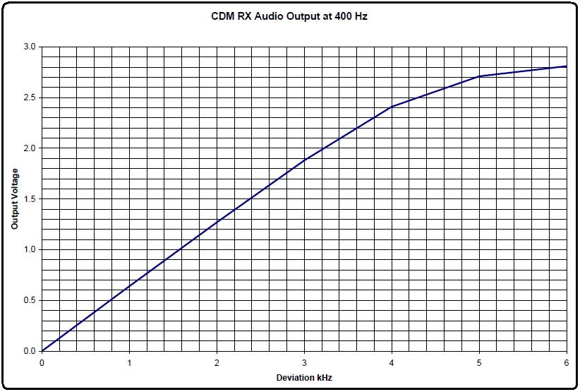
On my radio, pin 11 (RX Audio Output) was producing filtered (de-emphasized) and muted audio. With a 400 Hz tone deviated at 3 kHz on a wideband channel I measured 1.88VAC, or about 0.63VAC per kHz of deviation with a 400 Hz tone. (The detailed service manual states 630mV for filtered and 330mV for flat audio.) The level followed the standard 6dB/octave de-emphasis curve, however it started limiting slightly at 4 kHz of deviation. The graph below shows the output voltage.
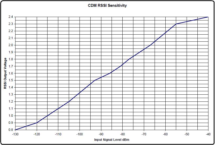
Pin 15 is RSSI - an analog voltage output. It went from 0.8VDC with no signal to 2.4VDC with the strongest signal. The graph below shows this voltage.
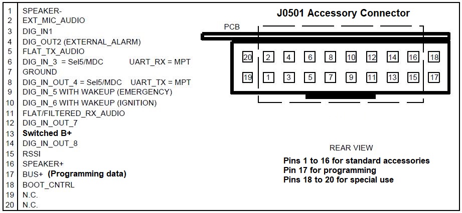
Accessory Connector Orientation:
The diagram below was extracted from the Detailed Service Manual. Note that the locking tab for the accessory plug is on the bottom edge of the connector, which is closest to the bottom of the radio when looking at it from the rear.
Digital (Programmable) Input and Output Pins:
Pin 10 of the CDM accessory connector is not programmable; it's always Ignition Sense. Pin 9 can only be programmed for Null or External Emergency Switch (Input). All the other pins (3, 4, 6, 8, 12, 14) can have the following functions assigned to them, depending on whether they are Input, Output, or Input/Output. The pins can be active high or active low, and on the input pins, with or without Debounce. The lists below have been sorted alphabetically; the choices will be in a different order when viewed in the CPS.
Input Signal Selections:
| Channel Select 1 |
| Channel Select 2 |
| Channel Select 3 |
| Channel Select 4 |
| Data PTT |
| Data Revert |
| Emergency Input |
| External Call Button 1 |
| External Call Button 2 |
| External Mic. PTT (Default for Pin 3) |
| LS RPTR Control |
| Mic. Off Hook |
| Null (No Function or Purpose Assigned) |
| Option Board 1 |
| Option Board 2 |
| Option Board 3 |
| Option Board 4 |
| PA Switch |
| Request To Send |
| Rx Audio Mute |
| Special Off Hook |
| TOC Disable |
| Tx PL Inhibit |
Output Signal Selections:
| Auxiliary Control 1 |
| Auxiliary Control 2 |
| Clear To Send |
| CSQ Detect |
| External Alarm |
| Null (No Function or Purpose Assigned) |
| Option Board 1 |
| Option Board 2 |
| Option Board 3 |
| Option Board 4 |
| PL and CSQ Detect/Talkgroup Detect |
Acknowledgements and Credits:
The diagram of the accessory connector came from the CDM and PRO Detailed Service Manual, p/n 6881091C63-O.
Signal Assignment information came from Professional Radio CPS Version R06.12.09 (the final version).
16- and 20-pin connectors and connector / interfacing kits / cable kits can be purchased from ebay seller "mre1032" (Kurt Meltzer, KC4NX / WB9KNX, Meltzer Radio Engineering).
Contact Information:
The author can be contacted at: his-callsign [ at ] comcast [ dot ] net.
Back to the top of the page
Up one level (CDM index)
Up two levels (Motorola index)
Back to Home
This page created on Saturday 08-Oct-2016.
Article text, artistic layout, and hand-coded HTML © Copyright 2016 by Robert W. Meister WA1MIK.
This web page, this web site, the information presented in and on its pages and in these modifications and conversions is © Copyrighted 1995 and (date of last update) by Kevin Custer W3KKC and multiple originating authors. All Rights Reserved, including that of paper and web publication elsewhere.