Up two levels (Moto index)
Go to the Home page
By Mike Morris WA6ILQ and
Robert W. Meister WA1MIK

|
Up one level (Genesis index) Up two levels (Moto index) Go to the Home page |
An overview of the Genesis Series Mobile Vehicular Adapter (MVA)
By Mike Morris WA6ILQ and Robert W. Meister WA1MIK |
|
The Mobile Vehicular Adapter (MVA) made for the Genesis series of hand-held radios was a natural progression from the prior (crystal controlled) HT220, MT500, and MX series handhelds. This started out as a mobile charger for the handheld battery - essentially a metal box under the dashboard contining a battery charger and a "pocket" that the radio slid into.
The HT600 radio manual describes the "NTN5438A 12VDC Control Unit / Vehicular Charger with PAC-RT Operation". That unit was, as described above, a mobile charger, but with a couple of extra switches. It had a front panel switch that was labled as a mobile extender on/off control, and a second switch that detected the radio in the pocket. When the enable switch was on, and the radio out of the pocket the extender was actually enabled.
The idea of a crossband mobile repeater had been copied by the commercial 2-way manufacturers from the amateur community and Motorola came out with the "PAC PL" and "PAC RT" products (the "PAC" was an acronym for "Portable Area Coverage", and the PAC‑RT was the better of the two).
As part of the Genesis Line development the "Convert-A-Com" was completely redesigned to clamp the radio into the charger pocket (both the US Forest Service and the military had complained - loudly - that the radios bounced out of the chargers on rough roads), to add both a channel display and a mobile microphone and speaker, and was given a new name: the Mobile Vehicular Adapter (MVA). Despite the new name some folks still call them a "jerk-and-run". The Genesis Line MVAs come in two versions, the basic, and the enhanced.
The basic MVA is the NTN5612A, and essentially functioned as a mobile storage receptacle in that it only slow-charges the handheld battery. Yes, you can add the parts to add the rapid charge feature to a basic MVA.
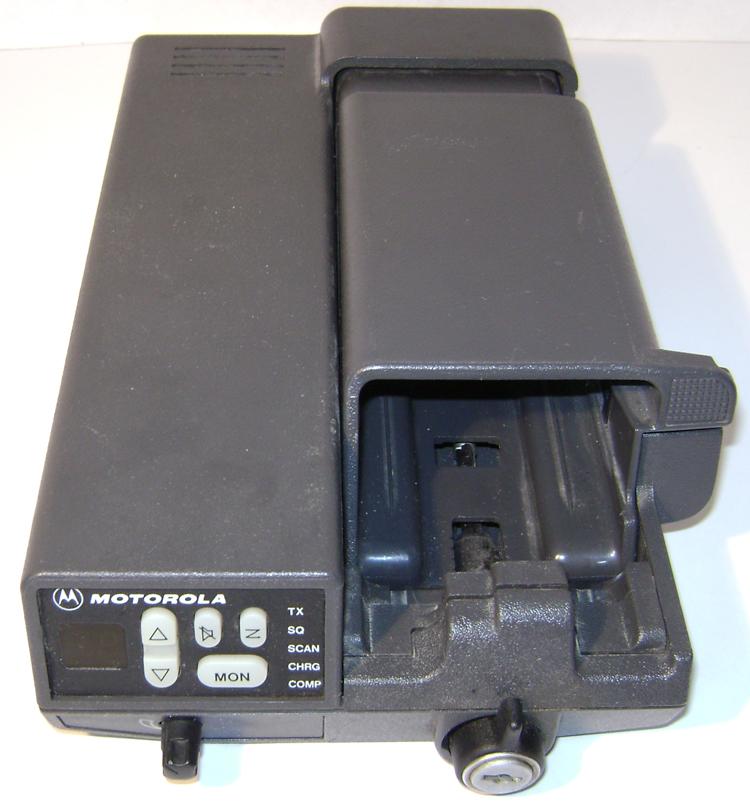
The enhanced MVA - the NTN5613A - provides rapid charging and has a two digit display and several control switches on the front allowing channel selection, scanning, and more. It also has the radio-in-pocket switch for the extender enable fuction. The enhanced MVA works just fine with any of the low band handhelds, but requires the "B" series high band or UHF MT1000s / HT600Es or later for the display and control switches to work as the early firmware (in the "A" series) does not know about the MVA switch and display panel. Look at the second-last letter of your handheld model number - for example, a radio with the model number H44GCJ-7190BN is an issue "B" radio. Occasionally you see a radio without the last letter (like in H44GCJ-7190B)
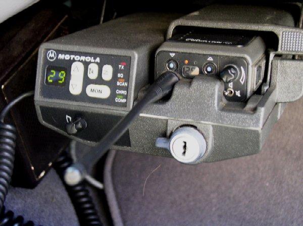
The photo at the top of the page is of an NTN5613 in use (in fact the photo shows it in the transmitting mode) courtesy of Mark Tomany N9WYS. BTW, the LED labeled "COMP" indicated that the battery charging cycle is COMPlete. Another view is here.
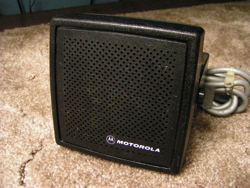
If you want an MVA look for a NTN5613A or NTN4613B, but make sure it comes with the bracket, the amplified speaker and the bracket for that speaker. The NSN6054A External Speaker with its internal 12-Watt audio amp is a required part of the MVA kit. I'll say it in a different way - if your surplus MVA does not come with the matching bracket, the NSN6054A speaker and its bracket, don't buy it (or plan on having to do some creative experimental electronics to make a substitute speaker work). Then you get to install it into your vehicle. After a week of being told that you are flaky into the repeater you will want to add an external RF amplifier, and at that point you may realize that you have more money into the MT1000, the MVA, the speaker and the RF amp than if you'd just bought a Icom, Kenwood or Yaesu ham radio, or a surplus 128 channel Spectra (don't forget to recap it)...
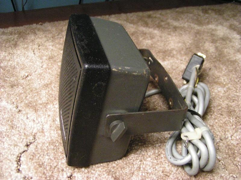
The NSN6054A looks like a normal speaker from the front, but the side
view shows just how deep it really is. The bracket (part number 0705152E01)
is extra deep and is NOT common. The cable is seven conductors and has a
male DB-25 plug on it. More info on the NSN6054A further on down this page.
These two photos by WD9HSY.
Several external RF power amplifies were an option on the MVA and which one came with it depended on the band and split. There were ones for low band, high band and UHF, but all were single band (to my knowledge, Moto has never offered a dual band amplifier, but I have seen several MVAs that have been cabled to aftermarket ham radio dual band amplifiers).
There are several different RF power amplifiers that are part of the MVA kit:
Moto offered amplifier kits such as the NLD7701 (136-150 MHz), the NLD7702A (later changed to PLD8000A, both built for 150.8 - 174 MHz), the NLE8911 (406-420 MHz), the NLE8912 (450-470 MHz), the NLE8913 (470-494 MHz) and the NLE8914 (494-512 MHz) consisting of the amplifier and all appropriate cables.
The 4-pin power cable that plugs into the back of the MVA uses a standard polarized Molex connector, but I do not know the Molex, DigiKey or Mouser number. The Motorola part number for the cable is 3005442T03, but Motorola does not list the connector as an orderable part by itself.
The lock at the bottom front of the MVA used different keys depending on if the MVA was a standard product or delivered with a specially ordered fleet - i.e. If you are going to purchase one on eBay (or anywhere else, for that matter) make sure the unit uses one of the standard keys (I've seen them with both a MOT-1 and with a 2135), comes with a key, or plan on buying a half hour of your local locksmith's time to make a key).
The MVA service manual number is 6881062C75, but the schematic has been
scanned for you: Page 1
Page 2.
The full instruction manual has
also been scanned. A 2.9 MB PDF file can be found here.
Click here for the MVA
operations manual (part number 6881082C70-O), a 3.9 MB PDF file courtesy of K5ZZT.
There are 2 small switches on the back of the MVA. One is in series with pin 7 of the radio accessory connector and allows selection of the radio speaker versus an external speaker (up for internal radio speaker, down for an external mobile speaker). Trust me, you will want the external speaker. The other switch is relevant only on a 99 channel radio and causes the display to flip over when the radio is inserted into the MVA so you can read the channel right side up. This feature is dependent on the "MVA FLIP" option being enabled in the codeplug (i.e. in the RSS).
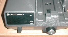
The NTN5612 has a plain front panel as shown in the photo below left - just the transmit and charging complete vertical LEDs on the right, and the Moto logo. In contrast, below right is a photo of an NTN5613 - to the left of the up/down channel rocker buttons is a 2-digit green LED display (early red ones were were almost unreadable in bright sunlight). I've seen one with an LCD display that was quite readable in the day, and illuminated at night, but I do not know if that was one persons personal hack, was a Moto special product, was a late production item, or a prototype that escaped into the field.
The mobile microphone plugs into an RJ45 connector on the left side. The microphones specified in the manual are the same microphones as are specified for a Maxtrac:
 The black protrusion on the left front is the volume control. |
Click on this photo for a larger image.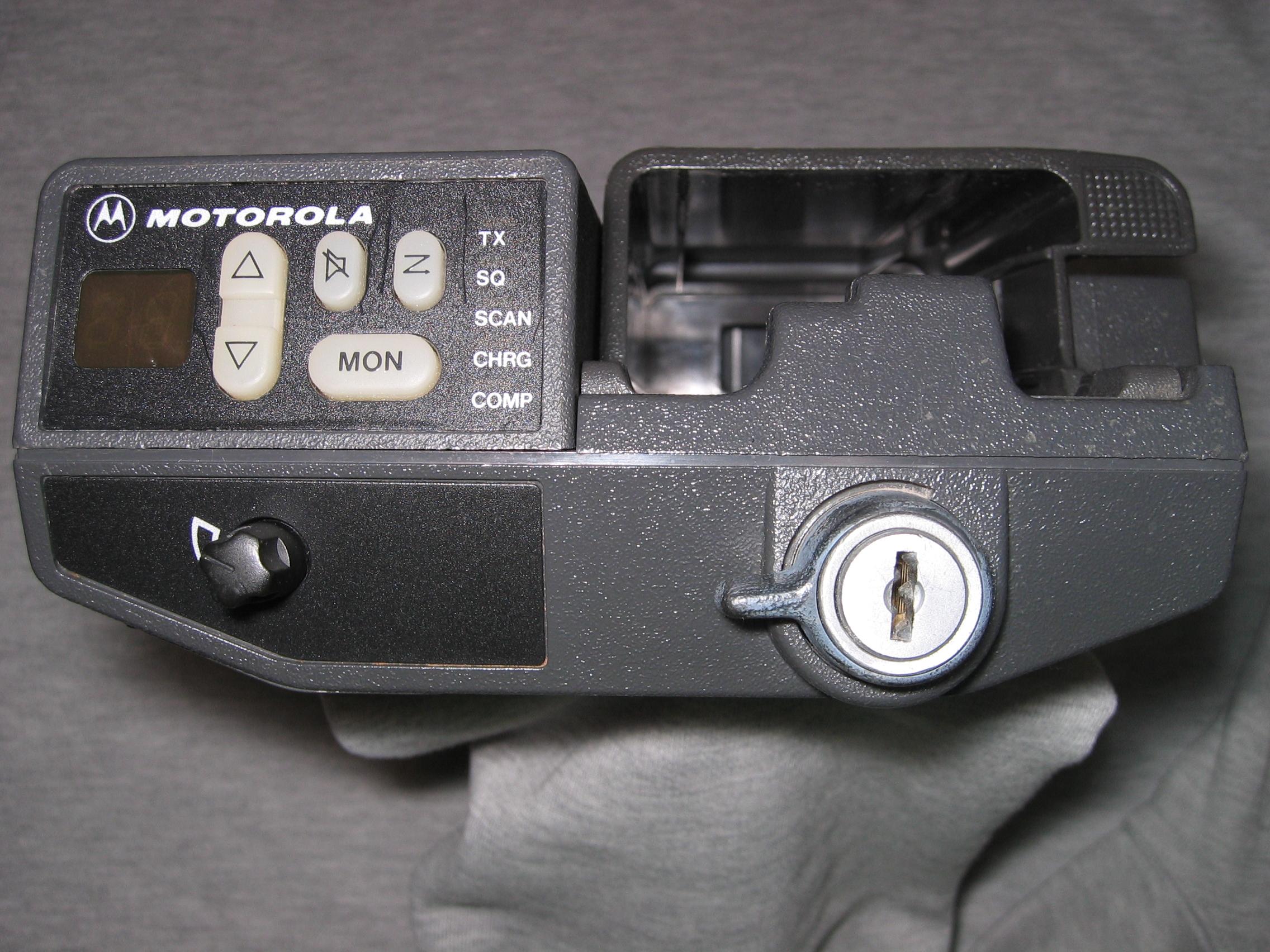
|
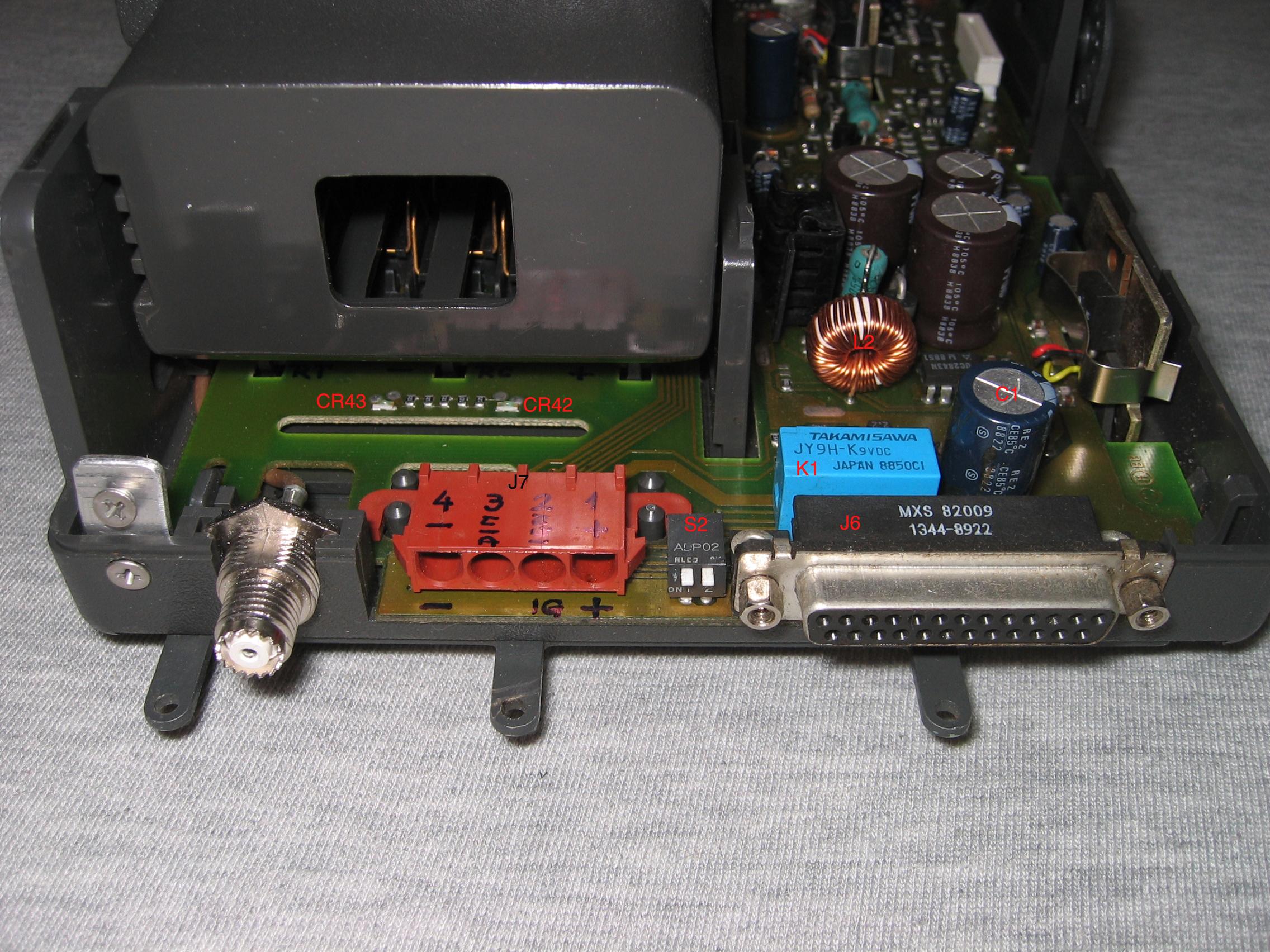
The back of the MVA has a DB25 female connector, the two DIP switches
mentioned above, a 4-terminal DC power connector and a mini-SO-239 coax
connector:
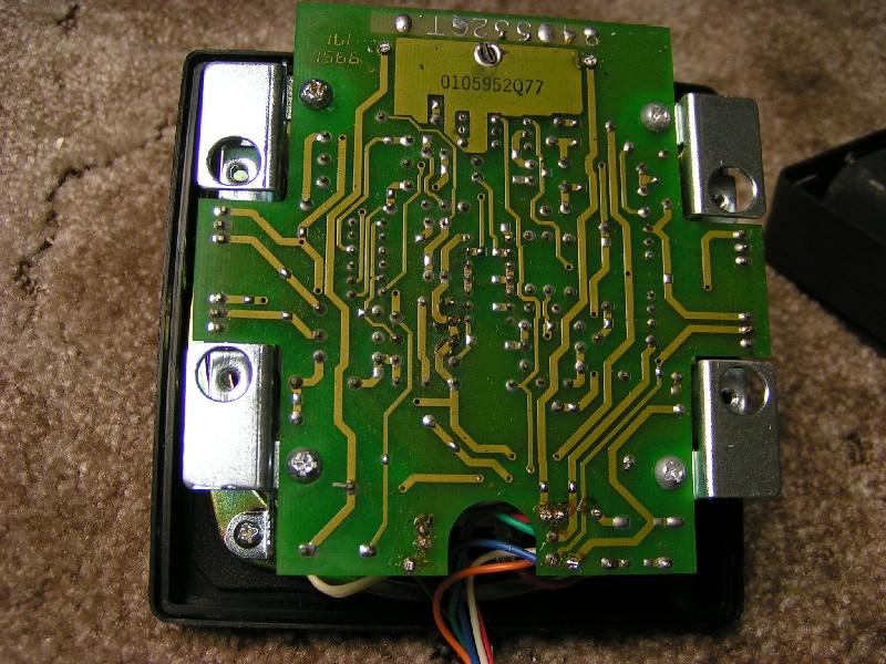
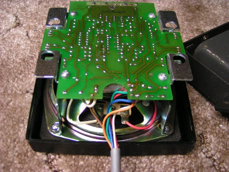
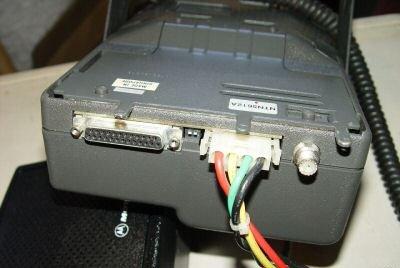 Click here for a photo of the interior with the pocket removed. |
|
DB-25F Pinout: View is looking at the face of the socket, or at the back of the plug that is inserted into it. |
||||||||||||||||||||||||||||||||||||||||||||||||||||||||||||
|
|
|
||||||||||||||||||||||||||||||||||||||||||||||||||||||||||
NSN6054A external speaker pinout: (this is
the DB25M plug on the end of the speaker cable)
The NSN6054 series of speakers was designed for use in both negative and positive
ground environments, hence the "Assignment" column showing "-12vDC"
and "+12vDC". Despite the misleading text, this is a 12vDC amplifier, NOT
24vDC! In a negative ground vehicle installation pins 2 and 3 end up at ground
potential and pins 11 and 24 end up at +12vDC. Yes, the are two power leads in parallel
for the positive side, and two more for the negative, just because of the small diamater
conductors and the current drain.
| Pin | Color | Assignment | Comment |
|---|---|---|---|
| 2 | Black | -12vDC | jumpered to pin 3 |
| 3 | Brown | -12vDC | jumpered to pin 2 |
| 5 | Green | Amplifier control | This is a DC logic that turns the audio amplifier inside the speaker on and off. The manual calls this signal "Squelch". |
| 11 | Red | +12vDC | jumpered to pin 24 |
| 20 | White | Audio from handheld | One side of the speaker audio (floating) |
| 21 | Blue | Audio from handheld | The other side of the speaker audio (floating) |
| 24 | Orange or Yellow |
+12vDC | jumpered to pin 11 Some cables use an orange wire, some use a yellow wire. |
Courtesy of WD9HSY here are two photos of the interior of the NSN6054A. The two
metal brackets that hold the circuit board in place also function as heat sinks for
the 12 watt audio amplifier.
For what it's worth, the
NSN6027A series of amplified speaker is similar to the NSN6054A except that it
was designed for the Convert-A-Com that was made for the MX-series of handhelds.
Here's a way to use one of
these units as a general-purpose amplified speaker. The HSN1000A is a similar unit
and is Mostar vintage. The TSN6015A is Motrac / Motran vintage and was made
for those plus the mobile adapters made for the HT200 and HT220 series handhelds.
All of them are pretty similar inside except that the early ones are germanuim
transistor based, have no muting circuit, and the pinout and wire colors are
different. I've not seen the schematics but if they have the floating audio
input circuit you could rewire any of them to work with the Genesis MVA. If they
have a grounded audio input you would need to add an audio transformer.
Here's the 6881100E70 documentation on
the TSN6015A unit, a 1.8 MB PDF courtesy of Bruce Carpenter W3YVV
MVA Power connector pinout:
| Pin | Assignment | Color |
|---|---|---|
| 1 | +12vDC (Vehicle Battery) | Red |
| 2 | Ignition switch +12v (when equipped with the PAC-RT option (the mobile extender) switching the ignition on caused the mobile extender to drop into off-line mode. | Yellow |
| 3 | Headlight switch (usually is connected to the tail-light wire so it gets 12v when either the parking lights or the headlights are on). When connected to +12 this lead causes the display to dim. | Green |
| 4 | Ground | Black |
Modifying the Battery Charger in the MVA
The "basic" MVA is trickle-charge only, the "enhanced" MVA has the components for
rapid charging Nickel-Cadmium based battery packs and switching to trickle mode
when they are fully charged. The switchover is based on a thermistor sensing the
temperature of the cells in the pack. Nickel-cadmium batteries have a different
heat response than NiMH batteries and some battery maufacturers use the same
thermistors for both Nickel-cadmium and NiMH batteries. The solution to this is
described in the article on modifying the desktop
rapid charger. I suggest that you go read it, then come back here. In short,
if you drop an NiMH battery with the wrong thermistor into any unmodified
charger for even just one charge cycle you can overheat it to the point of
permanently ruining it.
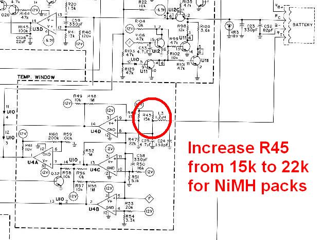
The fix is to change the value of R45 from 15k to 22k, but if there is even
a slight chance that you would stick a NiCD pack in the MVA you will want to change
R45 for the NiMH pack, then mount a SPST mini-toggle switch and wire it to shunt a
47K or 51K across the 22K resistor (resulting in an effective value of 15K) then
label the switch positions as "NiMH" and "NiCD". See the schematic below (the charger
circuit is identical to the one in the regular desktop rapid charger, but the component
reference numbers are different).
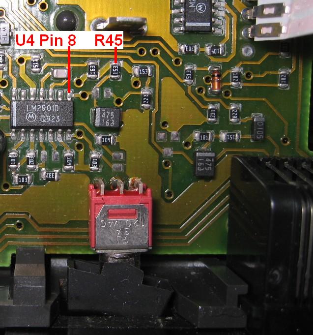
Here is a closeup photo of U4 and R45. The big black object in the lower right
corner is the microphone jack, and the switch enables the mobile extender. Once you
remove R45 you can install other components using the nearby feed-thru holes, as
there's one at each end of it. Personally, I'd remove the surface-mount R45, mount
the mini-toggle switch mentioned above, wire the two resistors to it, and then run
wires to the R45 feed-thru holes.
To be added: (contributions of information are welcome!)
Does anybody have any of the following that they would be willing to contribute?)
The model numbers for the previous "box" style Convertacoms.
Digital photos of:
The previous "box" style Convertacom (empty).
The previous "box" style Convertacom with a radio in it.
Contact Information:
The author can be contacted at: his-callsign // at // repeater-builder // dot // com.
Back to the top of the page
Up one level (Genesis index)
Up two levels (Moto index)
Go to the Home page
This page originally posted on 11-Apr-2007 by Mike Morris WA6ILQ
Artistic layout and hand-coded HTML © Copyright April 2007 and date of last update by repeater-builder.com.
Bob Meister WA1MIK contributed information on the mod to the battery charger
section of the MVA.
Mark Tomany N9WYS contributed part numbers of the power cable, the external
speaker, the manual number, the schematic diagrams and photo of the MVA and
some additional notes on it.
Brian Bedoe WD9HSY contributed the exterior and interior photos of the
external speaker.
Information on the accessories was obtained from Motorola's catalogs, service manuals and service bulletins.
This web page, this web site, the information presented in and on its pages and in these modifications and conversions is © Copyrighted 1995 and (date of last update) by Kevin Custer W3KKC and multiple originating authors. All Rights Reserved, including that of paper and web publication elsewhere.