Up two levels (Moto index)
Back to Home
PTT Keyed Line Modifications
By Sean Magowan VE2NRG

|
Up one level (GTX index) Up two levels (Moto index) Back to Home |
Motorola GTX High/Low Power and PTT Keyed Line Modifications By Sean Magowan VE2NRG |
|
Background:
For many of us, getting on the 33cm band can be a real challenge due to the fact that amateur built transceivers are basically not readily available on the market with only an exception (Alinco handheld that covers 900 MHz). For others, they have turned to the use of transverters from many renowned builders and for the rest, simply grab an easily converted to ham use commercial radio (Motorola GTX or Kenwood TK-980). Quite honestly, for my part, I wanted to do something simple and cheap to test out the 900 MHz (33cm) band and experiment with it. I had been grasping the idea of doing something different that I do not think had been done before so I dove right inn. My work and ideas were laid down on paper and I started the project. I wanted to have a solid FM 900MHz link with my buddies at 35 miles and 68 miles away, so first things to have are low loss coax and an antenna (LDF5 and a 16.5dB loop antenna). These should do just great.
Already having 2 GTXs here at home I decided it was time to mod them and run the 33cm band. Configuring the radios and all was quite straightforward and they can get on the ham band very simply. That is already covered on the repeater builder website so I will not go over this basic mod here but will give you the link: www.repeater-builder.com/motorola/gtx/gtx-index.html. It is a great write-up and deserves two thumbs up!
Once everything was done I fired up the radio and could program the channels I wanted using the Motorola GTX RSS software. I played around a bit until I decided to check output as some talk on the repeater builder web site mentioned erratic power when out of the pre-programmed band plan. As a matter of fact, I was going from 0.7W to 16.3W! This of course forced the power modification explained here: www.repeater-builder.com/motorola/gtx/gtxpwrctrl.html.
After the modification, power was set at a perfect 12.5W across the whole ham radio band! I was very pleased and so my project was complete! Or was it?
Now that all was done, being who I am, I wanted something more, a little more power! But how? An amplifier, of course was the answer! However, these radios do not have anything for amp control etc and they run 12W output! I looked around and found some great reviews on a Motorola Paging AMP that does 150W continuous duty and it's a class AB amp so that means it could be used as well on FM or SSB. Sweet stuff!! The model I am going to talk in this modification is the STF-2520A: www.qsl.net/n9zia/stf2520a/index.html.
So on to the work.
Modifications:
Now just to set things straight, the basic modifications for the power and for the amplifier modifications have been used from the repeater builder site and I am thankful to the designers and people who made them possible. I have added up to these to offer even more flexibility to our readily available GTX and STF-2520A amplifiers.
Basic steps are:
New steps to modification are in the following texts. This is where I decided to go further with the GTX and would like to thank Bob WA1MIK and Jimmy VE2JWH for their great help at making these modifications possible.
Here is a basic explanation of what my modification does and why it is useful to the GTX users. First, we are using a now modified GTX that runs at 12W and this is too much for an amplifier drive. Second, how on earth are we going to get this to key the amp? Third, we will be using this radio to transmit and receive, right? Then don't we need a way to tell the amplifier which mode we'll be in? The answers are: YES: 12 watts is too much drive. Yes: we need a way to key the amp. Yes, we do need an RF coaxial switch setup to get the job done! So folks, here it goes.
First things first, we need to build up from the power regulator circuit that Bob WA1MIK made and develop it into a high and low circuit that will allow us to select high or low power so we can use the amplifier at a lower power setting and the standalone radio on high power. The idea is good, but I also wanted to add a foolproof design that would not allow it, when set for high power, to key the amp and thus blow it up with way too much drive. Sort of like a defense system in case the operator forgets to put it to low setting. Second, we need a KEY output that will allow us to use that signal to drive a relay to key everything.
I think it's a much easier approach to show you the circuit design and you should be able to see what is going on in the circuit. You can see the diagram of the modification below. Click on any of the photos or diagrams for a larger image.
 Diagram #1.
As you can see, we are using a small switch to do two things, and one relay to do key control.
The switch has two functions: it's a user selectable power high/low switch but it also activates the Keying transistor to allow for a Keying ground signal to be generated when on the low power setting. This is a foolproof way of linking both so that no errors are made that can damage the power amplifier's input.
The relay has the basic job of switching the ground to a closed circuit to allow the amplifier to be biased upon keying radio. In case this relay would fail, you still would be on low power but not biasing the amp! So you have a nice safe circuit. Being at 900MHz, wavelength is also very important to think about, so since some wiring is going to be going outside of the chassis, some 0.01uF capacitors have been used to prevent any RF from returning into the circuitry and causing any oscillation or weird circuit behavior.
VARIABLE POWER CIRCUIT:
On the left you have the power circuit that allows for 12w to near 1w output. The low power level can be varied by increasing the value of R3. R4 and VR2 set the base for 12W at high power so adjust R3's value to get required amount of drive power to drive your amp depending on its required input. Experiment until the required drive is achieved.
KEYING CIRCUIT:
On the right, you have the keying circuit. This uses a few resistors, capacitors and a 2N2222 transistor to key the Biasing relay. We use the K9.1V source as a Keyer and the transistor takes the load to key the relay. This means the radio circuitry is unaffected by any current draw. The transistor does the work by using the 13.8v from radio. Inside picture of the installation:
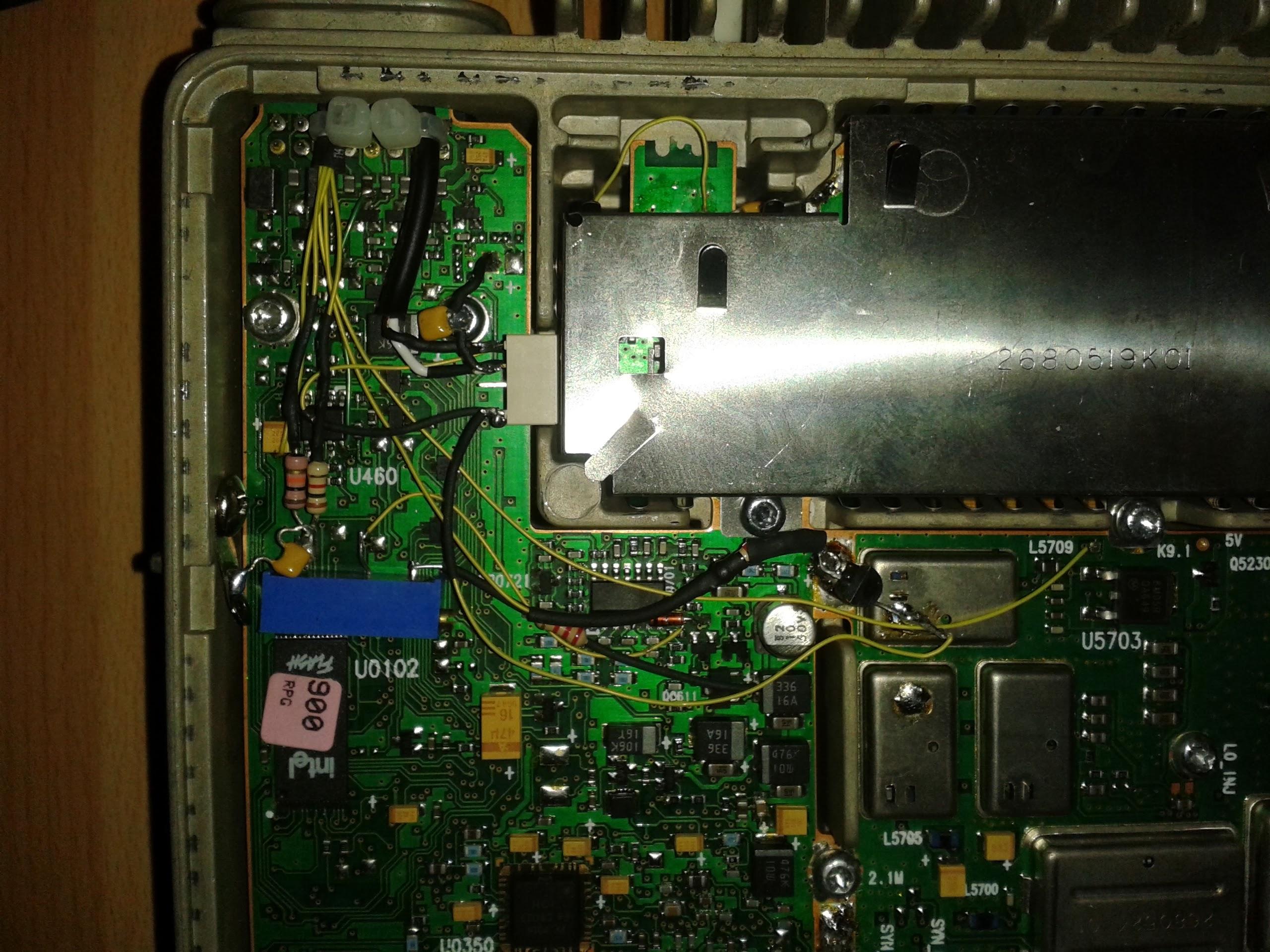 Photo #2.
When the PTT is keyed and the low power setting is selected, a ground path now exists on the RCA jack. At the same time, it uncouples the radio from the amplifier. I have also chosen to bring the switch out to the side of the radio and the RCA jack is fed via a shielded cable. Additional photos show the result.
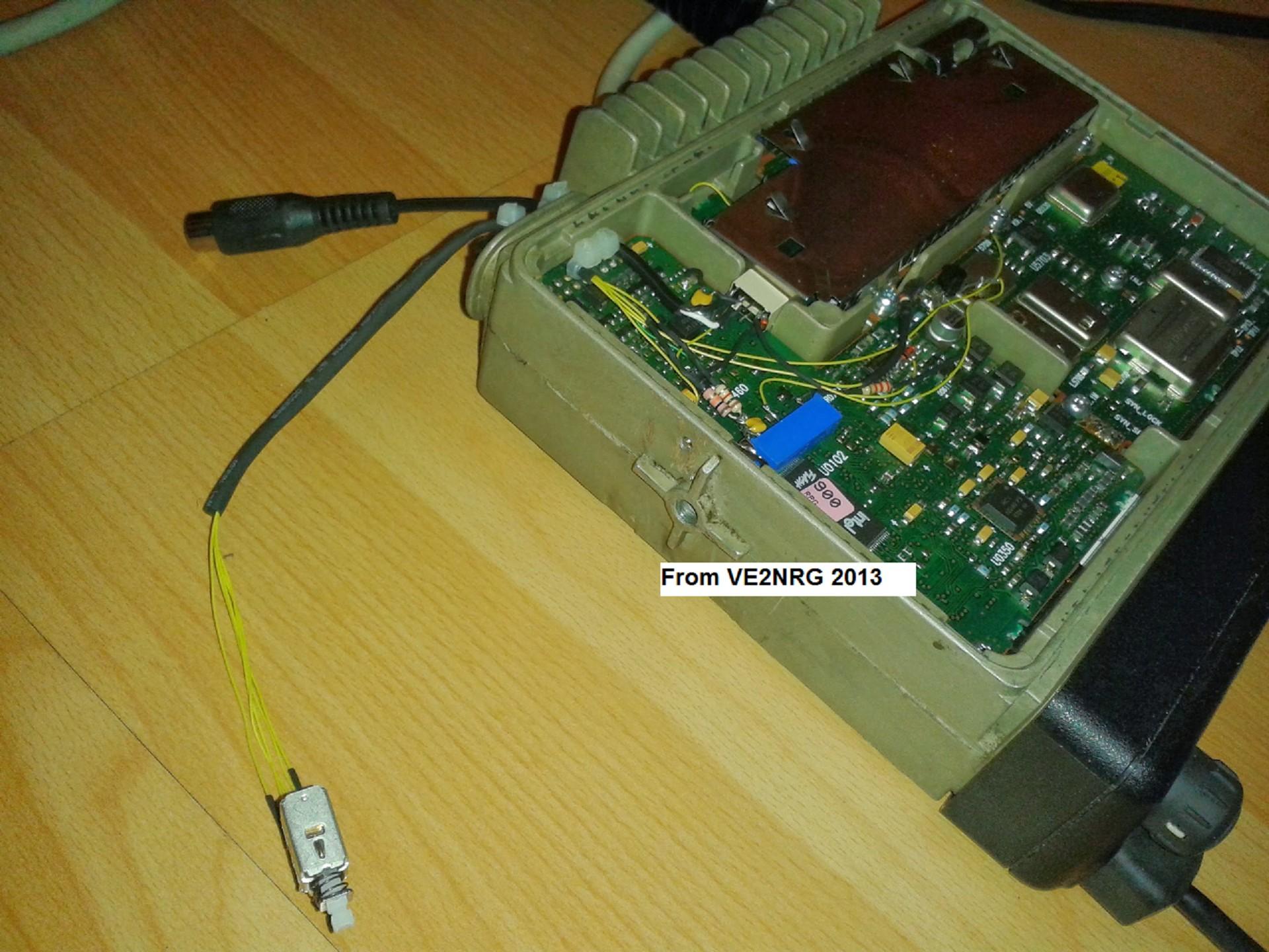 Photo #3.
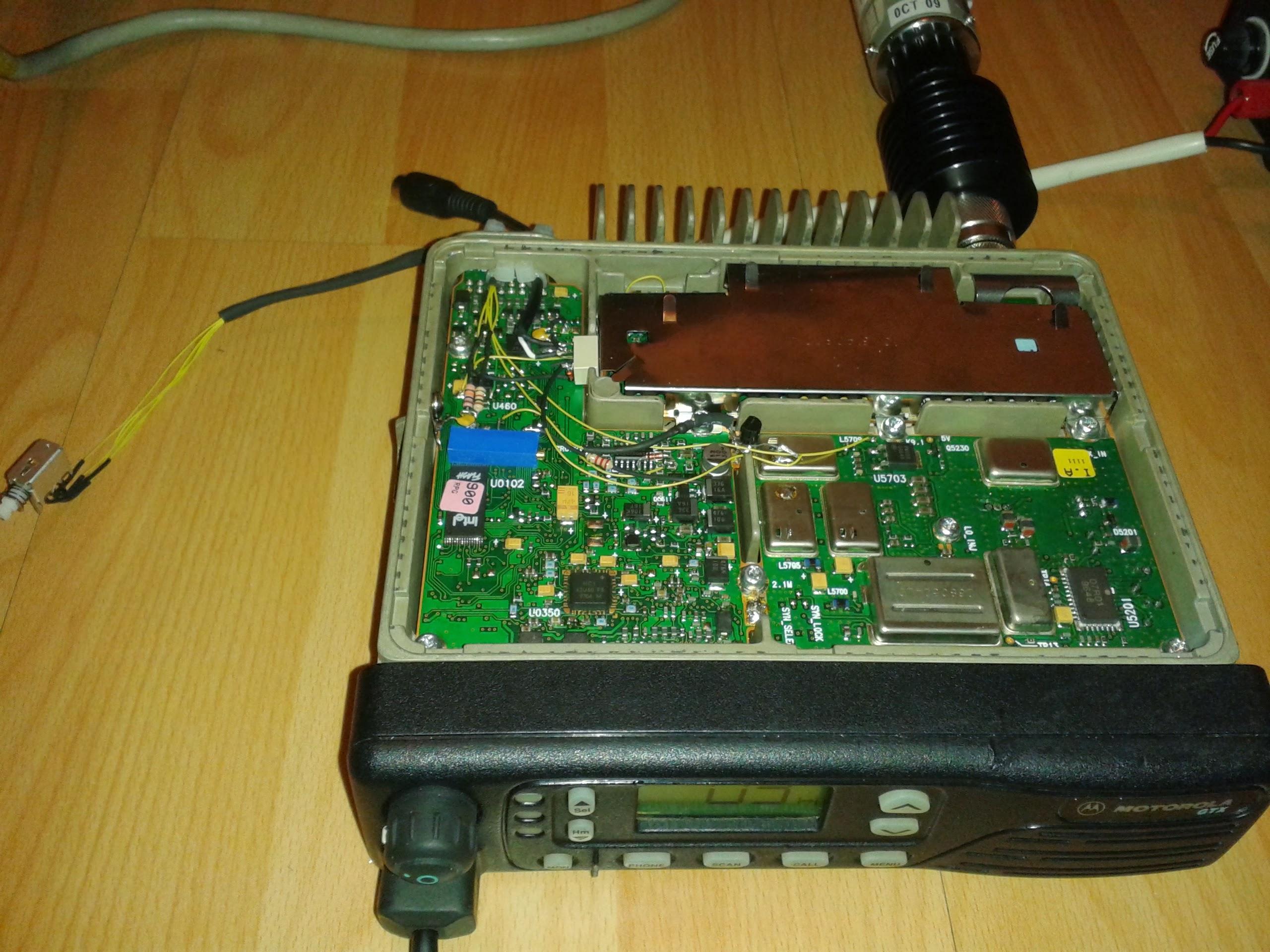 Photo #4.
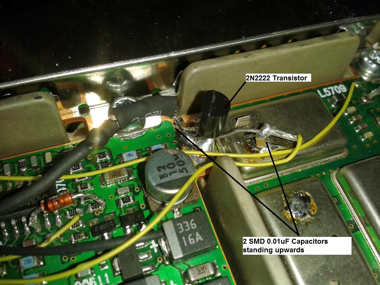 Photo #5.
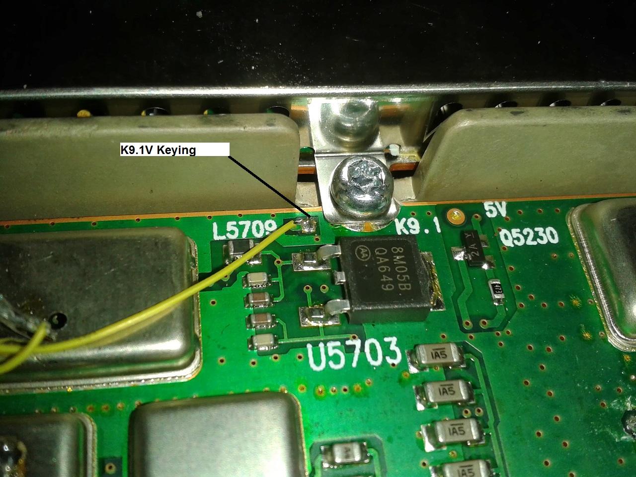 Photo #6.
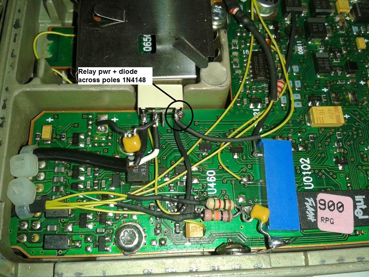 Photo #7.
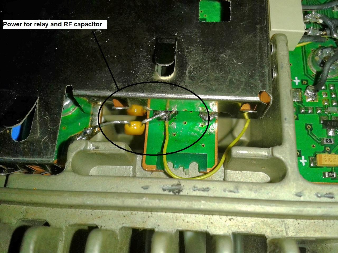 Photo #8.
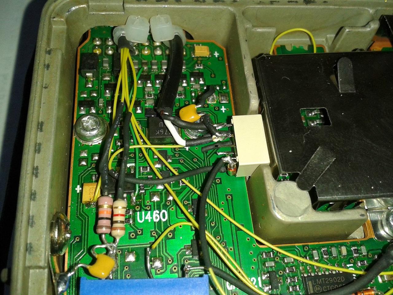 Photo #9.
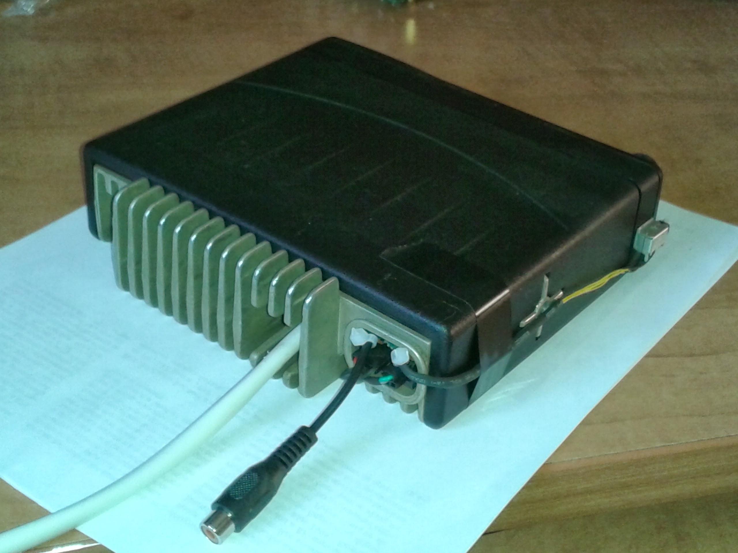 Photo #10.
Parts List:
| Qty | Part Description | Source or Part Number |
|---|---|---|
| 1 | Switch | Digikey: CKN1191-ND or equivalent |
| 1 | 12V Relay (fits perfect in hole) | Digikey: PB1205-ND or equivalent |
| 1 | 2N2222 Transistor or equivalent | Junk box or equivalent |
| 1 | Variable trimmer potentiometer | Digikey: 3006P-102LF-ND |
| 1 | Female RCA jack | Junk box or equivalent |
| Very small wire. I used #30 wire. | Junk box or equivalent | |
| 2 | 0.01uF SMD ceramic capacitors | Digikey: 399-6741-1-ND |
| 3 | 0.01uF radial ceramic capacitors | Digikey: BC1095CT-ND or equivalent |
| ? | Resistors: 2.2K, 2K, 1K, 6K8 and others to experiment with | Junk box |
| PATIENCE!!!!! |
Upon doing this modification, please note that the 2 SMD capacitors are placed upwards. See photo #5 above. This means one side is to ground and the other side is where you set the wire or resistor over it and solder it. They act as an RF suppressor.
Please note that this is a first write-up for me, so please take this into consideration when reading it.
Although I have put effort into describing this mod, if you feel anything is not clear or missing, please send me an email and I will gladly assist you as best I can.
Contact Information:
The author can be reached at: his-callsign [ at ] videotron [ dot ] ca.
Back to the top of the page
Up one level (GTX index)
Up two levels (Moto index)
Back to Home
This article was originally posted 28-Dec-2013.
This web page, this web site, the information presented in and on its pages and in these modifications and conversions is © Copyrighted 1995 and (date of last update) by Kevin Custer W3KKC and multiple originating authors. All Rights Reserved, including that of paper and web publication elsewhere.