Back to Home
M400 Interface Signals
By Robert W. Meister WA1MIK

|
MaraTrac index Back to Home |
Motorola MaraTrac and M400 Interface Signals By Robert W. Meister WA1MIK |
|
MaraTracs and M400s can be used for repeater receivers and transmitters. Just like their smaller cousins (MaxTracs, Radiuses, and GM300s), you need two radios, since none of these can operate full duplex. These also suffer from most of the same woes as MaxTracs: the transmitter will need a lot of cooling air and it should be run at no more than 50% of its rated power. The transmitter will probably shut down when the microprocessor thinks it's getting hot, so a manual power control might be necessary. (Perform the same modification to the logic board as for a MaxTrac; see that article on Repeater-Builder.) These radios also have an antenna relay that should be bypassed to eliminate a source of future trouble.
The biggest problem is that there are no spare pins on the control cable connector on the front of the radio, nor is there an external accessory jack to get additional signals in to, or out of, the radio. This is really only an issue for the receiver. If you're willing to run the radio with its cover off, or drill/cut an opening either in the top cover or somewhere in the casting, you can bring wires in and out of the radio. You should consider using feed-through capacitors for the signals, just to reduce the chance of signal leakage.
I prescribe to the "KISS" principle: "Keep It Simple, Stupid." The less modifications I have to make to a radio, the better. This also makes it quicker and easier to configure replacements, when necessary.
There are several articles about repeater interfacing using MaxTrac radios on this web site. This article will follow the simple scheme detailed there. The following signals are minimally required for any repeater setup:
There are usually multiple places each of these signals can be accessed; they will be detailed below, but first, let's see what's available at the various connectors throughout the radio.
NOTE: Most of the signals and observations described below are based on the configuration of my MaraTrac radios: low-band with advanced control heads (A7) and remote squelch. If you configure the radio for a different head type, some signals will be different.
Control Head Connector (J1) on front of radio:
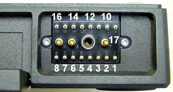
This connector normally feeds a control head. It is the only connection point accessible with the radio's covers installed. The pins and signals are described in the table below. Pin 1 is in the lower right corner when looking into the front of the radio with the connector at the right. The lower row has pins 1-8 (right to left), the upper row has pins 9-16 (right to left), and the large pins in the middle are 17-19 (right to left) with the jack screw between pins 17 and 18. All of these numbers are embossed in the plastic connector body and the photo has most of them identified.
| Pin | Signal Name or Use | Notes |
|---|---|---|
| 1 | Serial Clock | |
| 2 | Analog Ground | |
| 3 | Speaker High | Do Not Ground! |
| 4 | B+ from Control Head | Green Ignition Control wire |
| 5 | Speaker Low | Do Not Ground! |
| 6 | Data Out | |
| 7 | Display Enable | |
| 8 | Data In | |
| 9 | Busy Light | or Remote Squelch |
| 10 | Switched 5V | |
| 11 | Volume Top | |
| 12 | Push-To-Talk | Ground to Transmit |
| 13 | Power On/Off | Ground for ON |
| 14 | Microphone High | Has +9VDC on it |
| 15 | Volume Wiper | |
| 16 | Xmit Light | See comments below |
| 17 | GROUND (Black wire) | Large pin |
| 18 | Emergency / Hook | Large pin - Doesn't work |
| 19 | A+ (Red wire) | Large pin |
The Busy signal on pin 9 drives the Busy LED on the clamshell and handheld control heads, which follows the carrier only. On radios with Remote Squelch (only low-band MaraTrac radios have this feature), this line is used for the squelch pot signal. On the advanced control heads, the Busy and Xmit LEDs are driven by the serial clock and data lines that handle the channel display. In fact, most of the switches and LEDs run through the serial chips. The older non-synthesized radios that use the same connector (Motrac, Motran, etc.) rely on discrete lines for every signal; nothing is shared or multiplexed.
The Xmit Light signal on pin 16 is shared between the Light relay driver (Horn/Light option available at the VIP connector on the back of the advanced head) and the actual Xmit Light signal (a 5V TTL signal that eventually lights the transmit lamp in the clamshell head). In fact, some other signals change function depending on the type of control head the radio expects at the end of the cable.
If you remove the top cover of the radio, you now have access to a whole bunch of connectors and signal points, but you'll probably have to leave it off to use the radio in repeater service.
Programming Jack (J20) inside radio:
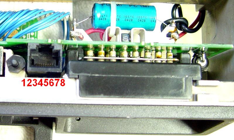
This is an RJ45 receptacle with signals similar to what you'd find on a MaxTrac, Radius, GM300, or GTX radio. They are described below. Pin 8 is closest to the main radio connector J1.
| Pin | Signal Name or Use | Notes |
|---|---|---|
| 1 | Switched B+ | |
| 2 | Spare | Available |
| 3 | Emergency / Hook | Doesn't work |
| 4 | Ground | |
| 5 | Microphone Audio In | Has +9VDC on it |
| 6 | Push-To-Talk | Ground to Transmit |
| 7 | SCI+ | Programming line |
| 8 | Handset Audio Out | Fixed level |
Option Board Connector (J22) inside radio:

This two-row connector is available for options and interfacing. For some reason, Motorola numbered the pins around the outside, rather than the traditional odd/even scheme used by most two-row connectors of this type. Pin 1 is located at the far left side of the radio, closest to the front panel. The pins are then numbered counter-clockwise, with pin 3 being a keyway. The table below describes the signals available here.
| Pin | Signal Name or Use | Notes |
|---|---|---|
| 1 | Digital Ground | |
| 2 | Switched B+ | |
| 3 | Keyway | Hole is plugged |
| 4 | Volume Control top | Jumpered to pin 5 |
| 5 | Decoded Audio Out | Jumpered to pin 4 |
| 6 | Microphone High Out | Jumpered to pin 18 |
| 7 | Analog Ground | |
| 8 | 9.6VDC | |
| 9 | Switched 5VDC | |
| 10 | Continuous B+ | |
| 11 | SCI+ | Programming line |
| 12 | Option-to-Audio Spare | |
| 13 | Reference Modulation | From RF Board |
| 14 | VCO Lock | Locked = Low |
| 15 | Detected Audio In | |
| 16 | VCO Modulation | From RF Board |
| 17 | Push-To-Talk | Ground to Transmit |
| 18 | Microphone High In | Jumpered to pin 6 |
Audio Board Connector (J21) underneath radio:
The photo above shows the underside of the Audio/Squelch board, underneath the antenna relay. Even though the connector is occupied by pins from the Audio/Squelch board, there are still some signals that can be obtained from it. You will have to attach wires directly to the audio board or to the back of J21 (on the front panel board) to access them. They're described in the table below. Like J22 above, they're numbered in a unique fashion, with pin 1 towards the outside and rear of the radio, going counter-clockwise when viewed from the bottom of the radio.
If you remove the Audio/Squelch board, you get a better view of the connector. As this radio has remote squelch capability, the keyway (plugged hole) normally present at pin 12, actually has a contact and is used for the remote squelch signal.
| Pin | Signal Name or Use | Notes |
|---|---|---|
| 1 | Ground | |
| 2 | Switched B+ | |
| 3 | Speaker Low | Do Not Ground! |
| 4 | Speaker High | Do Not Ground! |
| 5 | Analog Ground | |
| 6 | Audio PA Mute | Usually a good COR point |
| 7 | 9.6VDC | |
| 8 | Detected Audio | |
| 9 | VCO Lock | Locked = Low |
| 10 | Channel Activity | |
| 11 | Squelch Decision | Active Low |
| 12 | Keyway / Remote Squelch | |
| 13 | Audio-to-Option Spare | |
| 14 | Audio Input | |
| 15 | Speaker High | Do Not Ground! |
| 16 | Speaker Low | Do Not Ground! |
| 17 | Switched B+ | |
| 18 | Ground |
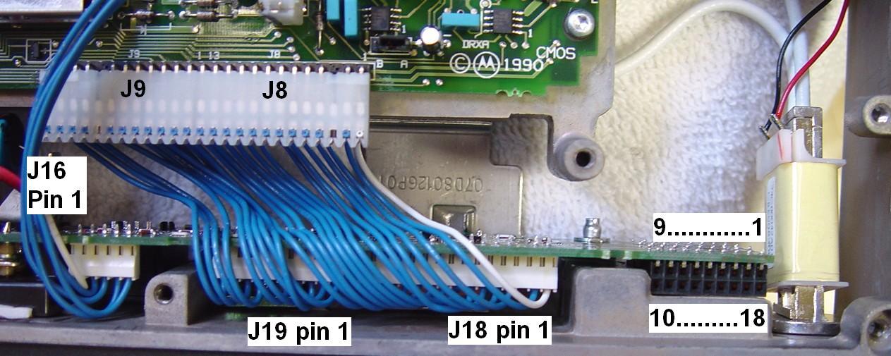
Logic Board (J6/J8/J9) to Front Panel Board (J16/J18/J19):
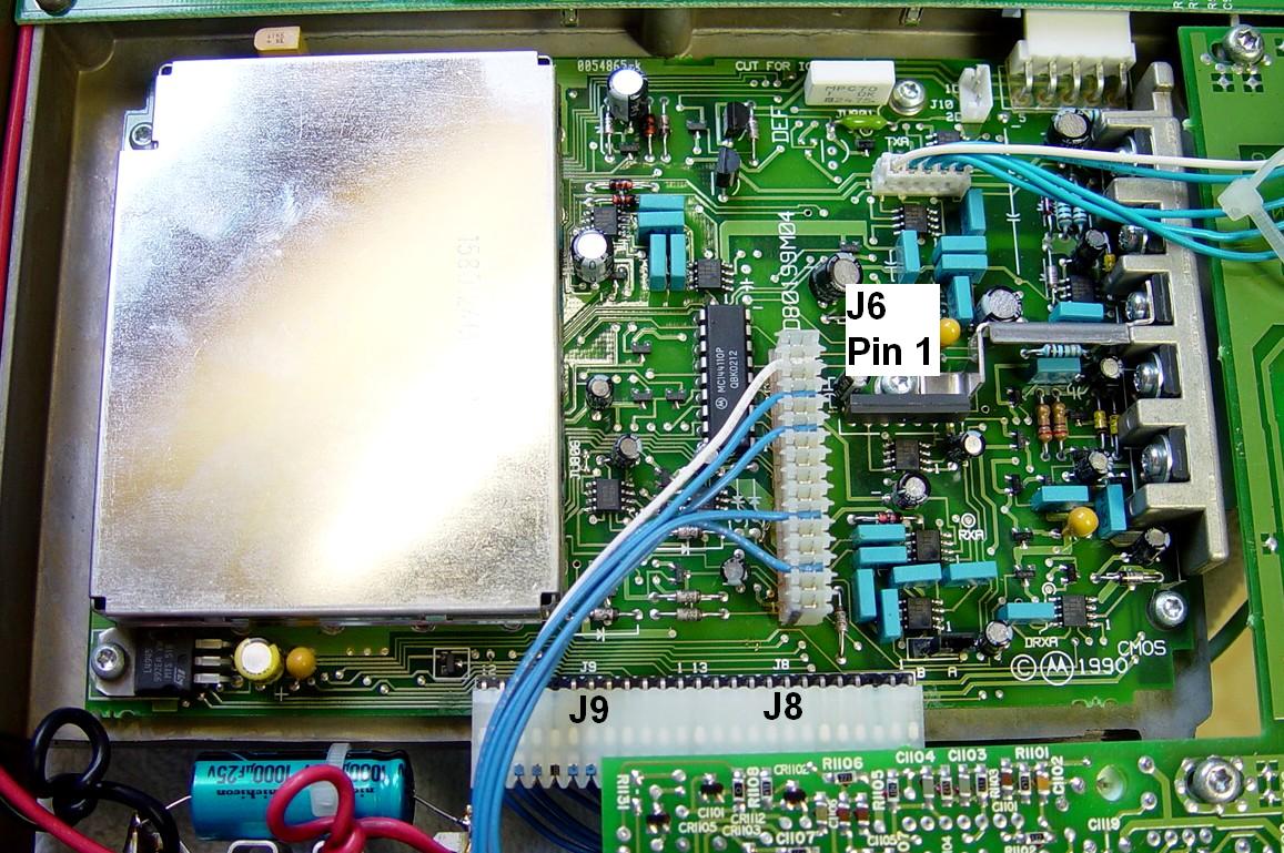
J8 and J9 on the front edge of the logic board are the connectors that would normally go to the control head on MaxTrac radios. In the MaraTrac, one single 25-pin connector plugs into the logic board, rather than the two smaller ones used in the MaxTracs. J6 on the logic board connects to the RF board on the top of the radio. The pins on this connector are longer than normal and extend above the logic board to accept that additional connector, which runs to J16. J16, J18, and J19 are on the front panel board and can be seen in the Option Connector photo above this one. These wires are permanently attached to the front panel board. When viewed from the under the front of the radio with the antenna relay at the right, J16 is numbered left to right, while J18 and J19 are numbered right to left. The majority of these signals go directly to the connectors listed above.
| J6 | J8 | J9 | Signal Name or Use | J16 | J18 | J19 |
|---|---|---|---|---|---|---|
| 1 | --- | --- | 9.6V | 1 | --- | --- |
| 3 | --- | --- | Detected Audio | 2 | --- | --- |
| 5 | --- | --- | VCO Lock | 3 | --- | --- |
| 10 | --- | --- | VCO Modulation | 4 | --- | --- |
| 13 | --- | --- | Reference Modulation | 5 | --- | --- |
| --- | 1 | --- | Volume Control Top | --- | 1 | --- |
| --- | 2 | --- | Volume Control Wiper | --- | 2 | --- |
| --- | 3 | --- | Keyway | --- | 3 | --- |
| --- | 4 | --- | Handset Audio | --- | 4 | --- |
| --- | 5 | --- | Switched B+ | --- | 5 | --- |
| --- | 6 | --- | B+ | --- | 6 | --- |
| --- | 7 | --- | SCI+ | --- | 7 | --- |
| --- | 8 | --- | PB1 (Spare) | --- | 8 | --- |
| --- | 9 | --- | PB2 (Spare) | --- | 9 | --- |
| --- | 10 | --- | Ground | --- | 10 | --- |
| --- | 11 | --- | Push-To-Talk | --- | 11 | --- |
| --- | 12 | --- | Microphone Audio | --- | 12 | --- |
| --- | 13 | --- | Emergency / Hook | --- | 13 | --- |
| --- | --- | 1 | TX / Busy | --- | 14 | --- |
| --- | --- | 2 | Display Enable | --- | 15 | --- |
| --- | --- | 3 | FPD | --- | --- | 1 |
| --- | --- | 4 | FPE | --- | --- | 2 |
| --- | --- | 5 | FPB | --- | --- | 3 |
| --- | --- | 6 | FPC | --- | --- | 4 |
| --- | --- | 7 | FPA | --- | --- | 5 |
| --- | --- | 8 | Keyway | --- | --- | 6 |
| --- | --- | 9 | 5VDC | --- | --- | 7 |
| --- | --- | 10 | Serial Data | --- | --- | 8 |
| --- | --- | 11 | Serial Clock | --- | --- | 9 |
| --- | --- | 12 | Ground | --- | --- | 10 |
Details of Individual Repeater Controller Signals:
Power is obviously required. You will need a source of A+, between 13 and 14 volts DC. It must feed the big red wire on the transmit radio as well as the B+ input of both radios. Of course, the repeater controller will also need it. Fuses are recommended for each device.
Ground is simple. Use the big black wire coming out of the control cable. You must also supply a ground to the Power On/Off control line to activate the power relay inside the radio. You will probably also have ground via the RF coax connections. If you mount the radios with their mounting brackets, that will provide a ground to the chassis, but don't rely on that connection, because you may have to work on the radio on the bench without the bracket. Make sure your power supply negative is also connected to the station ground. If you end up interfacing your controller via the RJ45 programming jack, use the ground pin here as well.
Transmit Audio from the controller can go into the MIC High input in a variety of places, such as the control cable connector, the RJ45 programming jack, or the Option jack. Use a 10uF 16V electrolytic capacitor in series with this line, with the positive end towards the radio. Some repeater controllers may already have a capacitor in series with their input line.
Push-To-Talk from the controller can go into the PTT input in a variety of places, such as the control cable connector, the RJ45 programming jack, or the Option jack.
Receive Audio to the controller can be found in several places as well. You can get it on the RJ45 programming jack and the Option jack, but it's also the same signal that you'd find on the top of the Volume control, available at the control cable connector, the Option jack, on J8 on the logic board, and J18 on the front panel board. All of these are constant level, unaffected by the control head's volume control. This audio is also de-emphasized and the PL/DPL has been filtered out of it, just as it is on the MaxTracs. If DC is present on this line, use a 10uF 16V electrolytic capacitor in series, with the positive end towards the radio. Some repeater controllers may already have a capacitor in series with their output line.
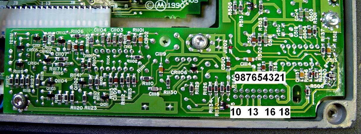
Carrier Indication (COR) is the remaining signal. There are several points that change state when merely a carrier is detected: Channel Activity and Squelch Decision on the Audio/Squelch board for example, but if your repeater will be using coded squelch (PL or DPL), you will want a signal that's active only when the proper code is received. The Audio PA Mute signal is what I use on MaxTracs, and it already feeds the MaraTrac's logic board, but not at a level most repeater controllers can readily use.
The source for the Audio PA Mute signal is on the radio's logic board, underneath the bottom plate, under the microprocessor shield. The feed-through hole near the big IC has a very nice signal that's 5V when a properly encoded carrier is received. One method of accessing it would be to add a resistor and transistor inverter to the logic board and bring this open-collector COR signal to J8 pin 8 (PB1, a spare signal), then add a jumper on the front panel board to get the signal from J18 pin 8 to the spare pin on the Option board (J21 pin 12) or to the RJ45 programming connector (J20 pin 2). This gives you an active-low COR signal for your repeater controller. Your controller will need a pull-up resistor on this line; some units may already have one or provide for it. DO NOT put the resistor inside the receive radio, because if that radio loses power, it will pull the COR line down to ground and the controller will think there's a valid carrier present. I've added this circuit to a lot of MaxTracs; it's simple, works great, and avoids using the accessory jack. See the related article on Repeater-Builder about Simple MaxTrac Interfacing.
Another version of the Audio PA Mute signal from the logic board feeds the base of a transistor (Q500) on the Audio/Squelch board, and the voltage change at that point (0V to 0.7V) is insufficient for further use. The collector of that transistor goes from about 2.3V when squelched to 0V when a valid signal is being received. Unfortunately that level is insufficient for external controller use and as it turns the audio amplifiers on and off, you can't load it down very much. The audio amplifier outputs (U501 pin 4 and U502 pin 4) change from 0V when squelched to 6.3V when a valid signal is being received, however there's also speaker audio present on these lines. Chances are, you'll have the speaker volume turned all the way down at the repeater site, and unless you run it up to an excessive level, the audio won't bother you too much.
I've seen a couple of interface schemes that instruct the user to connect Q500's collector to the Emergency / Hook line, J1 pin 18. This pin goes to the logic board where it is pulled high, so unless you disconnect the existing wire, you're likely to damage the audio output circuit. I wouldn't risk it. If you free up J1 pin 18, you might as well add the two-component inverter and get a real COR signal out of the radio.
Given a choice, I'd recommend adding the resistor and transistor to the logic board and bring it out to either the Option Connector or the Programming Connector.
Microphone Hang-Up Signal:
This one is hard. You need to ground the Hang-Up signal if you want to use coded squelch on the receive radio. Even though there's a dedicated pin on the control cable connector, it's not used for this function at all. All of the control heads (advanced, clamshell, hand-held) route this input signal to a parallel-to-serial shift register, where other control head buttons get mixed in and sent to the radio as individual bits along a single serial data line. If you leave a control head attached, you can ground the Hang-Up signal on the back of the head and you're good to go. If you don't want to permanently utilize a control head, your only recourse is to wire up a CD4021B shift register IC and duplicate the support circuitry present in any control head, which includes connecting the serial clock and data lines, the Display Enable line (which may need a transistor to invert it), terminating the unused inputs to +5V through a single 4.7k resistor, and grounding the appropriate pin for the Hang-Up signal. Look at any of the control head schematics to find which input you need to ground. The programming software doesn't give you an option to disregard this signal, like you can do on a MaxTrac. If you connect this Hang-Up signal to your repeater controller, you can enable coded squelch by bringing this line low, or disable coded squelch (i.e. use just carrier squelch) by bringing this line high.A Common Interface Point:
Given the limited number of choices and ease of access, I'd recommend using the Programming jacks on both the receiver and transmitter for your controller interfacing once you add this COR signal to it. This connector would then have signals as noted in the table below. You would make up two RJ45 cables between your controller and the two radios, wired as follows. You don't need very many wires; a single shielded pair would do nicely; connect the shield to ground. Even flat 8-conductor network cable will do the job, as long as you keep your cable length short (less than a few feet).
| Pin | Signal Name or Use | RX Radio | TX Radio | Notes |
|---|---|---|---|---|
| 1 | Switched B+ | - - - - - | - - - - - | |
| 2 | COR Output | RX COR | - - - - - | Use external pull-up resistor |
| 3 | Emergency / Hook | - - - - - | - - - - - | Can't be used for this purpose |
| 4 | Ground | Ground | Ground | |
| 5 | Microphone Audio In | - - - - - | TX Audio | Use external isolation capacitor |
| 6 | Push-To-Talk Input | - - - - - | TX PTT | |
| 7 | SCI+ | - - - - - | - - - - - | |
| 8 | Handset Audio Out | RX Audio | - - - - - |
I've used this wiring configuration for several MaxTrac-based repeaters and it works very well. I'd also recommend programming the radios with identical frequencies and making the same modifications to BOTH radios so you can swap them around if needed.
Configuring the Radio:
Obviously you have to get the radio to power up, and there's probably no reason to have a control head attached to each one. Ideally, you would have a pair of extra control cables from a MaraTrac, Mitrek, Mocom 70, or Motrac. Surprisingly, these all have similar wiring and signal/pin usage. Could Motorola actually have standardized something this simple?
Apply +13VDC from a supply capable of handling 25 amps to the front control cable connector pins 19 and 4, and apply ground to pins 17 and 13. If you're going to leave the top cover off the radio, you could just solder some heavy wires directly to pins 17 and 19 (there are already heavy black and red wires attached there) and add thin jumpers to the other two pins. While this did cause the radio to turn on, all I got was a ticking sound out of the loudspeaker and the receiver did not seem to be listening to the channel I expected it to be on. Further investigation shows that there is no receive audio path through the missing control head so the radio has no audio to amplify, hence the ticking sound. Also, the radio could have powered up on any random mode.
Delete any and all scan lists, phone lists, zones, and MPL lists. Make sure all remnants of those features are gone. Delete all modes from the radio except one, and make sure that's the "home" mode. Program that for your repeater pair. You should program both radios with the same information. All you want are transmit and receive frequencies and PL/DPL codes, nothing else.
Disable the Audible Tones (audio beeps that are confirmation of control head button presses) on the Radio-wide screen, otherwise any time you press a button the audio will un-mute and the repeater will think a carrier just came in.
Set the transmit power no higher than half the rated output power. Set the timeout timer to 000 seconds (and consider adding manual power control). Again, do this to both radios.
I've read that if your radio is configured for an advanced (A7) control head, you could configure the radio to use the standard clamshell control head and disconnect the advanced control head, but if you ever reconnect the advanced head in the future, you might "brick" the radio. I have not confirmed this. I have also not yet successfully powered up a MaraTrac without an advanced control head. Lee N3LEE reports that you CAN disconnect the head and reconfigure the radio.
One item remains: dealing with the Hang-Up Box (HUB). This signal has to be grounded to put the receiver into coded squelch mode. This line goes into the control head (all versions) where it's sent to the radio on the serial data line, along with the other button and switch inputs. When a control head is attached, this is not a problem as you can solder a jumper wire from the HUB line to ground inside the head, from pin 23 to pin 40 on the 50-pin control cable connector on the back of the A7 head. (A similar jumper can be added for other heads; the wiring diagrams are in the service manuals.) Leaving a control head connected to the receive radio may be a "Martha Stewart Good Thing" as it lets you monitor the received signal and even disable the coded squelch if you ever have to. Even though the Hang-Up line also appears on the main radio connector J1 pin 18 and the RJ45 programming jack J20 pin 3 (Emergency / Hook), it doesn't seem to perform this function. It runs right into the Hang-up input on the logic board however.
Scott N3XCC reported all sorts of odd behavior on his radios when he disconnected the clamshell control head. He connected "Data IN" pin 8 to "Switched 5V" pin 10 on the radio's control cable connector to eliminate the problem. I suspect the radio was not happy with this line floating. Not all radios will need this, but it's good engineering practice to terminate all unused signals to either +5V or ground.
You could duplicate the shift register U1001 circuitry on the clamshell control head, which would then give you control of the microphone Hang-Up input, the Talk-Around switch input, the Squelch Disable (Monitor) switch input, the Zone/Scan switch input, and the three channel-select switch inputs. The chip is an MC4021 / CD4021BC / 87K36 8-stage static shift register with parallel input, serial output, and is a 16-pin DIP.
Acknowledgements and Credits:
All of the signal information, including circuit board X-ray views and cabling diagrams, was found in either the MaraTrac Low Band Instruction Manual, 6880102W95, or the M400 Service Manual, 6880901Z56; both can be found on the repeater-builder web site as large PDF files. Additional information came from the MaraTrac Remote Squelch Supplement, also now available on this web site. Verification then came from personal inspection with test equipment.
Disclaimer:
I have NOT performed any of these modifications or procedures myself, nor have I tried to use a MaraTrac in repeater service (MaxTracs: yes), so there may be some fine-tuning of this article as time goes on. There may also be other interface points that I am not aware of. If you have additional info based on personal experience, please let me know and I'll add it.
User Experiences:
Mark KC8QVX operates a two-meter IRLP-equipped repeater in Jonesville MI using a
MaraTrac radio as a transmitter. He reports
There is a QSO party on New Year's Eve and during the 2011 celebration my transmitter was up for 17 hours. There were a few three-minute idle times but other than that the transmitter was keyed up 100% of the time. I mounted two four inch 12 volt DC muffin fans under the heat sink. I used the 9.6 volts from the antenna relay to activate a separate 12 volt relay to run the fans. Any time the radio is transmitting the fans are running, and because they come on at the start of a user's transmission it never gets hot. I have run this transmitter for 2 years on the New Year's Eve QSO party and it is still running fine. I will also mention that it is putting out 100 watts and giving me 70 watts out of the duplexer.
Contact Information:
The author can be contacted at: his-callsign [ at ] comcast [ dot ] net.
Back to the top of the page
Up one level (MaraTrac index)
Back to Home
This article was conceived October, 2010 and first posted 02-Dec-10.
Article text, photos, artistic layout, and hand-coded HTML © Copyright 2010 by Robert W. Meister WA1MIK.
This web page, this web site, the information presented in and on its pages and in these modifications and conversions is © Copyrighted 1995 and (date of last update) by Kevin Custer W3KKC and multiple originating authors. All Rights Reserved, including that of paper and web publication elsewhere.