Back to Home
Remote Squelch Pot
By Robert W. Meister WA1MIK

|
MaraTrac index Back to Home |
Activating the MaraTrac Remote Squelch Pot By Robert W. Meister WA1MIK |
|
It seems there are a bunch of low-band MaraTracs on the used market these days that are coming through with the HCN1090A remote squelch control head, yet the remote squelch pot doesn't work and radio doesn't seem to know it's there. So far, two people have contacted me about this issue. Dave N1OFJ determined the problem was in the radio (rather than the control head or control cable) and he fixed his after tracing the remote squelch pot line starting at the front of the radio. It turns out that a single jumper is all his needed.
Click on any image below for a larger view.
Jumpers To The Rescue:
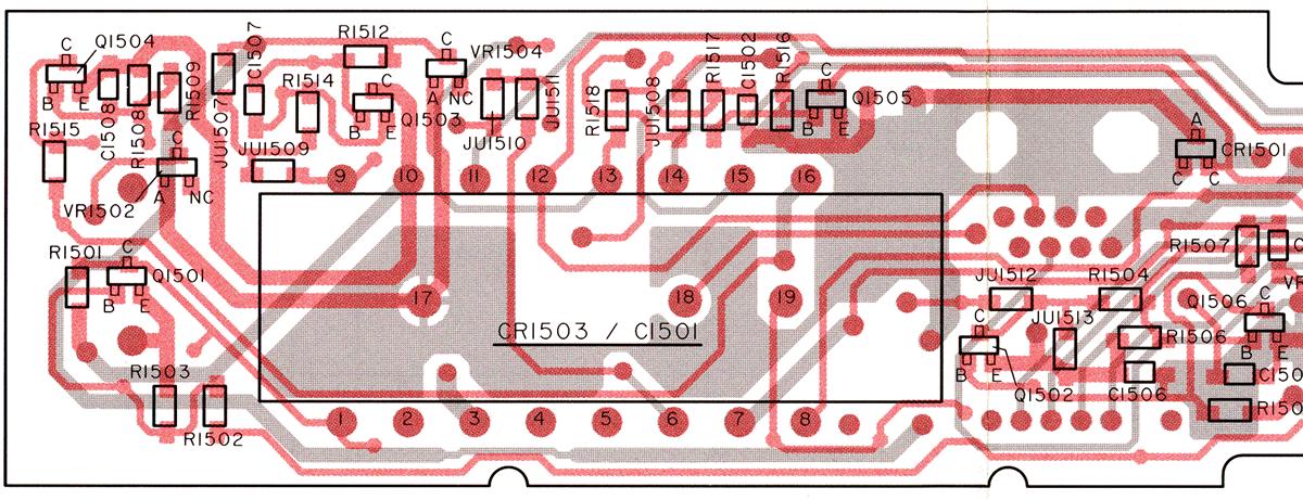
The remote squelch feature is only available on radios equipped with "SP01" versions of the audio/squelch and interconnect boards. It also requires the HCN1090A advanced control head with remote squelch. There's a jumper table (covering JU1509 thru JU1513) on the schematic for the front interconnect board that shows how the jumpers should be configured for remote squelch. These can be seen in the upper right corner of the partial schematic below.

Only two jumpers have alternate positions: JU1509 and JU1510; the rest are always in the same position regardless of remote squelch pot or not. These jumpers are all on the back (inside surface) of the main interconnect board; that's the board that the control cable plugs into and it's located immediately behind and inside the front of the radio. The photo below was taken from the top inside of the radio; it shows the location of several visible jumpers that are above the control cable connector.

A piece of the interconnect board X-ray view is shown below, in case you can't read the jumper marking on the actual circuit board.
You need to check for No Jumper at JU1509 and an Installed Jumper at JU1510. These jumpers are surface-mount zero-ohm resistors marked "000". If your radio has JU1509 installed, remove it. If your radio is missing JU1510, just solder a short piece of wire across the pads.
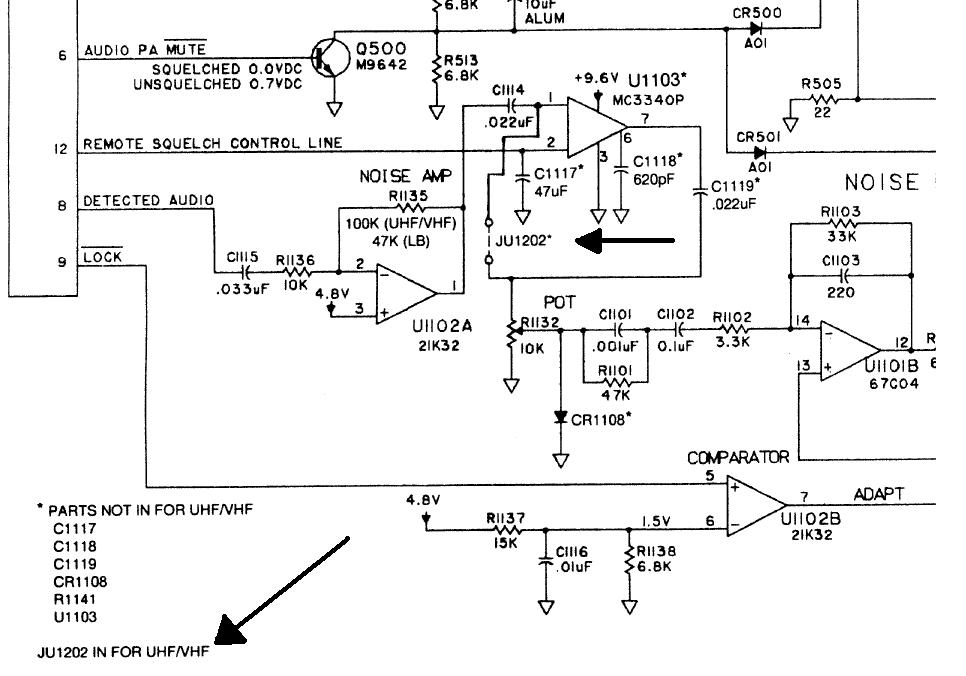
There's also one jumper on tha SP01 audio/squelch board that you need to verify. It's on the underside of the radio. If the 8-pin IC U1103 is NOT installed, JU1202 MUST BE installed to complete the squelch noise path around the missing IC. The schematic below shows this jumper and the notes in the bottom left corner that indicate which parts are present or not.
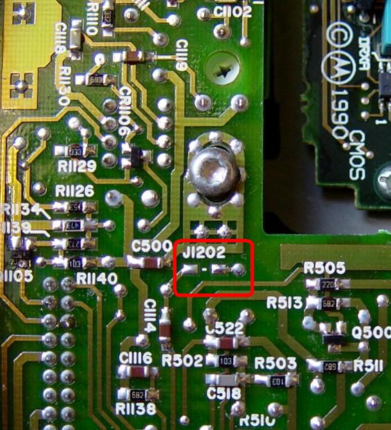
The jumper location is very close to the inside corner of the audio/squelch board. Here's a photo of a 42-50 MHz board without the J1202 jumper, which is how it must be for the remote squelch to operate correctly. Note that the silk-screen on the SP01 board shows J1202, not JU1202.
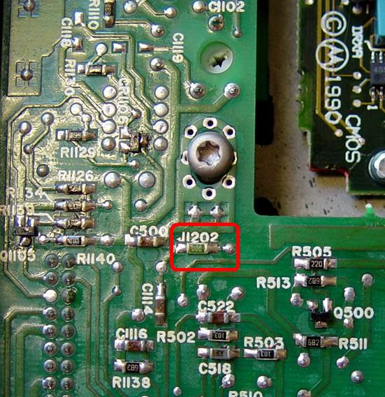
I have a 29-36 MHz Maratrac that has the SP01 board installed but the IC and other parts are missing, so the jumper J1202 IS present and remote squelch is not available. Here's a photo of the board configured for no remote squelch. Note that the squelch pot on the board is still used to adjust the radio's squelch.
Adjusting The Squelch:
After installing JU1510, you'll probably have to readjust the squelch pot on the audio/squelch board; it's the only pot on that board and it's shown in the photo below.

The procedure in the manual is rather complicated. I recommend setting the pot on the control head to the nine-o'clock position, then adjusting the pot on the audio/squelch board so the squelch is just closed. Do this with the radio connected to the antenna it will be used with, since the noise level will be higher than it would be on the bench.
How It Works:
Detected audio is fed into U1103 pin 1. The remote squelch pot on the control head pulls down U1103 pin 2 as the pot is rotated clockwise (tighter squelch). This increases the gain of U1103 and its output at pin 7 is fed to the internal squelch pot on the audio/squelch board. Increasing the signal is equivalent to more noise, so the squelch circuit closes. As the noise amplitude decreases, the squelch can open. Thus you essentially have two squelch pots in series. On many older radios with remote heads such as the Motrac and Micor, detected audio was fed up to the control head where it went to both the audio volume control and the squelch pot. The arms of both pots brought these signals back down to the radio chassis where they went their separate ways.
Real Part Numbers:
The audio/squelch board documentation only lists Motorola house part numbers for the ICs. In case you should need to replace one, U1101 is an RC4136N or RV4136N quad op-amp, U1102 is an MC3303P quad op-amp, which is equivalent to an LM324, and U1103 is an MC3340P electronic attenuator. This was verified on at least four different MaraTrac radios.
Acknowledgements and Credits:
Thanks go to Dave N1OFJ for doing the initial investigation work on his radio.
Schematic and X-ray views of the interconnect board came from the service manual revision to the MaraTrac Low-band Service Manual (6880102W95) as FMR-1735A, dated June 1996.
All photographs were taken by the author and are copyrighted by him.
Contact Information:
The author can be contacted at: his-callsign [ at ] comcast [ dot ] net.
Back to the top of the page
Up one level (MaraTrac index)
Back to Home
This page originally posted on Tuesday 06-Oct-2009
Article text, photos, artistic layout, and hand-coded HTML © Copyright 2009 by Robert W. Meister WA1MIK.
This web page, this web site, the information presented in and on its pages and in these modifications and conversions is © Copyrighted 1995 and (date of last update) by Kevin Custer W3KKC and multiple originating authors. All Rights Reserved, including that of paper and web publication elsewhere.