Back to Home
Motorola MaraTrac®
Mobile Radio
By Robert W. Meister WA1MIK
and James G. Kalkowski N1GTL

|
MaraTrac index Back to Home |
A Quick Look at a Motorola MaraTrac® Mobile Radio By Robert W. Meister WA1MIK and James G. Kalkowski N1GTL |
|
Overview:
The MaraTrac is like a MaxTrac on steroids. It's basically the insides of a MaxTrac mobile, without the control panel, mounted in a Mitrek housing. It offers two to three times as much transmitter output power as a MaxTrac and also boasts a 10w audio amplifier that drives both sides of a Spectra-style speaker (same warning applies: do not ground either speaker lead). It also offers up to 99 channels and has a few more features available. All MaraTracs and M400s are remote-mount radios.
MaraTracs are rated for 100 watts on UHF and VHF-HI, and 110 watts on VHF-LO. They cover 403-430, 450-470, 470-494, 494-512 MHz, 136-156, 144-174 MHz, and 29.7-36.0, 36.0-42.0, 42.0-50.0 MHz, the same ranges as MaxTrac RF boards and PAs.
The subject unit was a T74XTA7TA7BK (100w UHF 99 channel) radio with the advanced (A7) control head. The 99-channel limit is due to the two-digit, seven-segment, LED channel display used on some of the control heads. We also borrowed a T81XTA7TA7BK 110w 42-50 MHz mobile radio to show some of the differences.
There's also a very similar radio called a Radius M400. This has exactly the same model numbers as the MaraTrac, and seems to be identical in all other respects except they only came with advanced control heads. I believe the M400 / MaraTrac radios have the same family lineage as the Radius / MaxTrac radios do: basically identical but sold through different channels. Knowing Motorola, you'd probably need two different programming packages too. I obtained an M400 Service manual, 6880901Z56 (No Longer Available in September 2010), that covers all three ranges on low-band, 150-174 MHz VHF, and 450-470 MHz UHF models, all in one manual. I suspect the band limits are expandable to cover the amateur frequencies.
As of January 2011 the MaraTrac radio series are discontinued.
I also discovered the following note in a MaraTrac ordering document: "The following frequencies are not available: 43.200, 158.400, 172.800 MHz." I suspect that there are also some unavailable frequencies in the UHF range. These are due to the receiver picking up internal oscillator signals, something that could happen on a MaxTrac, Radius, or M400 radio as well.
Model Numbers:
The 12-character model number breaks down thusly:
| Case | Power | Band MHz | Series | Channels | Control Head | Version | Package |
|---|---|---|---|---|---|---|---|
| T: Always | 3: 15-30 | 1: 29.7-50 | XTA7: Always | D: 8/16 | A2: clamshell | A: Early | K: Always |
| 4: 30-50 | 3: 136-174 | T: 99 | A3: clamshell w/scan | B: Later | |||
| 7: 100 | 4: 403-512 | A5: HHCH | |||||
| 8: 110 | A7: Advanced |
The programming software has the following model numbers listed within it, in no specific order:
T81XTA7DA2_K, T73XTA7DA2_K, T43XTA7DA2_K, T74XTA7DA2_K, T34XTA7DA2_K, T81XTA7DA3_K, T73XTA7DA3_K, T43XTA7DA3_K, T74XTA7DA3_K, T34XTA7DA3_K, T81XTA7TA5_K, T73XTA7TA5_K, T43XTA7TA5_K, T74XTA7TA5_K, T34XTA7TA5_K, T81XTA7TA7_K, T73XTA7TA7_K, T43XTA7TA7_K, T74XTA7TA7_K, T34XTA7TA7_K.
It also shows the following bands and ranges, not all of which were available:
Low Band Range 1 (22.5-29.7 MHz), Low Band Range 2 (29.7-36.0 MHz), Low Band Range 3 (36.0-42.0 MHz), Low Band Range 4 (42.0-50.0 MHz), VHF Range 1 (136-162 MHz), VHF Range 2 (146-174 MHz), UHF Range 1 (403-430 MHz), UHF Range 2 (450-470 MHz), UHF Range 3 (470-490 MHz), UHF Range 4 (490-512 MHz).
If your radio is fortunate enough to still have another model number sticker on it, one with an "HUBnnnn" number on it (sometimes called a TANAPA number, and I have no idea what that word means; it's Japanese), then that will let you know the band range and whether the radio has remote squelch on it or not. The following list was taken from the manuals; it's very likely there are additional numbers out there, possibly in manual revisions. The low-band M400s use the same HUB numbers as the MaraTracs. The VHF and UHF numbers may be M400-specific. The 3rd letter signifies the frequency band.
| HU? Number | Range | Rem Sq? |
|---|---|---|
| HUB1114A | 29.7-36 | No |
| HUB1115A | 36-42 | No |
| HUB1116A | 42-50 | No |
| HUB1135A | 29.7-36 | Yes |
| HUB1136A | 36-42 | Yes |
| HUB1137A | 42-50 | Yes |
| HUD1730A | 146-174 | No |
| HUE2107A | 450-470 | No |
Manuals and Other Documentation:
The following list, provided by Eric WB6FLY, is as of February 2008 and hasn't changed as of September 2010. Prices are US Dollars. Unfortunately, most of the various radio service/instruction manuals are No Longer Available.
6880102W18 VHF Radio 150-174 MHz, 100 Watts, T73XTA7---AK series (NLA)
6880102W19 Handheld Control Head Operator's Manual $1.61
6880102W20 Advanced Control Head Operating Instructions $1.74
6880102W21 UHF Radio 450-470 MHz, 100 Watts, T74XTA7---AK series $40.16
6880102W22 Basic Operators Manual (Scan and Talkaround) $2.86
6880102W23 Installation Guide $1.74
6880102W24 RSS Manual $29.50
6880102W27 Handset Option B109 (NLA)
6880102W29 Siren/Public Address $17.18
6880102W30 Auxiliary Switch Panel HLN1260A $5.44
6880102W39 Low Band Instruction Manual, T81XTA7---AK series (NLA)
6880102W45 Radio Option B585AF DTMF Decoder Service Manual (NLA)
6880102W47 Radio Option B585AF DTMF Decoder Operator's Card (NLA)
6880102W58 Signaling Manual $5.98
6880102W60 Radio Signaling Options Quick Reference Card $3.61
6880102W63 Notice (NLA)
6880102W87 UHF Radio, 100 Watts, T74XTA7---BK series $42.62
6880102W94 VHF Radio, 100 Watts, T73XTA7---BK series $26.33
6880102W95 Low Band Radio, 110 Watts, T81XTA7---BK series (NLA)
A revision to the 6880102W95 manual covers the "A7 Advanced Control Head with Adjustable Squelch Control." This includes full documentation of the Special Production (SP) audio and interconnect boards inside the radio. This revision came with a manual I recently obtained and is listed as FMR-1735A-1 dated June 1996. Usually these are not available separately from Motorola. The remote squelch was apparently only available on the low-band radios sold after October 1994 and these (so far) are revision "B" radios. See the Remote Squelch section later in this article for more details.
Peeking Inside:
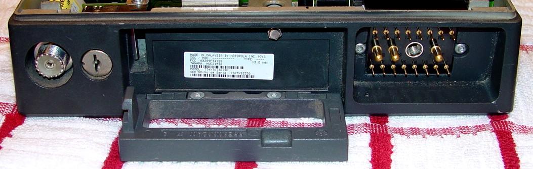
Like a Mitrek, the drawer is unlocked with a standard 2135 key. Pulling the handle down released the bottom mounting plate (same part as for a Mitrek) and exposes the top release. While it looks like you'd twist it with a nut-driver, it's a push-button release. Here's a view of the front of the radio:
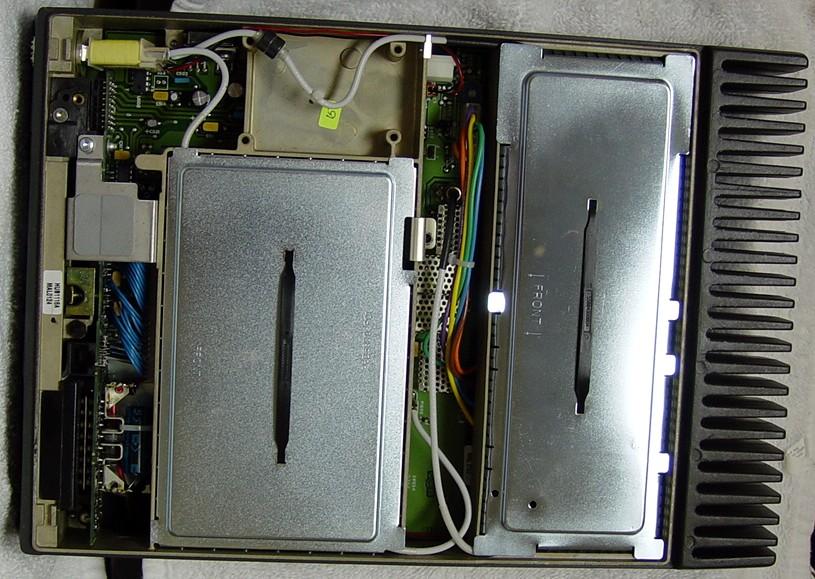
Here's a photo of the inside top of the low-band radio with its shields in place. The UHF radio is similar:
Inside the top we removed a shield over the entire cast-aluminum RF cavity, which exposed a very standard-looking MaxTrac UHF RF board and the VCO shield, which was also easily removed. The usual crystal label and tuning label were present. The RF board's TX output feeds another board that contains the power control circuitry, an amplifier, and some filters; this board feeds the input of the PA; just follow the TX coax cable. The RX coax goes directly to the T/R relay. No surprises here; no solid-state switching (unlike a MaxTrac or Spectra). There was also a shield over the entire PA, which was removed for this photo:

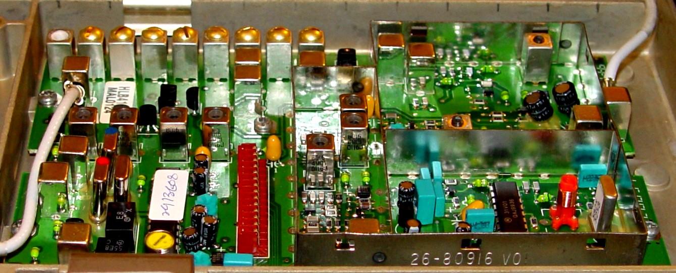
Here's a similar photo of the low-band radio with its RF board and PA shields removed:
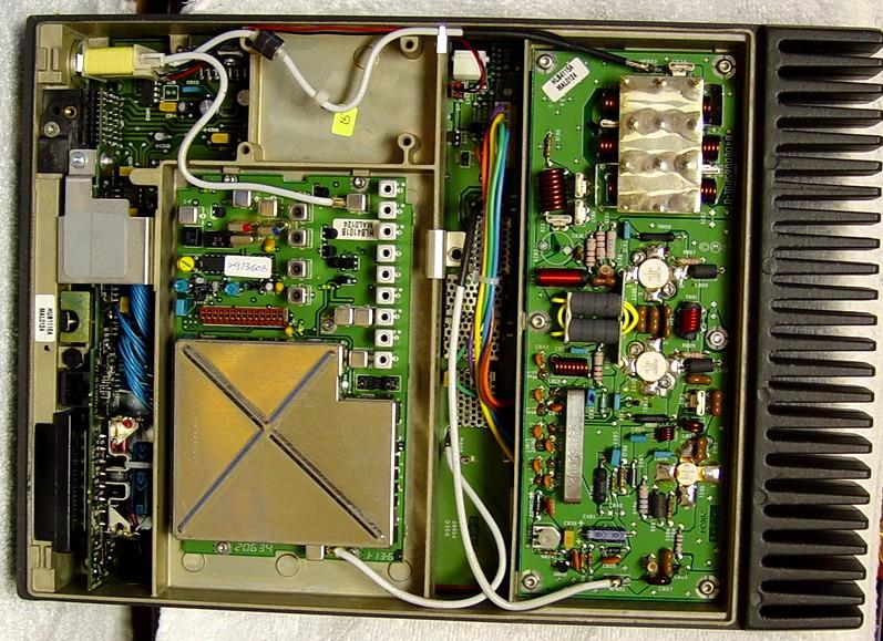
At the front of the radio (left side of the photo) you find the regular Mitrek T/R relay, complete with an SO-239 antenna connector (these radios still use an SO-239 antenna jack for all models), a black RJ45 jack for programming (barely visible, next to the top cover latch hole) which can use a standard two-wire MaxTrac RIB cable (see note below), and the control head / cable interface. The power amplifier (PA) with a very large heat sink is found at the rear of the chassis (right side of the photo). There's another board between the RF board and the PA (the manual calls this the "exciter" that has the power control circuitry, some band-pass filtering, and an intermediate power amplifier (IPA) on it that produces about 2.5 watts to drive the PA.
NOTE: The RJ45 programming jack is wired about the same as what you'd find on a MaxTrac or Radius radio except that +14V is present on pin 1. Make sure the programming cable you use only has pins 4 and 7 connected. It's the same cable as for the MaxTrac, Radius, or GM300 mobile radios. Here's the signal configuration for the MaxTrac front panel MIC jack and MaraTrac programming jack:
| MaxTrac | Pin # | MaraTrac |
|---|---|---|
| Spare | 1 | SW B+ |
| Spare | 2 | Spare |
| Hook | 3 | Emergency |
| Ground | 4 | Ground |
| MIC Audio | 5 | MIC Audio |
| PTT | 6 | PTT |
| Programming | 7 | Programming |
| Headset Audio | 8 | Headset Audio |
Four T15 flat-head screws holding the bottom cover to the radio chassis were removed, allowing us to pry the cover off (it is well gasketed). Underneath was a MaxTrac-style logic board, complete with the shield over the microprocessor area. This unit had a 5-pin (accessory connector) board. There was nothing plugged into the speaker jack and in fact you can't get speaker audio off the logic board; some parts are missing. A few wires were attached to a connector that fits over the 14-pin plug going through the chassis to the RF board. An L-shaped audio/squelch and interface board fits into the space around the bottom of the unit. Those big silver covers next to the black PA heat sink are filter shields.
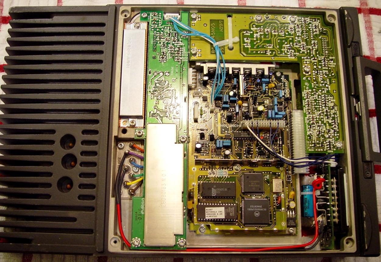
The logic board is an HLN5402C. The firmware on one low-band radio was part number HLN5372C, Version 5.05, contained in an M27C512-12FI EPROM. The EEPROM next to it is an X2816CPI-20 and it only occupies 24 of the possible 28 holes in the board.
Control Cables:
The radio-end of the control cable uses the same connector that was first used on the early 1960s GGV radio, then the Motrac, Motran, Mocom-70, and Mitrek: a big plastic housing surrounding a captive threaded locking screw, three huge power pins (the heritage of the 6V/12V conversion era), and 16 smaller pins in two rows around the outer edge. There are no spare/unused pins available in this connector. This cable has a short, black, heavy-gauge, negative power lead and a long, fused, red, heavy-gauge, positive power lead coming out of it, along with the control head cable; standard configuration for Mitrek and earlier radios. The normal configuration of the radio has the large red wire only used to power the transmitter RF PA. These radios require 20-22 amps at 14VDC negative ground. An Astron RS-35 will more than adequately power any MaraTrac radio.
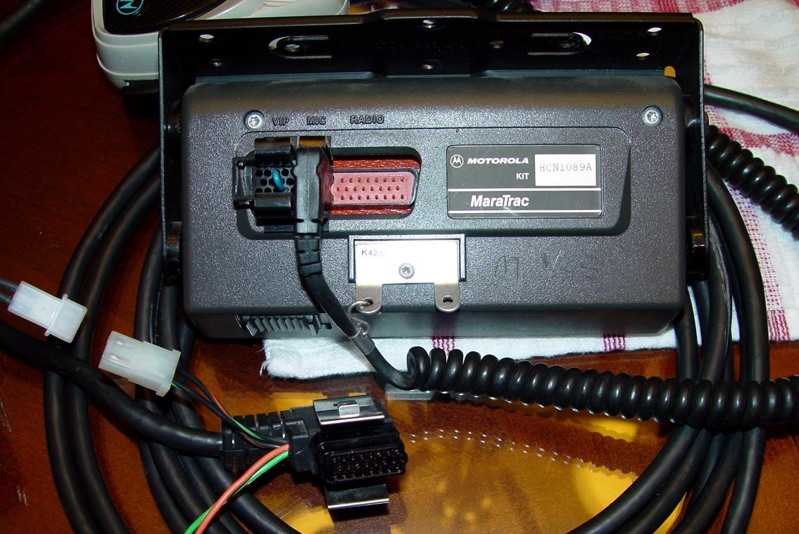
The control head end of the cable was terminated in what seems to be the same three-row connector as on some remote-mount high-power Spectra radios. Also coming out of this end were the usual orange and green ignition wires plus a Spectra-style two-pin Molex speaker connector. We got the radio to receive, for the photos below, by connecting the orange and green ignition wires to the positive terminal of a small power supply, and the big black wire to the negative terminal of the same power supply. The photo of the back of the control head shows the HKN4321A control cable, which is used with an A7 head.
NOTE: The service manuals specify an HKN4321A cable for A7 head configurations. However that part number is not available. An HKN4321B cable is the one currently being sold. A call to Motorola Parts ID confirmed that the 4321A and 4321B are the same cable and they are fully interchangeable. The suffix letter is something used internally by Motorola and has no bearing on the actual end product.
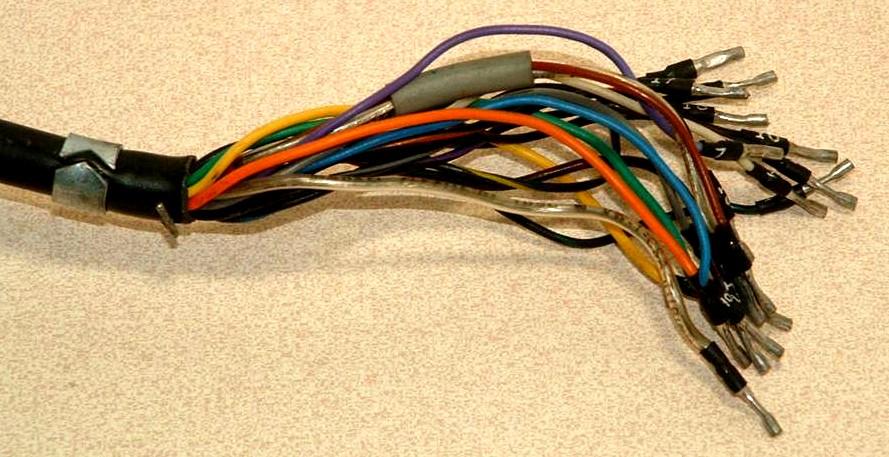
The clamshell (A2 and A3) control heads and cable use individual numbered round pins, rather than a three-row connector, similar to the Motrac control head. Also, the speaker has two matching pins, rather than the Spectra-style Molex connector. The microphone connector for the clamshell head is a MICOR-style rectangular plug and a MICOR mike will work fine with the MaraTrac A2/A3 head. Here's the control-head end of such a cable, HKN4017A (photo from the web):
The hand-held (A5) control head uses a totally different connection scheme. There are several connectors at the head end: one for the speaker, one for the optional siren, one for the emergency switch, one for the hang-up box, and of course one for the actual control head (which contains the microphone).
Speaking of fuses and those orange and green ignition control wires, the green wire is supposed to be connected to the vehicle's battery and remain powered all the time. This maintains the memorized items like mode, volume, and scan. The orange wire should be connected to a conveniently switched power source - such as the ignition switch - or the vehicle's battery. The majority of the radio - everything except the 110-watt power amplifier - operates through this circuit. The big red wire that goes directly from the radio to the battery should have a 40 amp fuse in series with it. There should never be a switch in this high-current circuit.
The values (in Amps) of the fuses in series with the green and orange wires are mentioned in one of the installation diagrams. They've been summarized in the table below.
| Control Head Type | Green | Orange |
|---|---|---|
| Basic (clamshell) 8/16 channel | 7 | 1.5 |
| Hand-Held (HHCH) 99 channel | 5 | 1.5 |
| Advanced 99 channel | 5 | 5 |
Control Heads and Accessories:
The speaker is the same as would be used on a Spectra. The microphone plugged into the back of the head, just like what would be done on a Spectra A9 head, and it used the same 6-pin connector. A VIP port plug with a jumper wire was installed in this unit. Along the bottom of the head was a slide switch that turned the radio on and off. Here's a view of the rear of the control head plus the head end of the control cable:
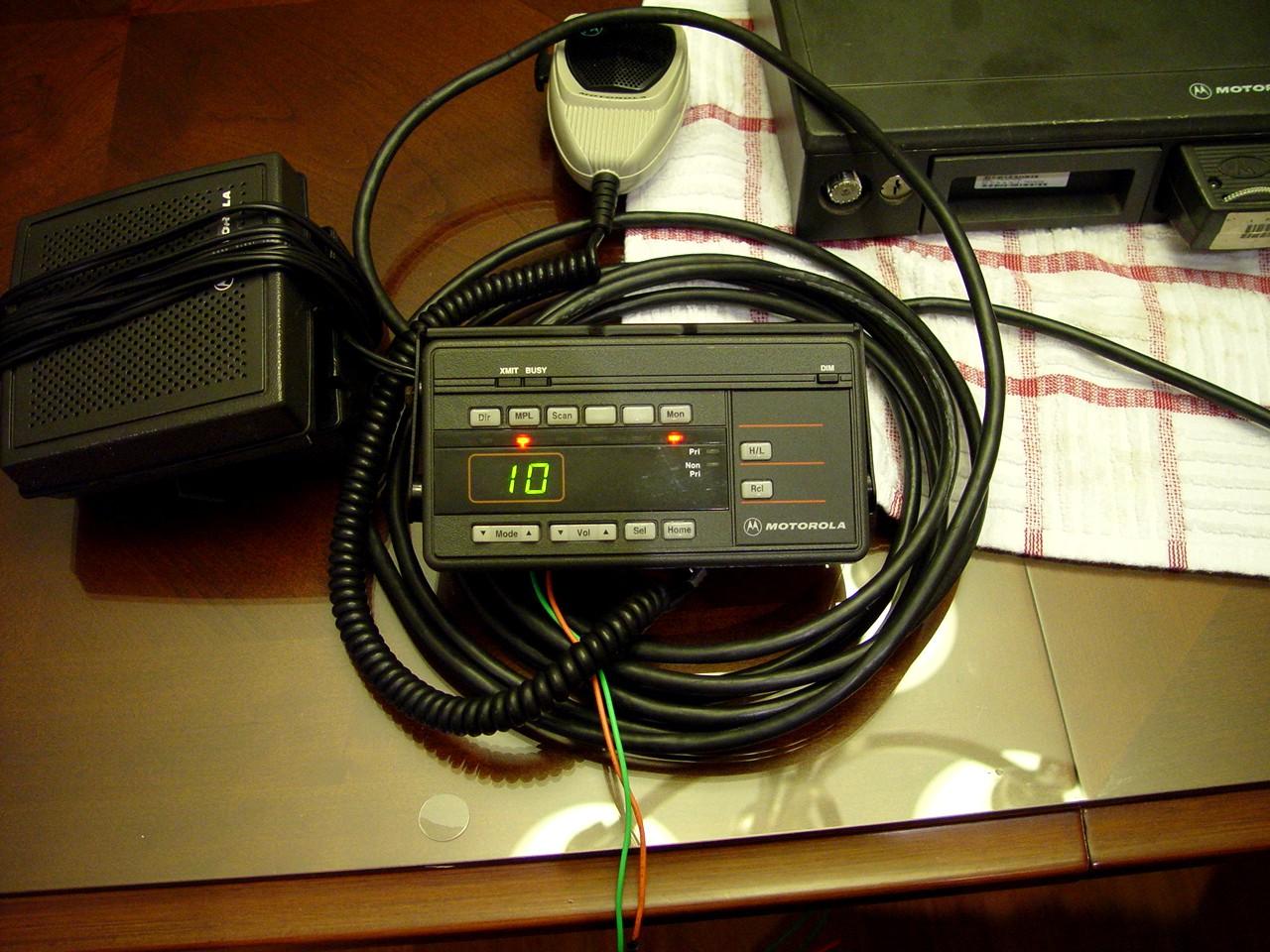
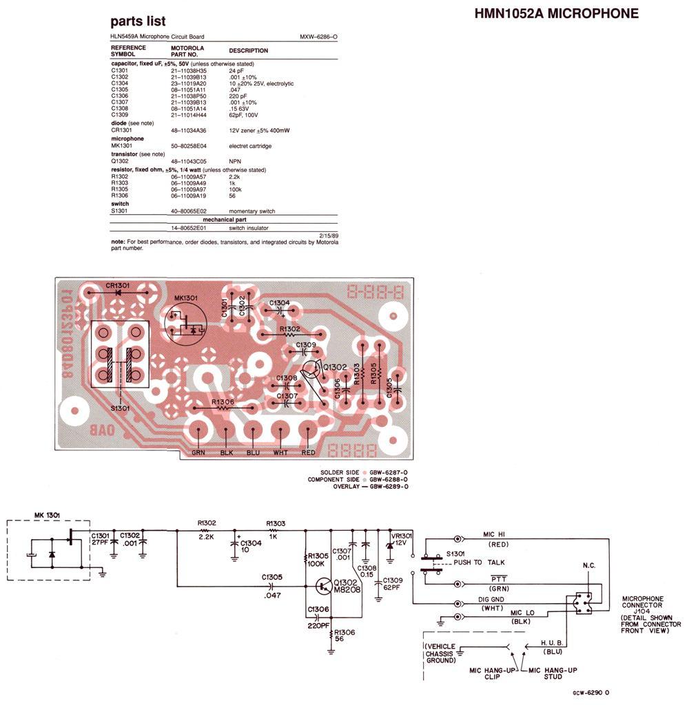
This radio had the advanced control head that resembles the Syntor or Spectra A9 head without the 12 DTMF buttons. The two-digit display is the same green color like on MaxTracs, but all the buttons operate like they would on a Spectra A9 head. Pressing the VOL up/down rocker adjusts the volume, but there's no indication of the position of it, like there is on a Spectra. There are several LED indicators and the two-digit display for channels 1-99. The buttons are lit from the back, and the intensity of the display, including the backlighting of the buttons, can be changed with the DIM button, again similar to a Spectra. Here's a photo of the head (model HCN1089A) and accessories (a normal HMN1061A microphone is shown and you can view the schematic and circuit board layout of the similar HMN1052A mike here; the HMN1022 is a DTMF microphone for the MaraTrac):
Some (later-model) low-band radios have a remotely adjustable squelch circuit. The squelch knob is seen here along the top of this control head (model HCN1090A):

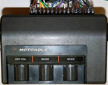
I've seen other MaraTracs with a "clamshell" style control head (model HCN4034B); it has a rotary power / volume knob, a rotary channel selector (1-8), and one more rotary switch that can handle one option: Scan On/Off or Zone A/B. A MON pushbutton switch (not visible) is found along the front edge of the head, and a Talk-Around switch, which would be located to the right of the Scan/Zone knob, is an option. The photo of an 8-channel clamshell head below was found on the web. Note the individual numbered pins on the control head cable that plug into the rear of this head.
I've also seen a Spectra-style HHCH interfaced to one of these, designated as an A5 model number. The programming software identifies four control head types: a Syntor/Spectra 99-channel A9-style with scan, a Spectra 99-channel HHCH-style without scan, an 8-channel clamshell style with scan, and an 8/16-channel clamshell style without scan. Any of these can be found on any radio. All radios are capable of 99-channel operation with a non-clamshell style control head.
If you connect your advanced head and cable to a new (to you) radio and it powers up but the head appears to be dead (no lights, no buttons work), the radio is probably configured for some other head type, probably clamshell. Connect the radio to your programming computer, read and save the existing code plug, then go to the Service Menu (F2) and Change the Head Type (F7) to Advanced (A7) head, then save the code plug back out to the radio. I had this happen with a 29-36 MHz radio, and once I changed the head type, the advanced head worked just as it should have.
Note that the M400 models can only use the Advanced (A7) control head.
Powering It Up:
We only had to connect the orange and green wires plus the big black power wire to a power supply to get it to light up. We never had to use the big red power wire, which only feeds the power amplifier. The green wire powers the receiver; the orange wire enables the transmitter (which allows a mobile installation to use the ignition key as a "transmit enable" switch simply by connecting the orange wire to a switched circuit). Here's a photo of the advanced (A7) control head. The radio was actually receiving a signal at the time I snapped the photo. I had already pressed the MPL and MON buttons just to get something to light up.
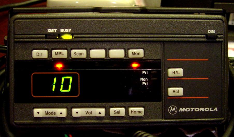
On this particular display, there are buttons for the following functions:
There are also red LED indicators underneath the following buttons. They show an active condition for: Dir, MPL, Scan, Option, VIP, Mon. Next to the H/L and Rcl buttons are amber LEDs for Pri and Non-Pri scanning. There's a red XMIT and an amber BUSY LED above the pushbuttons near the top of the control head.
Out-Of-Band Programming:
The MaraTrac uses RVN-4023/4024 RSS. The M400 uses HVN-9774 RSS. Both of these are, of course, different from what the MaxTrac and Radius use. On the version of software I used, you can not use the SHIFT-NUM method to enter out-of-band frequencies; you need to modify the programming software with a hex editor. The MARATRAC.EXE file in the latest release of the software (R05.00.00g dated 20-Dec-96) can be hex-edited to allow entry of amateur frequencies. The values are all 16-bit decimal numbers in 100 kHz increments (i.e. 440.0 MHz is entered as 4400, then converted to hex: 1130, then the bytes are flipped: 3011). The following table, provided by Bruce KC7GR, shows the hex locations, the original values (hex and decimal), and the new values (hex and decimal) that need to be modified. The hex values are already flipped, ready to enter into the file. Remember that there's an implied decimal point before the last decimal digit. Also note that not all values are on word boundaries. As always, before modifying any file, make a backup of the original.
The first group of entries extends the 29.7-36 MHz range down to 28.1 MHz. The second group of entries extends the 42-50 MHz range up to 54.0 MHz. The third group of entries extends the 450-470 MHz range down to 440.0 MHz. Apparently the software already allows frequency entry down to 144 MHz for the 146-174 MHz range.
| Hex Addr | Original | New | ||
|---|---|---|---|---|
| Hex | Dec | Hex | Dec | |
| 53EC8 | 2901 | 297 | 1901 | 281 |
| 53F09 | 2901 | 297 | 1901 | 281 |
| 567E8 | 2901 | 297 | 1901 | 281 |
| 56829 | 2901 | 297 | 1901 | 281 |
| 42C27 | F401 | 500 | 1C02 | 540 |
| 42C7A | F401 | 500 | 1C02 | 540 |
| 53EF6 | F401 | 500 | 1C02 | 540 |
| 56816 | F401 | 500 | 1C02 | 540 |
| 53F4C | 9411 | 4500 | 3011 | 4400 |
| 5686C | 9411 | 4500 | 3011 | 4400 |
| 56FDC | 9411 | 4500 | 3011 | 4400 |
Converting a 42-50 MHz radio to 46-54 MHz operation:
Hex-edit the programming software as detailed above, so you can enter frequencies in the 50-54 MHz range.
See the MaxTrac 46-54 MHz conversion article for more details on the mods performed to the RF board.
Nothing else in the radio needs to be modified. The radio's output power (Watts) and receiver sensitivity (dBm) are shown below. The radio didn't transmit or receive above 50 MHz originally because VCO didn't lock. The output power was also turned down to 100 watts for these tests; when first received it was making in excess of 150 watts on 45.4 MHz.
| Freq MHz | Before | After | ||
|---|---|---|---|---|
| W | dBm | W | dBm | |
| 45.4 | 100 | -117 | 100 | -108 |
| 46 | 100 | -117 | 100 | -111 |
| 48 | 90 | -117 | 90 | -115 |
| 50 | 80 | -117 | 80 | -116 |
| 52 | 00 | --- | 92 | -116 |
| 54 | 00 | --- | 94 | -115 |
Internal Adjustments:
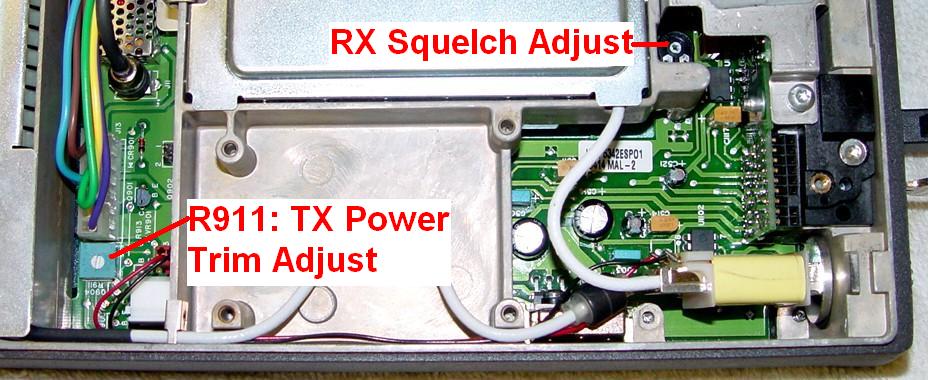
There are two potentiometers worthy of note inside the radio. One trims the transmitter output power, the other adjusts the receiver squelch. There are procedures given for each one, but they're spread out among the service manual, the installation manual, and the RSS manual. The two pots are located here, as seen with the top cover removed, along the left side of the radio (this is a low-band model with remote squelch; the pots will be in similar locations for other models):
The service manual has this paragraph about the R.F. Power Trim Potentiometer R911:
Normally, potentiometer R911 is left at mid-rotation after TRANSMITTER POWER ALIGNMENT. However, potentiometer R911 may be used to trim transmitter power while the radio is in the vehicle. Antenna loading may require adjustment of R911 to achieve rated power output. Adjust potentiometer R911 clockwise to increase power output and counter-clockwise to decrease power output. Monitor all adjustments with a "thru-line" style wattmeter to measure forward and reflected power flow. If the Output Power requires adjustment of more than +/- 10% to achieve rated output power, check the antenna VSWR.
The squelch setting should be adjusted with the radio connected to its antenna, which may increase the noise level, thus affecting the squelch setting. Select a carrier squelch channel, or remove the microphone from its hang-up bracket, or press the MON button to disable coded squelch. If the control head has the remote squelch control on it, set it to the 9 o'clock position. Adjust the squelch potentiometer on the Audio/Squelch board inside the front of the radio counter-clockwise until the squelch opens, then clockwise until it just closes. The remote squelch control should be able to open the squelch when turned fully counter-clockwise.
PTT Doesn't Work or The Radio Won't Transmit:
The advanced (A7) control head routes the microphone's PTT signal through a jumper wire on the VIP plug on the back of the head before it makes its way down the control cable to the radio. If the VIP plug or its jumper is missing, the radio may not transmit via the PTT button on the microphone. There is a jumper - JU1004 - on the rear board of the advanced control head that can be installed to take the place of the jumper wire and VIP plug. Any of the MaraTrac service manuals will show you what pins the jumper wire attaches to, or where JU1004 gets installed. The factory uses a small zero-ohm surface-mount resistor but you can just use a piece of wire.
If neither JU1004 or the VIP plug and its jumper wire are installed, the radio will not transmit when you press the PTT button on the microphone. If you happen to have a Motorola mike with an 8-pin modular plug at the end, you can plug that into the modular programming jack inside the radio and use that to verify that the radio does indeed transmit and it's just an issue with the advanced control head and VIP jumper.
I think they did this so the microphone's PTT button can be used to activate the siren or public address (PA) options available for the MaraTrac, rather than key the transmitter.
The hand-held control head (HHCH) has a jumper on the 6-pin Molex connector that must be installed to pass the PTT signal when no siren is attached. It performs the same function as the jumper wire on the advanced head's VIP plug. This doesn't seem to be an issue with the clamshell head.
Miscellaneous Info:
Motorola's installation guides recommend mounting the radio flat on the floor of the vehicle's trunk. They also contain the following CAUTION, quoted here:
"It is not recommended that the radio be mounted vertically with the front connector facing up."
Other than the heat from the PA rising into the rest of the radio, there's no electronic reason we can think of where this would cause a problem. It's certainly the most obvious way to mount the radio in a truck. However, it was pointed out that radios mounted this way are vulnerable to water and dirt getting in through the openings, which is common with construction vehicles. It also exposes the antenna coax to undue wear and tear if anything is stored on top of the radio.
The radio supports talk-around (or direct) by causing the radio to transmit on the receive frequency, if the control head supports it. Not all do.
According to the sales brochure, the low-band radios support a squelch pot on the control head. I've been told that some older low-band radios do not have an external squelch control or the ability to utilize it. The low-band radio loaned to me, as well as three I eventually purchased, did have the remote squelch pot and were revision "B", and two circuit boards inside the radio had "SP01" after the part number, but I later obtained another "B" model that had the later revision board without the remote squelch parts installed. Also, the low-band MaraTracs (and MaxTracs) have a noise-blanker in the receiver, commonly called an "extender" in Motorola lingo. This noise-blanker can be disabled by pressing and holding the "Mon" button until you hear three beeps.
Apparently the programming software doesn't allow the 136-162 MHz range. It also may not allow some other ranges, even though the service manuals show them.
Some MaraTracs can support an external Siren/PA unit, connected via the VIP jack on the rear of the control head or another connector on the control cable. A shorting plug is installed to route the PTT signal from the microphone to the radio when a siren is not attached. I found this was not required on my radio with an A7 head due to an internal configuration jumper, but it IS required with an HHCH.
The radio seems to be a marriage of several technologies: Mocom70 / Motran / Motrac / Mitrek (control cable connector / power wiring / antenna relay), MaxTrac (RF and logic boards), and Spectra / Syntor (control head and cable). The PA deck is derived from the Mitrek and has had several bugs from that era fixed. Motorola's web site claims that the radios are discontinued, but they still offer VHF-LO MaraTracs. This is probably the only high power, low-band product line Motorola currently sells. Most of the service and instruction manuals are No Longer Available (NLA).
The RSS is similar in functionality to the MaxTrac product. You can adjust the power, deviation, warp frequency, and control head type via the Service menu. The RSS manual also mentions you can initialize a radio multiple times if the EEPROM has been corrupted, but I suspect that, as with a MaxTrac, you only get one shot at it unless you blank the radio before each attempt.
Radio-wide settings include Time-out timer, MPL, Horn/Lights, Zone/Mode display, Talk-around, etc. Several scan settings let you set priorities and talk-back delays. Only the radios configured for an A7 control head support MPL because only the A7 control heads have an MPL button.
The MPL feature only has room for 8 entries. When the MPL button is pressed, the A7 display shows "Cn" where "n" is the MPL number from 1 to 8.
If zones are enabled (on those radios with two-digit displays), the radio is limited to 32 modes, eight in each of four zones labeled A, B, C, and D.
Several signaling / selective-call options are available: Stat-Alert (formerly MDC-1200), DTMF, Quik Call II, and SingleTone. There's no mention of the A7 two-digit display showing anything except the current channel/mode, zone, or MPL number (if programmed). All of these options are covered in the W58 manual. An Options board, which contains the DTMF decoder and SingleTone encoder, plugs into the empty space behind the antenna relay. Some of these options are performed by the microprocessor inside the radio. The signals on the Option connector, located on the interface board that runs along the front of the radio, are documented in the service manual, posted on this web site. Unfortunately there are no spare/unused pins on the radio's main connector, so there's no clean way to get any extra signals into or out of the radio.
Mode-slaved scanning is standard on those radios and control heads that support it, with up to 32 scan lists and eight non-priority scanned modes per list.
The hang-up box controls both coded squelch and scanning. When you remove the mike from the hang-up box, the receiver goes into carrier squelch mode and scanning stops. If you've permanently jumpered the hang-up line to keep coded squelch active, the radio will not stop scanning in all situations. It's annoying and something to be aware of.
MaraTrac radios can be altered to cover the amateur bands by following most of the procedures on this and other web sites that deal with MaxTrac radios, since the changes take place primarily on the RF board. In fact, all of the MaxTrac RF boards are used in the MaraTrac radios. Many of the MaxTrac modifications can be made to the MaraTrac radios, such as manual power control, getting rid of the cli-click when you unkey the microphone, etc., since a MaxTrac 5-pin logic board is also used.
A 42-50 MHz radio operating in the six-meter band draws about 22 amps at 14V at 120 watts. It will easily make over 150 watts. When turned down to 60 watts, it draws about 11 amps at 14V and seems to be perfectly stable.
I was surprised to see a 29.7-36 MHz radio operating in the ten-meter band only draw about 17 amps at 14V to make 120 watts. Output power does drop off slightly below 29.7 MHz.
This same 29.7-36 MHz radio had a no-crackle (approximately 20dB quieting) sensitivity of -117.0 dBm at 36 MHz, -116.5 dBm at 29.6 MHz, and -114.5 dBm at 28.1 MHz. The squelch, at its loosest setting, opened at -132 dBm (that's about 0.05 microvolts) and at its tightest setting it opened at -118 dBm.
If the ignition and main power remains active when the radio is turned off, it will come back on in exactly the same condition when the radio is turned on. At least with an A7 head, the volume, mode, scan, and display dim settings will be right where you left them. MaxTracs don't automatically activate scanning when turned on.
If you need to remove the PA circuit board from the chassis, you have to unsolder the seven feed-through capacitor pins from the PA circuit board as well as remove all of the obvious hardware. You can see a feed-through capacitor assembly screwed into the chassis underneath the PA, where the large black heat sink material begins. It has seven colored wires going to the lower ends of the caps in the "underneath" photo above. The seven solder points are quite visible on the low-band radio's topside photo but might be obscured on the UHF radio. This design is the same one they used in the Syntor radio and its service manual instructs you to unsolder these feed-through pins.
Programming Bug:
One mode on a low-band radio was programmed for a simplex frequency using DPL 445 for both transmit and receive. Here's the mode screen as I entered the data:
I saved the code plug to disk, then wrote it to the radio. When I tested that particular mode, I found that the transmit signal did not have any DPL present. I read the code plug from the radio and discovered that the Tx SQUELCH TYPE had reverted to Carrier. That seemed odd, so I tried it again. Same thing. Turns out it was this way on disk as well. Here's what the mode screen looked like after saving it to disk and reading it from disk immediately:
I experimented with all the other possible Rx and Tx SQUELCH TYPE combinations. They all worked as expected except in the case of DPL for both Rx and Tx.
Eventually I found that if I entered TPL for the Rx SQUELCH TYPE field, and DPL for the Tx SQUELCH TYPE field, a combination that remained correct, I could then go back into the mode screen, tab down to the Rx SQUELCH TYPE field, and change it to DPL, leaving the Tx SQUELCH TYPE field alone. This trick allowed me to have both Tx and Rx SQUELCH TYPE fields set to DPL. Saving the code plug to disk and then writing it to the radio resulted in a successful programming session.
This may have something to do with the fact that the Tx SQUELCH TYPE field is the last one on the screen. If you're filling in mode data, you'd normally go top to bottom, ending with the Tx SQUELCH TYPE and CODE fields. In any event, this phenomenon (bug) is easily repeatable. Unfortunately the MaraTrac RSS is most certainly No Longer Available and/or discontinued by the manufacturer, and they wouldn't fix it anyway.
Remote Squelch Details:
The remote squelch pot was available on the low-band MaraTrac radios with A7 heads. They did this by coming out with revised (SP01) audio/squelch and interconnect boards. It may be that all revision "B" A7-head low-band radios are equipped with this option, but I can't say for sure.
The circuit starts with a 10k squelch pot mounted in the control head. This goes through a two-pin connector to the display board, then through a flexible cable to the main board, where it exits through the 50-pin connector at the back of the head.
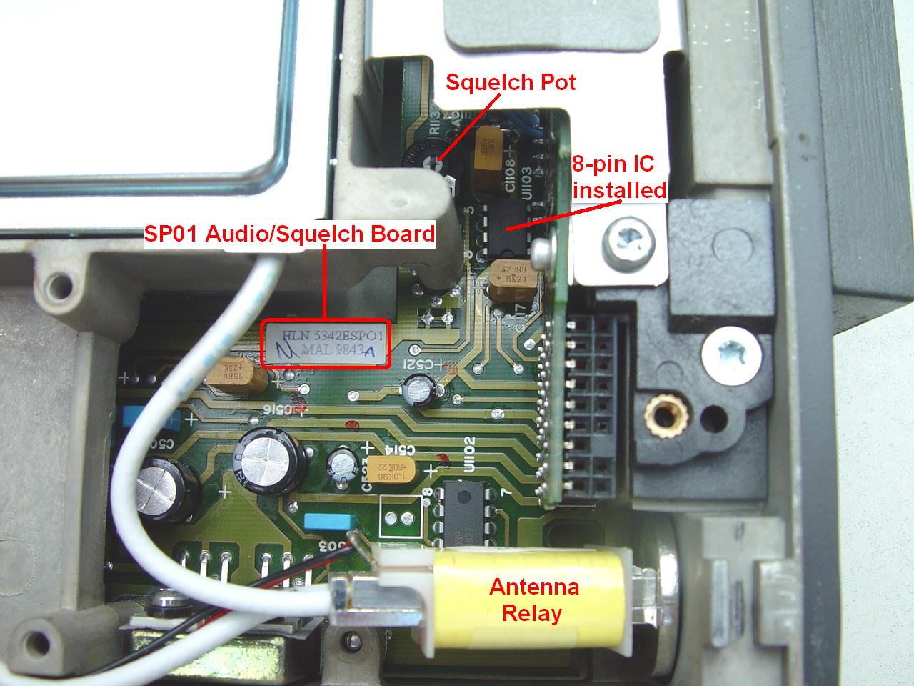
The control cable carries the signal to the radio chassis where it goes through the interconnect board and makes its way to the audio/squelch board. Rotating the remote squelch pot changes a DC voltage to a voltage-controlled amplifier in the squelch circuit, and the changing gain adjusts the squelch threshold. Some radios may contain this newer board that's manufactured without the external squelch components. Here's a photo of part of the newer audio/squelch board with some key components indicated.
I traced the signal through from the squelch pot to the audio/squelch board. The table below notes path taken and shows the signal names for the standard configuration and the remote squelch version.
| Location | Conn. | Pin | Standard | Remote Squelch |
|---|---|---|---|---|
| Inside Ctrl Head | P1050 | 14 | N.C. | Squelch Pot |
| Rear of Ctrl Head | P1001 | 32 | Horn In | Remote Squelch |
| Front of Radio | J1 | 9 | Horn In | Remote Squelch |
| Audio/Logic Board | J21 | 12 | Keyway | Remote Squelch |
Inside the control head, there's a 6.8k resistor in parallel with the 10k squelch pot. One side goes to ground; the other side goes through a 3.9k resistor before leaving the control head. The resistance to ground with the pot fully CCW is approximately 8k and there is about 2.6VDC present across the pot. The resistance decreases to approximately 4k and the voltage drops to 1.9VDC with the pot fully CW.
Squelch threshold or the lower limit is approximately 0.1uV or 2-4dB SINAD. Tight squelch or the upper limit is approximately 0.3uV or 20dB SINAD. One low-band radio that came across my bench would crack open the squelch at 0.05uV, even after being converted to 50-54 MHz operation.
You can use an advanced control head with remote squelch on a radio that was not configured for remote squelch. The reverse is probably true but I have not been tested this as I don't have an advanced control head without the squelch pot.
Acknowledgements and Credits:
All photos were taken by the authors.
Some information came from a VHF-L/VHF-H/UHF M400 Service Manual, 6880901Z56, as well as a VHF-L MaraTrac Instruction Manual, 6880102W95. RSS info came from the User's Guide, 6880102W24.
Eric WB6FLY provided the list of manuals and documentation.
Chris W1HVN supplied the low-band radio, which was subsequently converted to operate in the 46-54 MHz range.
Mike WA6ILQ provided additional historical information for this article.
Bruce KC7GR provided information about hex-editing the programming software.
MaraTrac, MaxTrac, Radius, M400, Spectra, and all the other model names and numbers mentioned in this article, as well as terms like RSS, MPL, PL, and DPL, are trademarks of Motorola, Inc.
Contact Information:
Bob can be contacted at: his-callsign [ at ] comcast [ dot ] net.
Back to the top of the page
Up one level (MaraTrac index)
Back to Home
This page originally posted on Monday 07-Jan-2008
Article text, photos, artistic layout, and hand-coded HTML © Copyright 2008 by Robert W. Meister WA1MIK.
This web page, this web site, the information presented in and on its pages and in these modifications and conversions is © Copyrighted 1995 and (date of last update) by Kevin Custer W3KKC and multiple originating authors. All Rights Reserved, including that of paper and web publication elsewhere.