MaraTrac index
Motorola index
Back to Home
MaxTrac or MaraTrac
Low-band Extender Circuit
By Robert W. Meister WA1MIK

|
MaxTrac index MaraTrac index Motorola index Back to Home |
Permanently Disabling the MaxTrac or MaraTrac Low-band Extender Circuit By Robert W. Meister WA1MIK |
|
Background:
MaraTrac and MaxTrac mobile radios use the same RF board for the receiver. Low-band models have a built-in noise blanker or "Extender" as Motorola calls it. This is a secondary receiver with an AM detector that picks up impulse noise, converts those spikes to narrow pulses, delays them a bitand uses those pulses to disable the signal path in the Intermediate Frequency (IF) circuit for a very brief time. This prevents the noise impulse from passing through the receiver and it makes the signal sound a lot better. This type of noise blanker is most effective in a mobile environment where there will be noise from other vehicles.
In the older (1970s vintage) radios, the extender had a separate front end that was tuned a few MHz away from the primary received frequency, but it performed the same blanking as the MaxTrac and MaraTrac.
When one of these radios is used as a base station or repeater receiver and there is a moderate to high ambient noise level, the noise blanker will end up working 100% of the time. This will make the receiver very insensitive as the extender circuit does its best to blank the receiver. It ends up disabling the receiver for all intents and purposes.
You can temporarily disable the extender operation by holding the MON button on the radio's control head for 3-4 seconds until the radio makes three beeps. You can re-enable the extender by repeating this operation or by cycling power to the radio. The extender circuit is activated by default and can't be changed through the programming software.
Permanently Disabling the Extender Circuit:
If you want to use one of these radios as a base station or repeater receiver, you'll want to permanently disable the extender circuit. It's actually quite easy and it can be done on the logic board, which is underneath the radios. You'll have to remove the bottom plate on a MaraTrac or the bottom cover on a MaxTrac using T10 and T15 Torx drivers.
Locate the 14-pin connector labeled "P6" on the logic board. These pins go through the chassis to the RF board on the other side of the radio. Pins 1 and 14 are marked in this photo of a MaxTrac logic board. Click on it for a larger view.
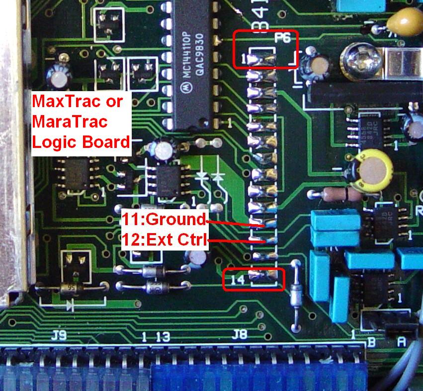
On this logic board, pin 11 has a fairly large ground foil attached to it (not all boards do). The pin next to it towards the front of the radio is pin 12. All you have to do is short these two pins together, grounding pin 12. You can heat them and add a blob of solder or bridge them with a short piece of bare wire. That's it. Button the radio back up and restore it to normal operation.
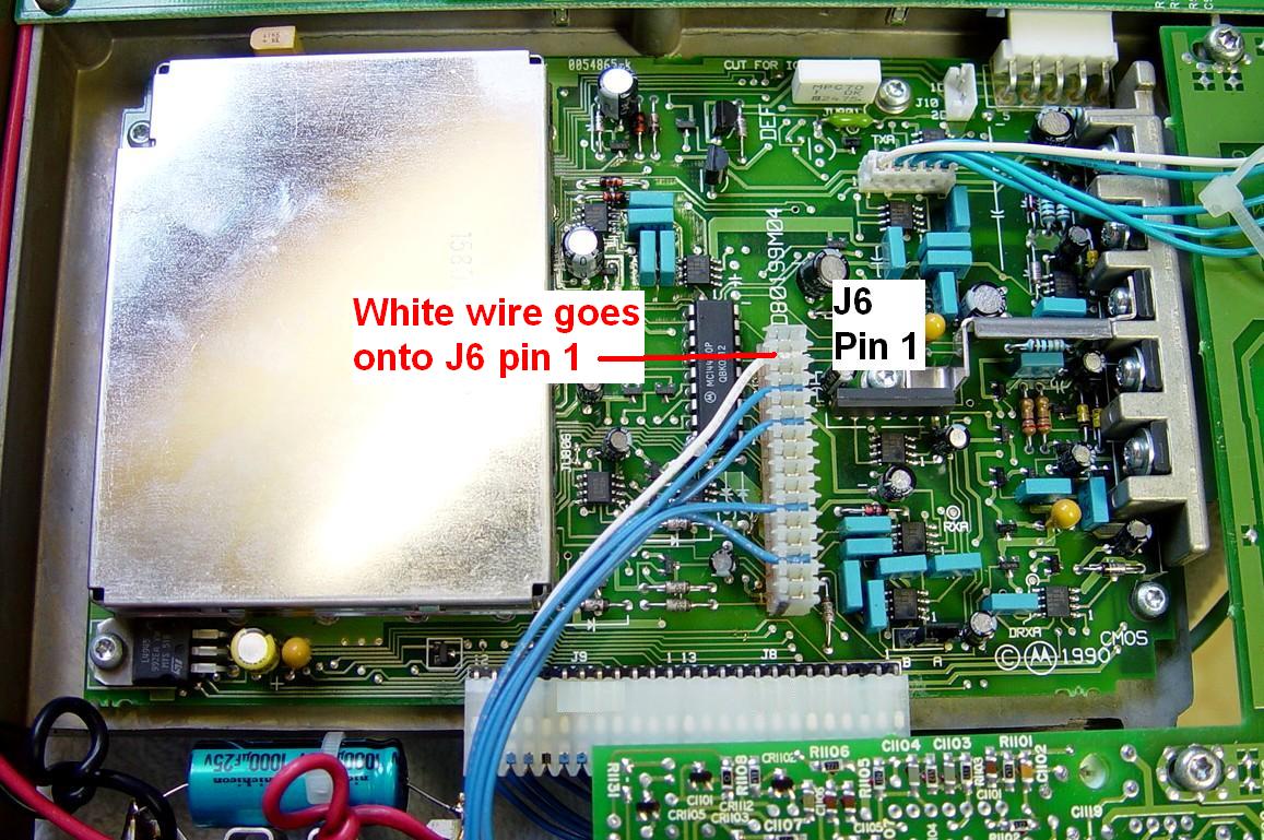
The MaraTrac radio has a 16-pin connector that plugs onto the longer pins of P6. You need to unplug this connector to access the pins beneath it. After you modify the radio, when you reinstall the connector, make sure the white wire goes onto J6 pin 1. There will be one unused contact at each end of the white connector overhanging P6. See the photo below. Click on it for a larger view.
Technical Details:
For those of you interested in what you're actually doing, here's the circuitry that you're working with on the RF Board. The extender control section of the schematic is shown below. Click on the image for a larger view.
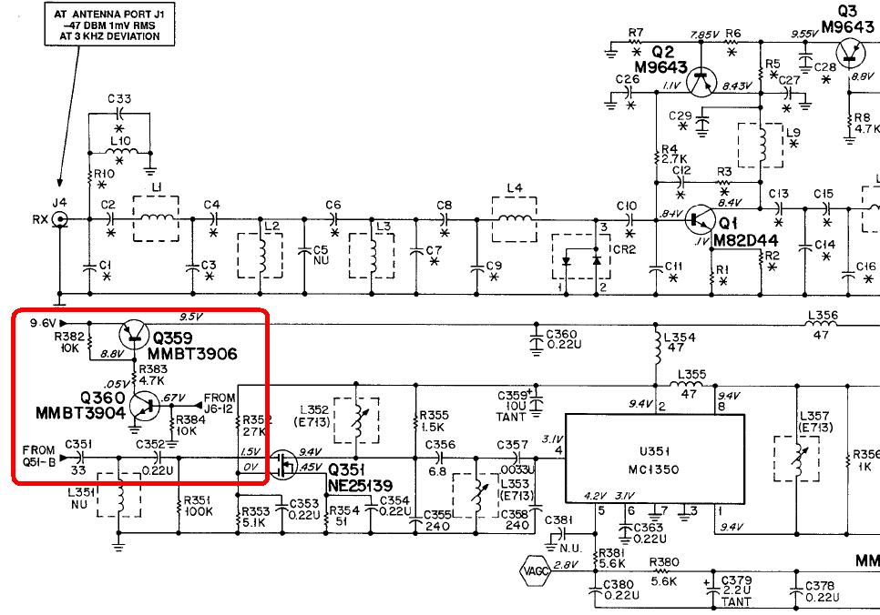
The base of Q360 is labeled "From J6-12" because the RF Board has a jack (J6) while the logic board has a plug (P6). It's the same connector; they just gave each end its own name. It's easier to add a jumper to the logic board's P6 than it is to add one to the RF board's J6. Pin 12 is pulled high through a 10k resistor by the microprocessor to enable the extender circuit, but the voltage on this pin will only reach about 0.7V because Q360 is directly connected to it. This turns on Q360, which turns on Q359, which supplies +9.6V to the extender circuitry.
When you disable the extender, either through the control head or by grounding J6 (or P6) pin 12, you prevent Q359 from turning on and supplying power to the extender circuit. Simple.
Acknowledgements and Credits:
The schematic snippet came from the MaxTrac Detailed Service Manual. The MaraTrac RF board is identical and the logic board signals on P6/J6 are the same.
All photos were taken by the author.
Contact Information:
The author can be contacted at: his-callsign [ at ] comcast [ dot ] net.
Back to the top of the page
Up one level (MaxTrac index)
Up one level (MaraTrac index)
Up two levels (Motorola index)
Back to Home
This page created on Thursday 05-Feb-2015.
Article text, artistic layout, and hand-coded HTML © Copyright 2011 by Robert W. Meister WA1MIK.
This web page, this web site, the information presented in and on its pages and in these modifications and conversions is © Copyrighted 1995 and (date of last update) by Kevin Custer W3KKC and multiple originating authors. All Rights Reserved, including that of paper and web publication elsewhere.