Motorola index
Back to Home
MaxTrac to 46-54 MHz
By Robert W. Meister WA1MIK

|
MaxTrac index Motorola index Back to Home |
Converting a 42-50 MHz MaxTrac to 46-54 MHz By Robert W. Meister WA1MIK |
|
I obtained two identical Motorola MaxTrac mobile radios: model D51MJA77A3_K. These are 60 watt, 42-50 MHz (range-3), 6-channel radios with 16-pin accessory jacks and no scan. My goal is to have them operate just as well in the 46-54 MHz range with more than six channels, and with the ability to scan.
You can click on almost all of the photos or images in this article for a larger view.
Several items or goals need to be addressed to get the radio to perform as desired. The following phases or steps will be covered in this article:
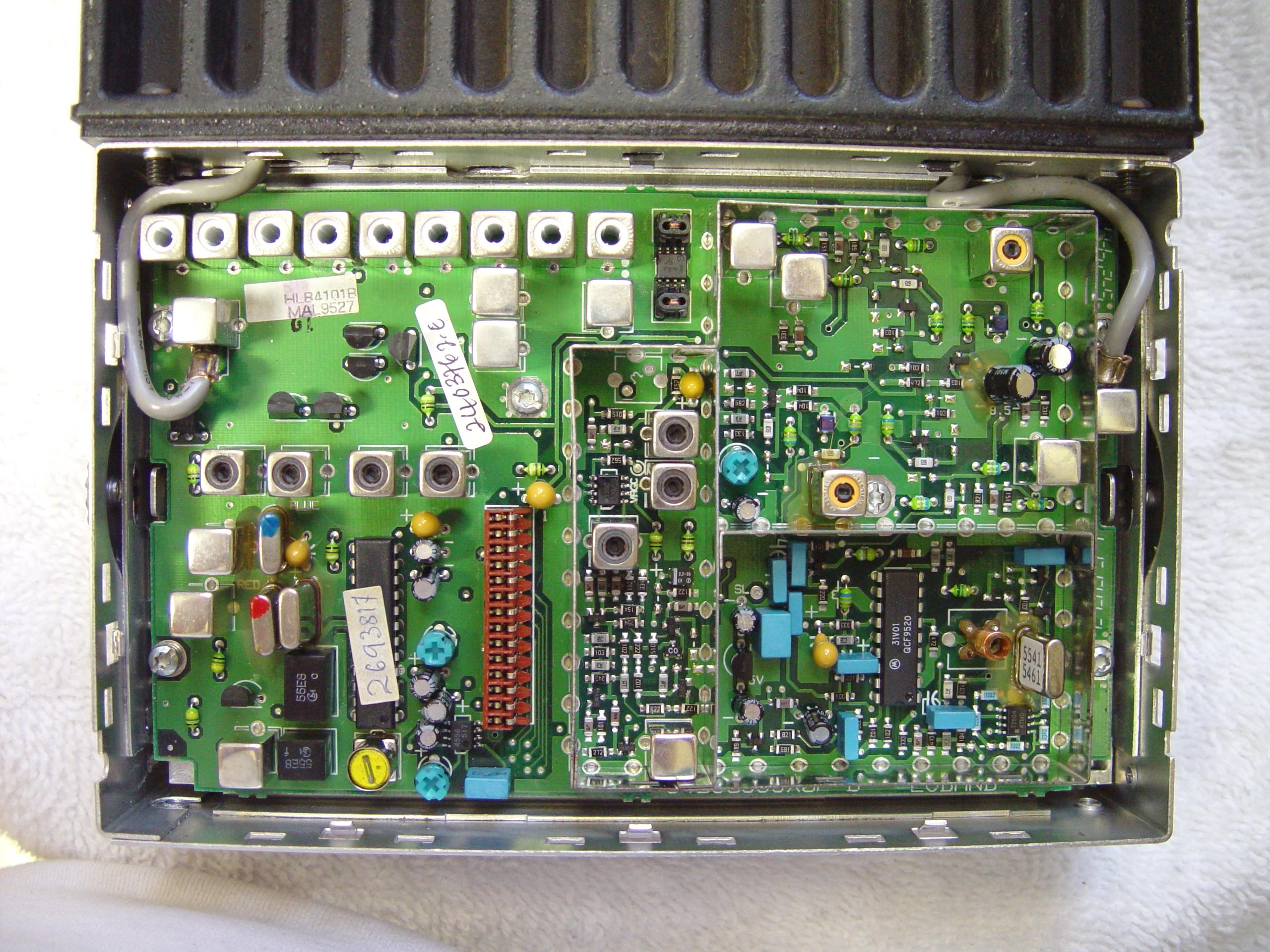
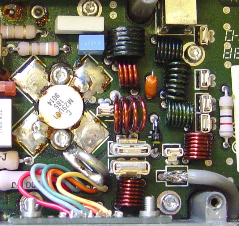
I'm extending my testing up to 56 MHz to make sure the unit is stable at 54 MHz, while sacrificing some performance below 46 MHz. The original radio was designed to span an 8 MHz range, and expanding that would require significantly more effort. All of the work takes place on the RF board and power amplifier. For reference, here's a photo of the original RF board with its main and VCO shields removed:
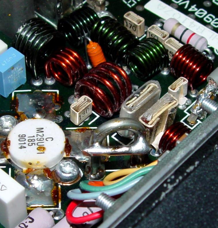
And here's the original power amplifier (PA). The cover was removed for this photo. Notice the silver-coated hairpin coil (between the green and orange wires at the top of the photo) and how tight the enameled wire coils are:
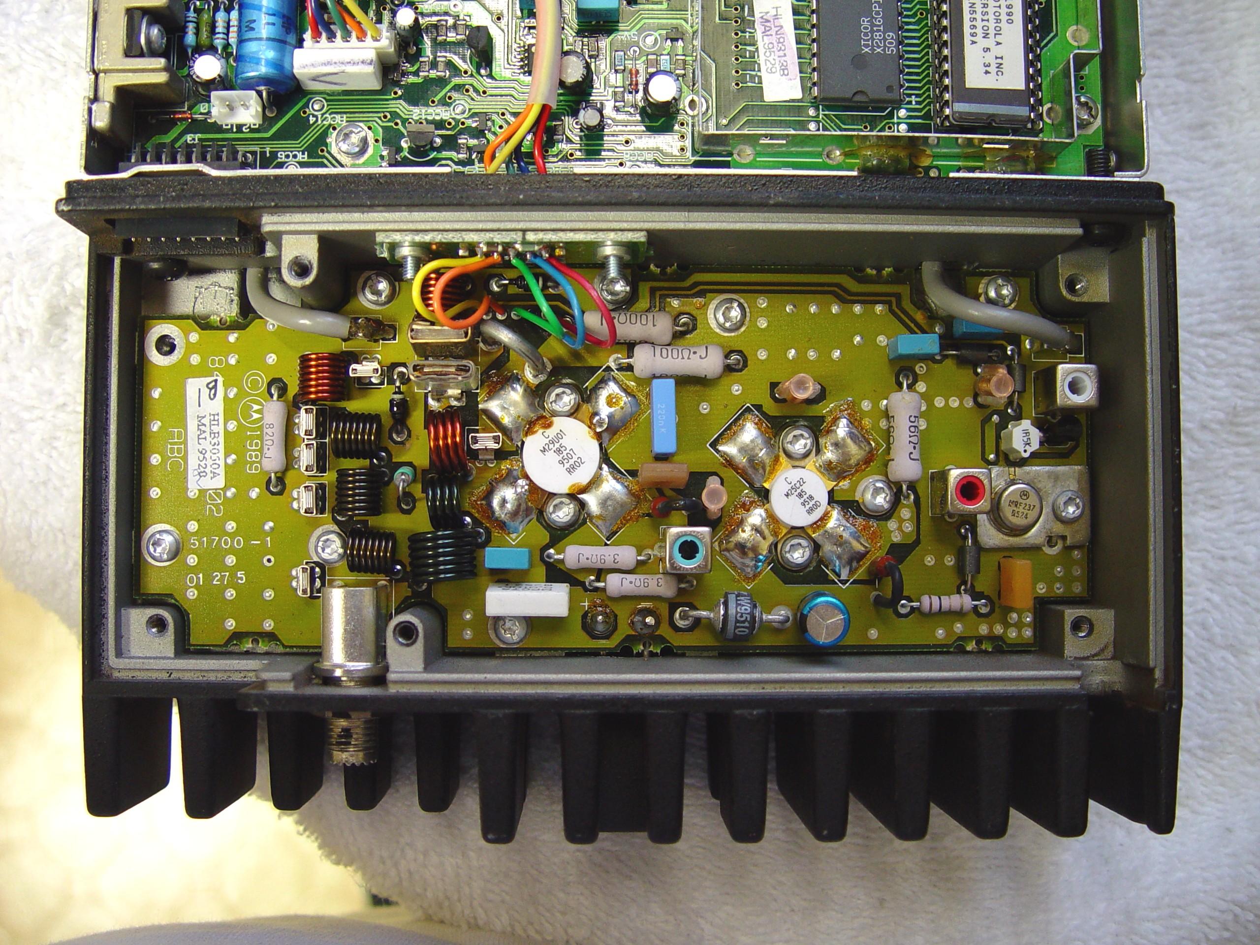
I may refer back to these from time to time.
Other than removing the plastic covers, shields on the RF board, and the metal cover over the PA, nothing else was taken apart.
Preliminary Testing:
I put both radios on the bench and programmed them to 45.3 MHz. I verified that they were on frequency (within 100 Hz), made 60 watts of power at 11 amps, and were meeting sensitivity specs (-116dBm for no crackles: about 20dB quieting). They opened squelch at -121dBm. I considered these to be acceptable and normal readings for these radios. While they were still on the bench, I ran through the board replacement procedure documented elsewhere in other articles in this section of the web site, and wrote down every setting without making any changes; this will make initialization go a lot faster later. I also saved the original code plug; better to have it and not need it than to need it and not have it.
Since I had two radios, I was able to go back and measure the transmitter spectrum of the unmodified one, after I finished fully modifying the other radio. Here's the output of the stock radio set for 60 watts, which was still programmed to 45.3 MHz, when fed through a 30dB attenuator. The second harmonic is about 58dB lower than the carrier signal, there is no 3rd harmonic, and the 4th harmonic is about 65dB below the carrier signal:
Hindsight is wonderful, especially when writing an article. This may prove to be useful later. Here are the 16 original tuning values for the power amplifier. These alignment points cover 42.000-50.025 MHz in increments of 0.535 MHz. The radio is uncontrolled and can choose any output value for frequencies outside this range.
| Point | W | 1 | 2 | 3 | 4 | 5 | 6 | 7 | 8 | 9 | 10 | 11 | 12 | 13 | 14 | 15 | 16 |
|---|---|---|---|---|---|---|---|---|---|---|---|---|---|---|---|---|---|
| Original | 60 | 88 | 84 | 81 | 77 | 78 | 78 | 79 | 83 | 86 | 90 | 93 | 97 | 100 | 102 | 104 | 106 |
I set one radio aside and began working on the other one. I programmed it with six frequencies: 42, 46, 50, 52, 54, and 56 MHz (using the SHIFT-num entry method for frequencies above 50 MHz), and measured the synthesizer's Steering Line voltage at the SL test point on the RF board, in both transmit and receive. The photo below identifies the SL test point and the two VCO coils:
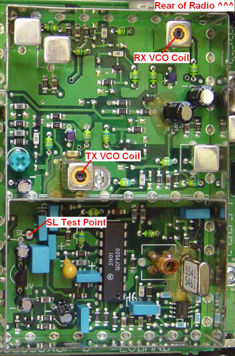
I also checked receive sensitivity and measured the transmitter's output power and DC input current, and calculated the efficiency. The receiver required -121dBm to open squelch at 46 MHz. The results are shown in the table below:
| Freq MHz | SL VDC | RX dBm |
TX | |||
|---|---|---|---|---|---|---|
| RX | TX | Watts | ADC | Eff | ||
| 42 | 2.01 | 2.17 | -116 | 60 | 11 | 39 |
| 46 | 4.50 | 4.38 | -116 | 60 | 11 | 39 |
| 50 | 7.28 | 7.31 | -116 | 60 | 12 | 36 |
| 52 | 8.62 | 8.93 | NO | NO | NO | --- |
| 54 | 8.96 | 8.95 | NO | NO | NO | --- |
| 56 | 8.97 | 8.96 | NO | NO | NO | --- |
The radio normally will not receive or transmit if the SL voltage is below about 1.8V or higher than about 7.8V, so it was basically unresponsive outside of the 42-50 MHz range.
Phase 1:
When I first got the radios, I didn't do this step right away, because I wanted to make sure they would work in the 50-54 MHz range before going further. However, it makes sense to blank and initialize the radio first, while it still covers the 42-50 MHz range. This lets you align the power amplifier over the entire range and set the output power on the test frequency, which is near 45 MHz.
Luckily, both radios already had V5.34 firmware, which supports 32 channels, scanning, and all the other neat features available in 16-pin logic boards. All I had to do was blank the radio (extended code plug) and reinitialize it to the appropriate model as detailed below. There are other articles on the web that take you through this process. Here are the details of the choices I made. Note that these are for a 16-pin logic board; you may need different choices for 5-pin logic boards. Not all 5-pin logic boards will support more than 6 channels or give you the same features as a 16-pin logic board
| Field | Value |
|---|---|
| Product Line | Max High Sig |
| Radio Series | MaxTrac 300 |
| Frequency Range | 42.0 - 50.0 MHz |
| Model Number | D51MJA9DA5_K |
| Panel Number | 001 |
| Serial Number | Same as original |
This gave me the following features: 32 Modes, 60 watts, TPL/DPL, Scan, Signaling, and Accessories.
I fully aligned the power amplifier and set the transmitter output power to 50 watts (it was 60 watts originally). This gives me a margin of safety when I start playing with the PA. It also keeps the input DC current down low enough that my Astron 12 amp bench power supply won't go into current limiting. I used the saved settings for everything else. This process takes the better part of 15-30 minutes, depending on how much effort you put into it. Here are the PA tuning values for my radio after alignment; yours will be different (slightly lower in California).
| Point | W | 1 | 2 | 3 | 4 | 5 | 6 | 7 | 8 | 9 | 10 | 11 | 12 | 13 | 14 | 15 | 16 |
|---|---|---|---|---|---|---|---|---|---|---|---|---|---|---|---|---|---|
| Original | 60 | 88 | 84 | 81 | 77 | 78 | 78 | 79 | 83 | 86 | 90 | 93 | 97 | 100 | 102 | 104 | 106 |
| Aligned | 50 | 78 | 74 | 70 | 68 | 65 | 68 | 71 | 74 | 77 | 80 | 83 | 86 | 89 | 91 | 93 | 94 |
The higher values at the upper tuning points are causing the input current to be higher at 50 MHz.
After initializing the radio, all of the tuning points will have the same value. It makes sense to leave them there and adjust the power to 40-50 watts using the alignment screen.
Phase 2:
I put the probe of my digital multi-meter on the SL test point and adjusted the receive VCO coil, then the transmit VCO coil, for 7.00V at 54 MHz, using a small straight-blade alignment tool. Be careful; those ferrite cores can easily break. I turned each coil counter-clockwise (out) about 4 turns, and measured the radio again. Remember that I set the output power to 50 watts during the previous step:
| Freq MHz | SL VDC | RX dBm |
TX [see notes] | |||
|---|---|---|---|---|---|---|
| RX | TX | Watts | ADC | Eff | ||
| 42 | 0.56 | 0.98 | -116 | 50 | 9.5 | 38 |
| 46 | 1.90 | 2.28 | -116 | 50 | 9.5 | 38 |
| 50 | 4.31 | 4.33 | -116 | 50 | 11.0 | 32 |
| 52 | 5.65 | 5.61 | -111 | 25 | 7.5 | 24 |
| 54 | 7.00 | 7.01 | -101 | 30 | 8.0 | 27 |
| 56 | 8.35 | 8.56 | -88 | 20 | 7.5 | 19 |
Other than the output power and sensitivity, at least the radio seems willing to operate in the 50-54 MHz range. The photo below shows the two VCO coils with their adjusting cores sticking out of the coil forms 3-4 turns. You don't have to go quite as far as I did; you can adjust them for 7.5V at 54 MHz; I just wanted to get a little bit more out of the radio.

I actually started my conversion with this step, to see how bad the receiver and transmitter would perform in the amateur band. After finding out, and knowing that I could easily adjust the VCOs, I realized I would have to un-do this when initializing the radio. Luckily it's very easy to return the two VCO cores back to the top of the coil forms, which is where they originally were on this radio. This step takes about one minute.
If you'll be using one of these radios as part of a repeater, you can adjust the appropriate VCO for a steering line voltage of anywhere between 3 and 6 volts DC at the frequency of interest.
You should check and possibly adjust the deviation alignment settings of the radio after you adjust the transmit VCO coil.
Phase 3:
There was already some information on the web about the modifications needed for the power amplifier. Unfortunately, there were no photos, schematics, or circuit board layouts provided, so it was difficult to interpret the intent of the other authors. I decided that this article should fill in the gaps and provide everything you need to do the job right, since not everyone has the MaxTrac Detailed Service Manual. Existing instructions just said the following:
By the way, this coil is officially identified as L2143. One person's idea of "Flow solder on the top and sides..." means different things to different people. My first attempt used a 100w/140w Weller soldering gun to heat the coil so solder would melt and stick to it. I ended up melting the solder holding the coil to the circuit board, and it almost fell out; this was not what I wanted to do. Any solder I added just flowed elsewhere.
I did discover, on the second radio, that the five colored wires, which were placed close to this loading coil, DO have an effect on the radio. I had moved them out of the way before adding solder; you can see them resting against the loading coil if you look at the original PA photo. While I couldn't see anything on the meters, the radio did act differently with the wires pushed back away from the loading coil.
My second attempt used a 40w soldering iron, and I tried putting blobs of solder all over the coil. It looked ugly, but it made a small improvement in the 50-54 MHz range while lowering the output power in the 42-50 MHz range. Having never seen a radio modified in this manner, I had no idea exactly what was needed.
I ended up removing all the solder I had added, by turning the radio upside down and applying heat to the coil. The solder melted, coagulated into a couple of big blobs, and gravity did the rest. Just make sure the area where the solder falls is immune to hot solder splashing (i.e. avoid doing this over your lap while wearing shorts). With only a very thin coat of solder remaining I still didn't experience any noticeable change, so, with the help of Dave N1OFJ, on to Plan B.
Additional text (with grammatical errors left intact) suggested spreading various PA coils, but without a layout or other identifying information, this can be rather hard to do:
I used a small plastic putty knife to spread the coils. They're coated with enamel, and sometimes the windings stick together. A small piece of wood can be sharpened or sanded to become wedge-shaped and this will let you play with the coils while the radio is powered up.
Here's a photo of the final stage of the PA:
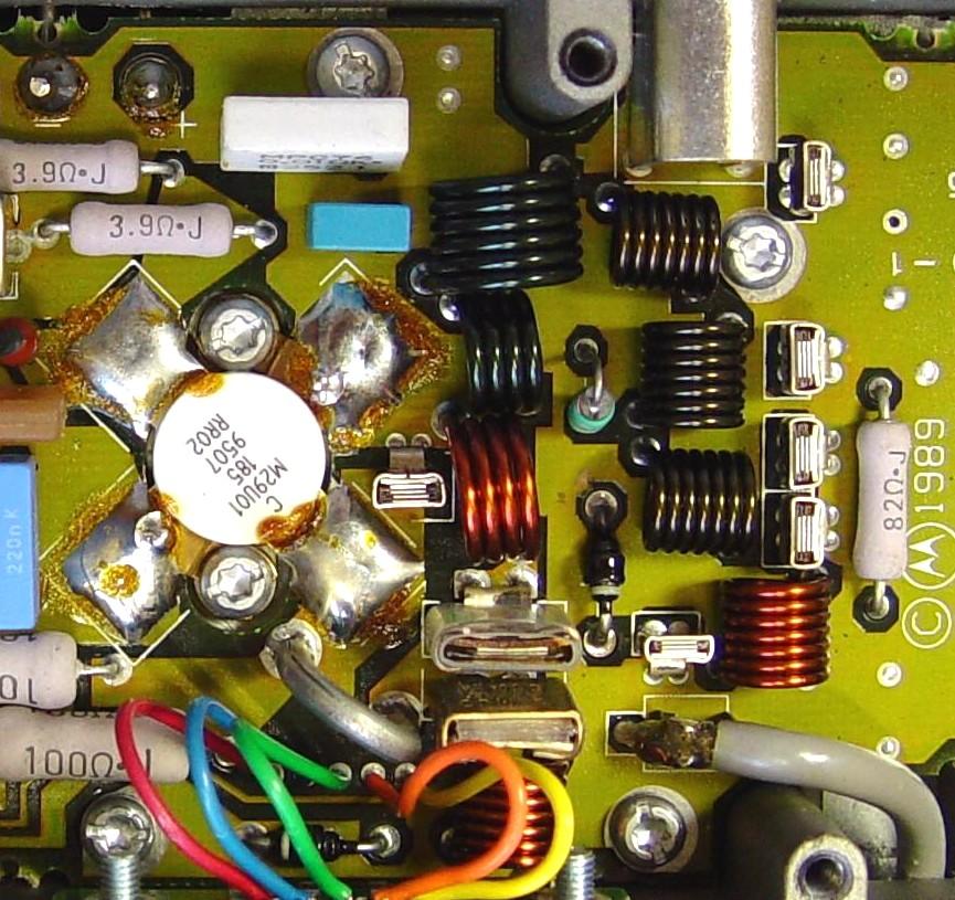
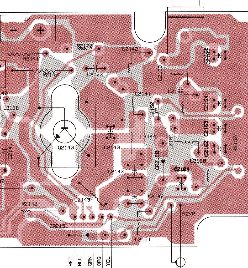
Here's the circuit board X-ray view of that same area of the PA:
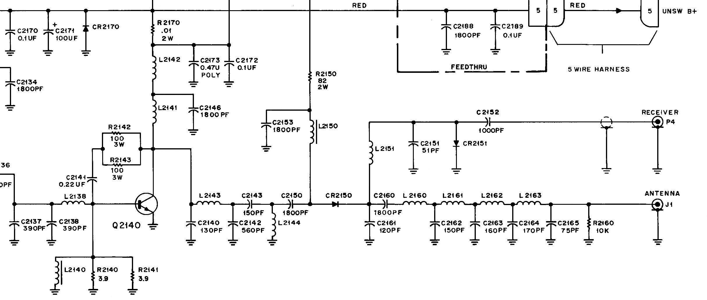
And to be complete, here's a portion of the PA schematic:
After spreading several of the coils, I was able to get almost 50 watts at 52 MHz, but the radio was going crazy at 50 MHz, putting out nearly 100 watts and drawing almost 15 amps. In fact, my power supply was going into current limiting at that point. 54 MHz still was low and at 56 MHz the transmitter would peak then cut back.
When I realigned the PA during the initialization process, the PA tuning values were rather high at the upper portion of the band. I went back into RSS and set all 16 tuning points to 67, which was what the power level was set to in the alignment screen. This made quite a difference, and I was able to spread the various coils out to make the output power fairly even across the operating band. There are still odd things happening at 42 and 56 MHz, but between 46 and 54 MHz it seems to be quite happy. Here are the PA tuning values:
| Point | W | 1 | 2 | 3 | 4 | 5 | 6 | 7 | 8 | 9 | 10 | 11 | 12 | 13 | 14 | 15 | 16 |
|---|---|---|---|---|---|---|---|---|---|---|---|---|---|---|---|---|---|
| Original | 60 | 88 | 84 | 81 | 77 | 78 | 78 | 79 | 83 | 86 | 90 | 93 | 97 | 100 | 102 | 104 | 106 |
| Aligned | 50 | 78 | 74 | 70 | 68 | 65 | 68 | 71 | 74 | 77 | 80 | 83 | 86 | 89 | 91 | 93 | 94 |
| Final | 50 | 67 | 67 | 67 | 67 | 67 | 67 | 67 | 67 | 67 | 67 | 67 | 67 | 67 | 67 | 67 | 67 |
The 16 alignment points cover the 42-50 MHz operating range of the low-band radio. Since we'll be operating the radio way out of range, the resulting RF power level is behaving just like any other MaxTrac operating out of range. You may have to do the manual power adjustment modification (described elsewhere in this section of the web site) to get stable power.
After setting the PA tuning values to the same number, I found the transmitter output was a lot more consistent, nearly 50 watts from 46 to 54 MHz. Dave N1OFJ tuned two other radios after helping me with this one, and he also set the PA tuning values to the same number. This step seems to be critical. The actual number used (60-70) can be changed later through the transmitter output power setting in the RSS Alignment screen.
| Freq MHz | TX Before | TX After | ||||
|---|---|---|---|---|---|---|
| Watts | ADC | Eff | Watts | ADC | Eff | |
| 42 | 50 | 9.5 | 38 | 20 | 7.5 | 19 |
| 46 | 50 | 9.5 | 38 | 50 | 8.5 | 42 |
| 50 | 50 | 11.0 | 32 | 55 | 8.0 | 49 |
| 52 | 25 | 7.5 | 24 | 45 | 7.5 | 43 |
| 54 | 30 | 8.0 | 27 | 55 | 8.5 | 46 |
| 56 | 20 | 7.5 | 19 | 15 | 4.5 | 24 |
Your radio will be different; this is definitely a trial-and-error procedure, and it could take anywhere from a few minutes to half an hour until you're satisfied with the output power. This is the one part of the project that can't be described as "do this and you're done." The table below documents how much, if at all, the various coils were played with.
| Coil # | Color | How It Was Modified |
|---|---|---|
| L2141 | Green | Spread wide |
| L2142 | Green | Leave alone |
| L2143 | Silver | Add a slight layer of solder |
| L2144 | Copper | Spread wide |
| L2151 | Copper | Leave alone |
| L2160 | Copper | Leave alone |
| L2161 | Green | Spread wide |
| L2162 | Green | Spread wide |
| L2163 | Green | Leave alone |
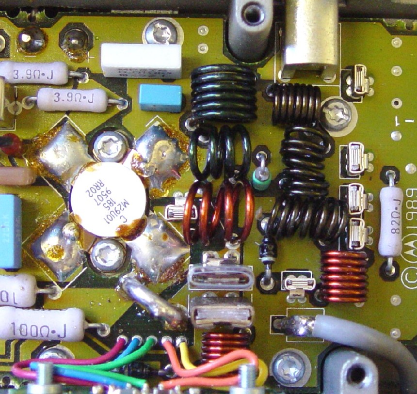
Make sure the coils don't hit adjacent components when you spread the turns out. The photo below shows the final product:
Just to make sure the transmitter isn't throwing out all sorts of spurs and harmonics, I measured the output with a spectrum analyzer, paying particular attention to the range of 1 MHz to 200 MHz. On 42 MHz I found two good-sized spurs a few MHz away from the carrier, but on all other transmitter frequencies the 2nd harmonic was the only visible spur, and that was down about 60dB; the spec is -61dB. There were no other harmonics visible. Here's the spectrum analyzer output of the modified radio making 45 watts at 52 MHz, when fed through a 30dB coaxial attenuator:
The second radio went a lot faster. Everything went as planned and just like the first radio, but I spent a bit more time on the PA and never added any solder to the U-shaped coil. I didn't think it needed it; perhaps it lowers the DC current drain, thus raising the efficiency. This radio seemed to be stable on all of my test frequencies. I set it to about 50 watts at the RSS test frequency with the PA cover off. Here are the results on this radio when all closed up and ready to ship (I didn't bother recording the original values):
| Freq MHz | TX After | ||
|---|---|---|---|
| Watts | ADC | Eff | |
| 42 | 55 | 10.5 | 37 |
| 46 | 52 | 10.5 | 35 |
| 50 | 50 | 10.0 | 36 |
| 52 | 55 | 10.5 | 37 |
| 54 | 60 | 10.5 | 41 |
| 56 | 45 | 9.5 | 34 |
This radio isn't quite as efficient as the first one, but the output power is more stable and uniform. I will be playing with the first one to get it better than it currently is and will update this article if any noticeable improvement is made.
After programming 18 repeater frequencies into the radio, output power measured about 57 watts on all channels at just over 10 amps.
I subsequently went back and played with the first radio in an effort to balance the output power better. I played with the coils while checking the power at the test frequencies, and adjusted the coils so the power was lower but the same value. It ended up around 45 watts on 46-54 MHz. I then went back into the alignment screen in RSS and pushed the output power up to 60 watts. Everything seemed to be working fine at about 10 amps. The tuning changed ever so slightly when I put the cover back on the PA.
Phase 4:
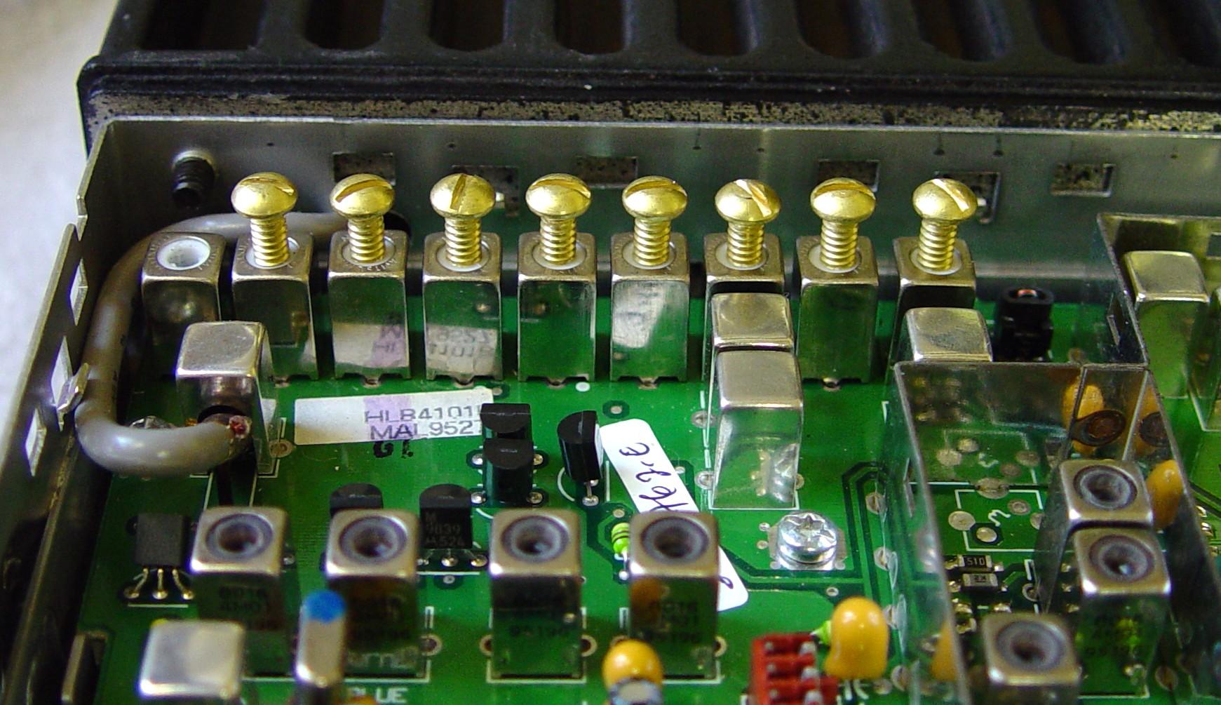
I purchased some #6-32 1/2 inch long round-head solid-brass machine screws from my local home improvement store. You can also use flat-head screws. They cost about $1 for a package of six screws, and you'll need eight screws to do one radio. I set the signal generator for a usable signal on 52 MHz and carefully threaded screws (make sure they go in perfectly straight) one at a time into the receiver's front-end coils, listening for less noise out of the speaker. I found that inserting a screw in the left-most coil (closest to the antenna input) actually made the signal worse, but adding one to each of the other eight coils did improve the signal quite a bit. To make it easier to see the tuning effect, I connected an AC voltmeter to the speaker output and adjusted the screws for lowest indication (least noise) on the meter. Here's a photo of the radio with the full-length screws installed:
Here are the results before and after this process:
| Freq MHz | RX dBm | |
|---|---|---|
| Before | After | |
| 42 | -116 | -92 |
| 46 | -116 | -113 |
| 50 | -116 | -116 |
| 52 | -111 | -116 |
| 54 | -101 | -116 |
| 56 | -88 | -115 |
After adjusting the squelch pot on the RF board, the radio now opens squelch with a signal on 52 MHz at -128dBm.
There's at least 1/4 of an inch of unused thread visible, and the screws stick out too far to put the shield and covers back on the radio, so I cut 3/16 inch off the screws. The tuning of some screws was rather broad and provided little improvement, while others were very sharp and noticeable.
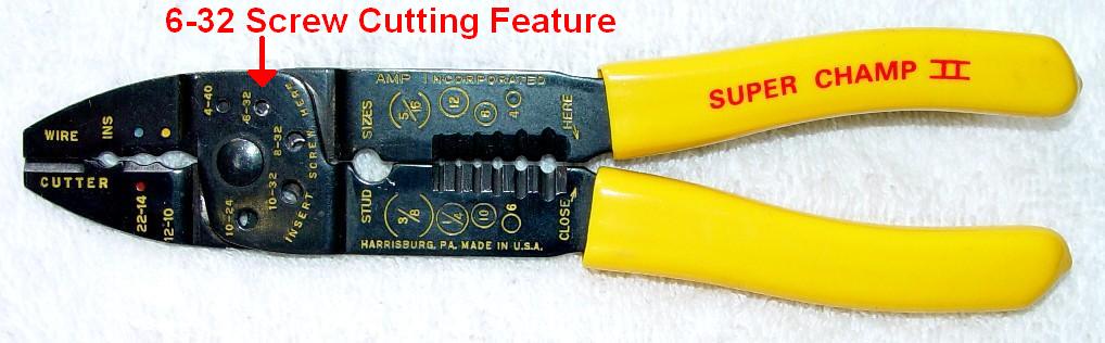
I used a multi-purpose crimping/stripping tool that also had the ability to cut common machine screws. See the photo below. I threaded one screw into the closed tool until it bottomed out, then opened the tool, aligned the holes, and turned the screw six more turns. At 32 threads per inch, this shortened the screw by 6/32 or 3/16 of an inch. Close the tool and the screw will be cut cleanly.
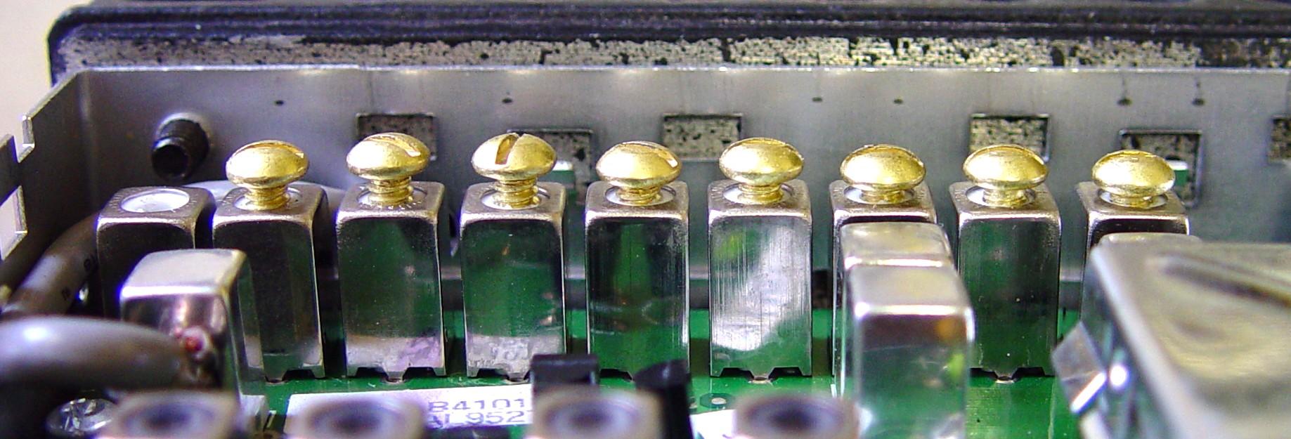
Thread one original screw into each coil form 1/4 inch, then remove it and insert a cut screw into the coil form. It will go in a lot easier, since the cut screw doesn't have a chamfered end after becoming shorter. Put the short screws in all the way until they just touch the top of the coil form, then back them out two turns; this will be just about the perfect spot for 52-54 MHz. This step takes five minutes to do. Here's a view showing the shorter screws in their final position:
You can opt to tune the receiver at 50 MHz and get it to cover the 46-54 MHz range with decent sensitivity. You won't have to thread the screws in as far, and you can cut them shorter afterwards. I don't plan to use the radio below 50 MHz.
If you can find #6-32 screws that are 5/16 or 3/8 inch long, you probably won't have to cut them shorter. 1/4 inch #6-32 setscrews will also work if you insert them all the way flush with the top of the coil form. Another alternative is to use #6-32 stainless-steel setscrews that are 1/4 inch long. Insert them so they are flush with the top of the coil form. I found that these didn't give me quite the same increase in sensitivity as the brass screws.
The industrial supplier McMaster-Carr sells #6-32 brass (hex-head) setscrews that are 1/4 inch long. A box of 50 costs about $5US ($10US delivered) and is enough to do six radios. Their part number is 92991A144. No cutting is needed; just thread them in with a 1/16-inch Allen (hex) wrench until they're flush with the top of the coils. Thanks to John W1GPO for buying some and confirming that they work extremely well. (Update in April 2019: the screws are about $6 and about $12 delivered. I had nothing else to buy from them to help amortize the shipping cost.)
After installing one of these radios in a vehicle, we discovered that the squelch setting was way too loose and was chattering all the time. I had set it on the bench to open at 0.1uV (-127dBm); that's way too low. We bumped it up to 0.141uV (-124dBm) and that was much quieter.
For people outside the United States, I've been told that M3.5x0.8 Metric hardware fits fine. You can use round head screws or hex setscrews as long as they're brass. You may have to get longer screws and cut them down to length.
You need to perform Phase 3 before you perform Phase 4, since the harmonic filter on the PA is ahead of the receiver's input coax, and you will gain a significant amount of sensitivity (3-6dB) in the ham band just by spreading those coils. If you're only going to use the receiver, you still need to spread out the harmonic filter coils on the PA.
Phase 5:
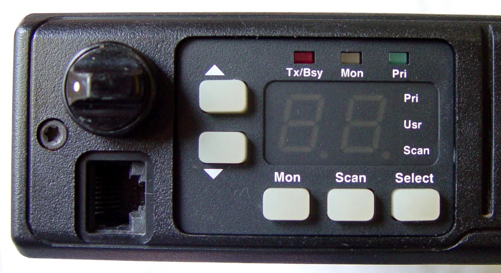
Here's the original control panel from these radios:

I removed the control head from the radio chassis, unscrewed the display board from the control head, and popped out the original non-scan escutcheon. I cleaned the control head, display board, and silicone buttons while they were out, then installed a new escutcheon, Motorola p/n 1380277L01, which is surprisingly still available for just under $5US. The two-channel escutcheons, Motorola p/n 1380276L02 were No Longer Available when I wrote this article; it seems they're back into stock as of June 2008 and sell for $3.50US. The display board was installed and the control head put back on the radio. This took another five minutes. Here's the completed control panel:
Other Items:
You should check (and adjust if necessary) the warp frequency and the deviation. It makes sense to remove the RF board and clean the pins going to the logic board, before doing anything else, as this can have an effect on the reference oscillator frequency.
One radio was found to have over 20 kHz deviation on 53.7 MHz. Turning the deviation setting to zero didn't lower it enough; we had to go through the board initialization procedure and set the Total Deviation With PL setting down quite a bit to get the radio down to 4.5 kHz deviation. As these radios weren't designed to operate out of the particular band they were built for, we have to take extra steps to tame them when operating out of band. You may have problems getting the deviation to be acceptable at 46 MHz as well as 54 MHz. I didn't care too much about anything outside of the amateur band, but others may use it for dual purpose.
Further experimentation with this high-deviation radio showed that the voltage controlling the deviation circuit was around 4V on 42-50 MHz channels, but rose to over 8V on 53 MHz channels, thereby drastically increasing the radio's deviation. This is due to the microprocessor being unable to decide what value to send to the radio to control it outside the normal 42-50 MHz range. Some radios work fine, some don't. This one was a 2-channel radio with an HLN5172A 5-pin logic board and original firmware. We eventually added a manual deviation potentiometer to better control the transmitter's deviation.
Results:
So, how did we do? The final radio does seem to meet all of my original goals:
The radio actually performs well in the 46-54 MHz range, so it would still be quite usable on some of the American Red Cross frequencies. Apparently many hams are affiliated with that organization and use their radios for dual purpose. If you need good performance down there too, tune your radio at 50 MHz instead of 52 MHz.
Just like the big red Staples button says: "That was easy!" (I couldn't resist.)

Another Radio For Comparison:
A friend had a 42-50 MHz Radius radio that had been converted to a six meter MaxTrac by someone else a while ago. He loaned it to me so I could see what was done to it and check the resulting performance.
I found a couple of the PA coils had been widened. See the photo below.
I found a large piece of wire soldered across the U-shaped coil. See the photo below.
There were brass flat-head screws, about 3/8 of an inch long, inserted into two of the nine receiver front-end coils, the 3rd and the 7th from the left.
Both VCO coil slugs were extended about two turns up from the top of the coil form.
The results of these modifications are listed in the table below. There were several frequencies in the 46-47 MHz range, as well as several six meter simplex and repeater frequencies in the 51-53 MHz range.| Freq MHz | Transmitter | RX dBm | |||
|---|---|---|---|---|---|
| Watts | ADC | Eff | Sens | Op Sq | |
| 46.000 | 40 | 11.8 | 24 | -115 | -124 |
| 52.525 | 57 | 10.2 | 40 | -112 | -121 |
| 53.850 | --- | --- | --- | -111 | -118 |
The receiver could definitely be improved by adding more brass screws to the remaining front-end coils. The transmitter could be made more efficient below 52 MHz by spending more time adjusting the coils.
Per the owner's request, I added six brass screws to the receiver front-end coils. This increased the sensitivity on 52.525 MHz to -116dBm. The radio now opens squelch at -124dBm on the amateur frequencies.
Reversing The Changes:
If for some reason you want to restore the radio to its stock condition, all of the changes and modifications can be un-done, if you saved some stuff when you started.
Yet Another Method:
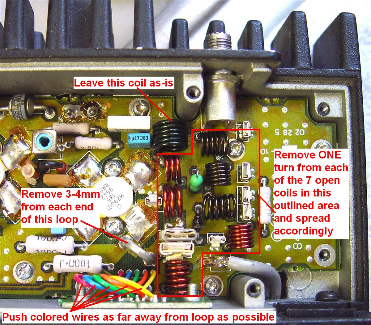
John W1GPO experimented with a more agressive and irreversible modification that involves removing one turn from seven coils and shortening the hairpin loop by 3-4mm. The following table has the details. Refer to the original photo and parts layouts above.
| Coil ID | Original Turns | Modified Turns | Notes |
|---|---|---|---|
| L2142 | 6 | 6 | Leave as-is |
| L2141 | 4 | 3 | |
| L2141 | 4 | 3 | |
| L2143 | 1 | 1 | Shorten by 3-4mm |
| L2151 | 7 | 6 | |
| L2163 | 7 | 6 | |
| L2162 | 7 | 6 | |
| L2161 | 7 | 6 | |
| L2160 | 7 | 6 |
To perform this work, you will need to remove the PA circuit board from the heatsink. This involves unsoldering the DC power connector pins, unplugging the two coax lines from the RF board, removing the connector that goes to the logic board, and removing a lot of screws. Unsolder one coil at a time, unwind one turn from one end, cut the excess off, scrape the enamel off, and solder the coil back into the board.
The hairpin loop (L2143) has two crimps in the wire, to keep it from falling through the circuit board. After removing the coil, cut each side right at the crimps, squeeze, file, or cut the crimped metal off so the part will fit through the hole, and insert it back into the board as much as it was originally, just enough to solder the top and bottom foils. If you take too much off, efficiency really drops off below 50 MHz.
Besides shortening the coils, move the five colored wires near L2151 as far away from that coil as possible, flattening them against the chassis near the connector. Some of the coils will still need to be spread out to achieve optimum efficiency. Do one coil at a time in sequence. The cover doesn't have to be installed while adjusting them. See the photo below of a converted radio with the modifications marked.
The radio modified in this fashion was quite efficient, drawing around 8 amps to produce just over 40 watts of power. The power was also very consistent across the entire six-meter band.
Test Equipment:
This is a list of the equipment I used. You don't need a spectrum analyzer, but since I have one, I used it. Any good service monitor will be more than sufficient for doing this conversion.
Acknowledgements and Credits:
Thanks go to Jim N1GTL for providing the radios and trusting me to convert them. He now has one in his vehicle and one at home, which I subsequently purchased.
Dave N1OFJ gave me guidance and assistance with tweaking the power amplifier and choosing the screws for the receiver front-end. He also gave me valuable feedback when he tuned several new radios.
Chris W1HVN loaned me his low-band Radius (now MaxTrac) mobile radio for comparison.
John W1GPO brought his modified radio to my house so we could evaluate it.
Mike WA6ILQ gave me valuable pointers and suggested additional material.
Schematic and parts layout information came from the MaxTrac Detailed Service Manual, p/n 6880102W84, No Longer Available.
MaxTrac and Radius are trademarks of Motorola, Inc.
The "Easy button" image came from the Staples office supply web site and is a registered trademark of Staples, Inc.
All photos were taken by the author.
Contact Information:
The author can be contacted at: his-callsign [ at ] comcast [ dot ] net.
Back to the top of the page
Up one level (MaxTrac index)
Up two levels (Motorola index)
Back to Home
This page originally posted on Wednesday 15-Jan-2008
Article text, artistic layout, and hand-coded HTML © Copyright 2007 by Repeater-Builder.
This web page, this web site, the information presented in and on its pages and in these modifications and conversions is © Copyrighted 1995 and (date of last update) by Kevin Custer W3KKC and multiple originating authors. All Rights Reserved, including that of paper and web publication elsewhere.