|
Maxtrac Index Motorola index Back to Home |
An addendum to my MaxTrac 800 MHz to 900 MHz Receiver Conversion Article By Robert W. Meister WA1MIK |
After writing my previous article that converted one model 800 MHz radio to receive the 902-928 MHz amateur band, I was informed of additional possibilities that would allow more radios to receive the same band and possibly transmit at the low end of the band as well. Naturally, I had to investigate these modifications and try them for myself.
Disclaimer: I would not attempt to use a converted 800 MHz transmitter in a repeater - use a 900 MHz MaxTrac because it's really meant for the task (narrow band, properly tuned, etc). Obviously any such alterations to radios are done by the owner with the undertstanding that he/she is totally responsible for the outcome and use thereof.
Background:
The 800 MHz MaxTrac radios come with one of two RF boards:
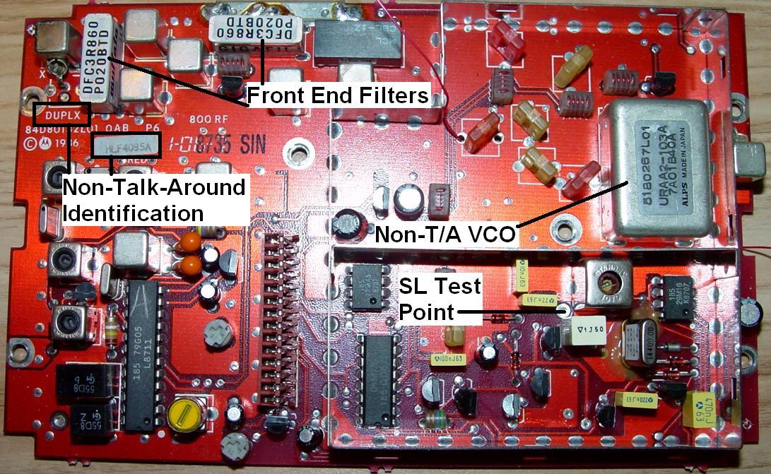
One, the HLF4095, is labeled DUPLX near the top left corner. This board receives 851-870 MHz and transmits 806-825 MHz (called "non-talk-around" or "non-T/A" in Motorola's vocabulary).
|
Click on the image for full size. |
The other, the HLF9122, is labeled SIMPLEX in a similar area. This board receives 851-870 MHz and transmits both 806-825 MHz and 851-870 MHz (called "talk-around" or "T/A" in Motorola's vocabulary, because you talk around the repeater. Hams would call it "simplex", or "direct"). The VCO has an extra pin on it (called "shift") and a logic level on that pin switches the VCO between the two frequency ranges.
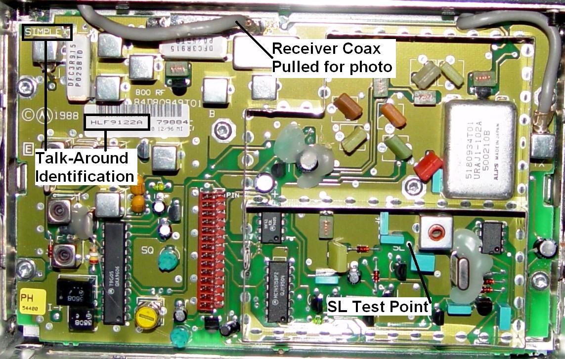 |
Click on the image for full size. |
My previous article only dealt with the talk-around board, because the talk-around part of the VCO on that model was able to go high enough to allow reception of the 902-928 MHz amateur band. The non-talk-around VCO does not. Here's why.
The basic non-talk-around VCO operates from 806-825 MHz, the same frequency as the transmitter. The receive frequencies are 45 MHz higher. The receiver's IF frequency just happens to be 45.1 MHz; I'm sure this is no coincidence. This means the VCO operates in the same range for receive as it does for transmit. When the VCO is running at 806.0 MHz, it will allow reception of a signal on 851.1 MHz, and when its running at 825.0 MHz, it will pick up a signal on 870.1 MHz. This is fine for the 800MHz commercial band repeater operation that the radio was originally designed for.
The talk-around VCO operates in either of two ranges, depending on the logic level applied to the "Shift" pin. One is the same as I've shown above: 806-825 MHz. The other range, 851-870 MHz, is selected when the VCO's shift signal (pin 1) is high. In my previous article, I forced this condition by shorting Q205 to keep the VCO's pin 1 high all the time. Since the receive frequency is 45.1 MHz higher than the VCO frequency, this lets the radio pick up signals in the 896-915 MHz range. Luckily, the VCO will go even higher in frequency, and it covers the entire 902-928 MHz band quite well. The fact that the VCO has the extra pin and this second range is why the radio can be so easily converted to receive the 900 MHz amateur band: we simply lock the synthesizer into simplex transmit mode and the receiver listens 45.1MHz higher than it thinks it is.
What I've Learned:
Recently, I became aware of a modification that would let 800 MHz radios receive AND TRANSMIT in the 900 MHz amateur band. This information came from Dan W2PUT, and he deserves all of the credit for this discovery. I've just refined it a bit and done more analysis. Basically, the VCO is modified to raise its range to allow the radio to transmit around 902 MHz and receive around 927 MHz. I had a non-talk-around MaxTrac just waiting for another use, and this seemed like a great opportunity to try it.
Finally, a real good use for these 800 MHz radios. I hear you saying "Wow, cool!"
I hate to burst your bubble, but I'll tell you the bad news now. The RF boards have tuned circuits in the transmitter buffer stages. On the non-talk-around board, these limit its operation to the expected transmit portion of the band, i.e. from 806-825 MHz. These boards will NOT produce any signal to drive the power amplifier to allow transmission in the low end of the 900 MHz amateur band, even after the VCO has been modified.
The good news is that at least you can modify a non-talk-around radio to receive the entire 900 MHz amateur band. This requires modification of the stock VCO. You still have to replace the front-end filters, obtain conventional firmware, blank the board, and initialize it. This procedure was covered in my previous article.
There's even better news. Several coils in the transmit section of the non-T/A RF board can be shortened to allow the radio to transmit in the low end of the 900 MHz band and receive the high end of the band, which was my original goal. So now your bubble can be partially re-inflated, because we really have reached that "Wow, Cool!" point.
The Possibilities:
First, you must have a working and aligned 800 MHz MaxTrac. It can be either a 15- or 35-watt version. Now is the time to adjust the power and deviation because the test frequencies used by RSS are all in the 800 MHz band and they won't do you any good once you've converted the radio to receive (and transmit) in the 900 MHz band. Emphasis: You must have a properly working and aligned radio before you go any further!
The following items must have already been done by following the procedures in my previous article:
| 800 MHz MaxTrac Conversion Possibilities | |||||
|---|---|---|---|---|---|
| Case | RF Board | RX Range | TX Range | VCO | Coils |
| 1 | T/A | 902-928 | None | OK As-Is | OK As-Is |
| 2 | T/A | 927-928 | 902-903 | Modify | OK As-Is |
| 3 | Non-T/A | 902-928 | None | Modify | OK As-Is |
| 4 | Non-T/A | 927-928 | 902-903 | Modify | Modify |
Case #1 was covered in the original 800 to 900 MHz conversion article. This addendum will cover cases 2, 3, and 4, which require VCO and coil modifications.
NOTE: You could change the receive range of the radio to cover other portions of the 800 MHz or 900 MHz bands by changing the VCO adjustment procedure detailed below. However, different filters might be required to get adequate sensitivity.
The Stock MaxTrac:
To see what we have to work with, I did some analysis of the VCO frequency versus steering voltage on the stock unit. The data would be different on a T/A unit, especially if Q205 has been shorted out. I only had a non-T/A radio available to modify.
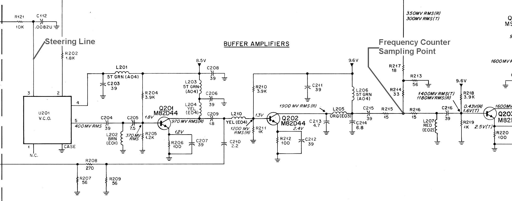
I removed the RF board and connected a wire to a point where I could pick up a strong signal to feed into my frequency counter. I also connected a wire to pin 3 of the VCO (it's steering line input). This will read the same as the test point marked SL, but since I wanted to feed a voltage INTO the VCO directly, I chose this point instead.

Click on the image for full size.
This piece of the schematic shows you where I'm picking up the VCO output signal to feed into my frequency counter.
Click on the image for full size.
I connected a variable DC power supply, a DC voltmeter, and a 3k resistor from the wire (attached to pin 3) to ground. I turned things on and read the frequency as I adjusted the voltage feeding the VCO. (The programmed frequencies don't matter; we're controlling the steering line rather than the radio.) This gave the range of the VCO's frequency based on its steering line voltage. I added a column for the receive frequency (VCO + 45.1 MHz). The results are summarized below.
| VCO Frequency Range | ||
| VCO Pin 3 |
Frequency In MHz |
|
| Volts DC | VCO | RCV |
| 1.0 | 796.2 | 841.3 |
| 2.0 | 803.9 | 849.0 |
| 3.0 | 809.9 | 855.0 |
| 4.0 | 815.3 | 860.4 |
| 5.0 | 819.6 | 864.7 |
| 6.0 | 823.9 | 869.0 |
| 7.0 | 828.0 | 873.1 |
| 8.0 | 832.0 | 877.1 |
| 9.0 | 836.0 | 881.1 |
| 10.0 | 840.0 | 885.1 |
The MaxTrac service manual says the voltage on the SL test point, which feeds pin 3 of the VCO, normally runs from 1.8 to 7.8 volts DC. As you can see from the above table, the voltage range needed to cover the 806-825 MHz band is about 2.3 to 6.2 volts. I measured 2.31 volts when the receiver was programmed to 851 MHz; this corresponds to a transmit frequency of 805.9 MHz. I measured 6.24 volts when the receiver was programmed to 870 MHz; this corresponds to a transmit frequency of 824.9 MHz. You can also see why the stock VCO on this RF board will not receive the 900 MHz amateur band; it just runs out of range. When the shift line on a talk-around VCO is high, the VCO shifts upwards approximately 45 MHz; under this condition, the receiver CAN pick up signals in the 900-930 MHz range.
Converting the VCO:
I will tell you right at the start: this is not for the faint-of-heart, nor for the die-hard Motorola aficionados. You must cut open the top cover of the VCO and add two small wires to the existing circuitry. The placement of these must be adjusted as you go. It took several minutes to make each cut, then another half hour to add the wires and get the VCO to operate in the proper frequency range. After this, I had to solder most of the cuts closed.
If you haven't already done it yet, now would be a good time to install conventional firmware, blank and initialize the board, and make sure the stock radio is working properly. Program a couple of 800 MHz frequencies and verify that the transmitter is on frequency; use the RSS service mode "warp" adjustment screen if necessary to get the transmitter dead on frequency. You won't be able to do any alignment after the VCO is converted to deal with the 900 MHz band.
If you want just a receiver (case 3 above), program one channel with 902.0 MHz and another channel with 928.0 MHz. I used RSS version R07, which lets you enter out-of-band frequencies using the shift-key method. The LAB software would work as well; you'll need that to convert the radio to conventional anyway.
If you want a transceiver (cases 2 and 4 above), program one channel with 902.0 MHz Transmit, 927.0 MHz Receive, and another channel with 903.0 MHz Transmit, 928.0 MHz receive.
Next, remove the RF board from the radio. I used a Dremel (rotary) tool following instructions by Dan, W2PUT. He recommended a 1/32-inch cutoff wheel and said the 1/64-inch wheels were too fragile. I borrowed a tool and bought a five-pack of official Dremel cutoff wheels. I must thank The Dremel Corporation for NOT showing any dimensions of the wheels contained in their packages. The ones I bought looked thin, but in this case, "looks definitely are deceiving". The Dremel 540 Cut-off Wheels (pack of 5) that I bought are definitely NOT the ones to use.
Make sure you wear the proper safety equipment when using any power tool, and observe all the manufacturer's recommendations for use. Make sure that you cut so that the metal fragments are directed away from you. This paragraph shouldn't be necessary, but the trial lawyers have proven that common sense is not common, and we thank you for reading it.
I made my four cuts but they were awfully big and messy. The wheels I bought were 0.0625 inches thick by 1.252 inches in diameter when new and the cuts came out nearly 0.095 inches wide. The metal cover on the VCO is rather thick but (fortunately) soft steel. The moral of this story is to buy cutoff wheels (also known as "rotary saws") that are paper-thin, even if they do break. (After looking on Dremel's web page, I found their p/n 409 is 0.025 inches thick and their p/n 420 is 0.040 inches thick. I'd recommend getting either one of these and working slowly. They don't show the thickness of the p/n 540 wheels.) Too much material was chewed away to make the slots in the VCO cover on my radio. Soldering them closed again took some effort. Anyway, remove the sticky foil label and make the cuts through the top cover in the sequential order shown on the photograph below.
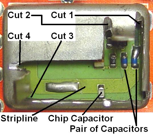
Click on the image for full size.
Cut #1 is near the right edge (as you would read the label on the VCO). Cut #2 is about 1/4 inch to the left of cut #1. Cut #3 is near the bottom edge, and cut #4 is about 1/4 inch above cut #3. The two tabs of metal can be carefully bent upwards to gain access to the circuitry inside. Dan, W2PUT, sent me a picture of his opened VCO. Note that he used a much thinner cutoff wheel than I did.
Click on the image for full size.
Now that it's open, make sure you clean all the metal filings off the RF board and from inside the VCO. Use a long brush and blow into the VCO to dislodge anything.
Adjusting for a Wide-Band Receiver (Case 3):
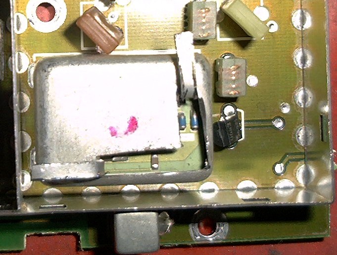
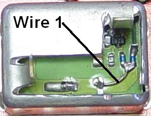
The next step is to add some inductance to the VCO. Take a one inch long piece of #22 solid wire and bend it into an arc. Add a little blob of solder to one end and attach that end to the pair of capacitors on the right side of the strip-line. Bend the wire so it follows the strip-line. Solder the left side to the top of the chip capacitor and cut it off. Now solder another piece of #22 solid wire to the top of the chip capacitor and let it hang out along cut #3, to the left of the chip capacitor. Refer to the photos above for parts identification.
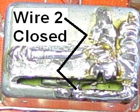
Position the wire as flat as possible on top of the etched strip-line. Bend the right cover flap back down flat and solder cut #1 and cut #2 closed. You can now put the RF board back into the radio, but keep your soldering iron hot.
Connect a DC voltmeter to the wire that you soldered to the VCO pin 3. Connect a frequency counter to the other wire that was soldered onto the bottom of the board earlier. Now apply power to the radio and turn it on. Set the radio for the channel you programmed to 902.0 MHz earlier and observe the DC voltmeter. It'll probably be around 8.7 volts, indicating the frequency needs to go higher, and the frequency counter will probably indicate around 835 MHz.
While the radio is still on, tack-solder the exposed end of wire #2 to the edge of the VCO cover at cut #3. Don't heat the wire too hot or it will unsolder itself from the chip capacitor. This will change the VCO's frequency, depending on where you position it or solder it. You're aiming for around 1.5 to 2.0 volts when the radio is trying to receive 902 MHz. Once you have it there, change to the 928.0 MHz channel and check the SL voltage. You should get something around 7.5 to 8 volts. Adjust this end of the wire until you get values between 1 and 2 volts and the frequency reads 856.9 MHz when the 902 MHz channel is selected. It should be between 7 and 8 volts and 882.9 MHz when the 928 MHz channel is selected. If you can't get the SL voltages and VCO frequencies to come within this range, you may have to unsolder wire #2 and move it just a bit to the right of the chip capacitor, then repeat this tuning procedure. Moving the end at the chip capacitor would be considered "coarse" tuning; moving the end you solder to the edge of the VCO cover is the "fine" tuning adjustment.
Adjusting for a Transceiver (Case 2 and 4):
The steps are the same as the modifications for making the radio receive 902-928 MHz, but the frequencies are different. Also, since the T/A radio will be transmitting during this procedure, connect a dummy load to the antenna jack on the PA.
We still need to add some inductance to the VCO. Take a one inch long piece of #22 solid wire and bend it into an arc. Add a little blob of solder to one end and attach that end to the pair of capacitors on the right side of the strip-line. Bend the wire so it follows the strip-line. Solder the left side to the top of the chip capacitor and cut it off. Now solder another piece of #22 solid wire to the first wire, just at the right edge of the chip capacitor and let it hang out along cut #3, right above the chip capacitor. Refer to the photos above for parts identification.
Position the first wire as flat as possible on top of the etched strip-line. Bend the right cover flap back down flat and solder cut #1 and cut #2 closed. You can now put the RF board back into the radio, but keep your soldering iron hot.
Connect a DC voltmeter to the wire that you soldered to the VCO pin 3. Connect a frequency counter to the other wire that was soldered onto the bottom of the board earlier. Now apply power to the radio and turn it on. Set the radio for the 902/927 MHz channel and observe the DC voltmeter. It'll probably be around 8.7 volts, indicating the VCO frequency needs to go higher.
While the radio is still on, tack-solder the exposed end of wire #2 to the edge of the VCO cover at cut #3. Don't heat the wire too hot or it will unsolder itself from the chip capacitor. This will change the VCO's frequency, depending on where you position it or solder it. You're aiming for around 2 volts when the radio is trying to receive 927 MHz. Once you have it there, change to the 928 MHz channel and check the SL voltage. You should get something just slightly higher. Go back to the 902/927 MHz channel and press the PTT button. Adjust the end of the wire until you get a value around 6 volts and the frequency reads 902.0 MHz when the 902 MHz channel is selected. The SL voltage should be slightly higher when the 903/928 MHz channel is selected. If you can't get the SL voltages and VCO frequencies to come within this range, you may have to unsolder wire #2 and move it just a bit more to the right of the chip capacitor, then repeat this tuning procedure. Moving the end at the chip capacitor would be considered "coarse" tuning; moving the end you solder to the edge of the VCO cover is the "fine" tuning adjustment. Keep checking that the SL voltage is low (1-2 volts) when receiving 927 or 928 MHz, and high (5-6 volts) when transmitting 902 or 903 MHz and adjust the wire until everything is stable on both channels in receive and transmit.
I just re-modified the VCO on my non-T/A RF board in preparation for moving it from case 3 to case 4. I programmed five carrier-squelch channels into a radio. Here are the frequencies and SL voltages. You should aim for voltages just a bit higher. I reached into the slot and bent wire #2 slightly and got the SL voltage up to 1.1 on 926 RX and 6.49 on 905 TX. I'm much happier with these voltages.
| Frequency and Mode |
SL Vdc |
|---|---|
| 926.0 RX | 0.89 |
| 927.0 RX | 1.00 |
| 928.0 RX | 1.11 |
| 929.0 RX | 1.23 |
| 930.0 RX | 1.35 |
| 901.0 TX | 4.67 |
| 902.0 TX | 4.95 |
| 903.0 TX | 5.23 |
| 904.0 TX | 5.52 |
| 905.0 TX | 5.81 |
Finishing the VCO Surgery:
Now, carefully bend the bottom cover flap down flat and solder cut #4 closed. This will most likely affect the tuning slightly, so move the tail end of wire #2 until you get the same SL voltages as you got earlier. As you close the flap and solder the cut, the SL voltage will probably drop, so you'll have to move the tail end of wire #2 to the right to compensate. Cut the remaining wire off after you've soldered it to the VCO cover. Don't solder cut #3 shut as it will greatly affect the tuning.
This photo shows the final VCO. You can barely see wire #2 through the slot in the cover.
The Final Steps:
Unplug the radio, remove the RF board, and remove the two wires you soldered on to the bottom of it earlier (for frequency and SL voltage monitoring). At this point, you have a radio capable of receiving 902-928 MHz with a non-T/A RF board (case 3), or a radio capable of receiving 927-928 MHz and transmitting 902-903 MHz with a T/A RF board (case 2). Follow the steps in the next section to enable the non-T/A radio transmit in the 902-903 MHz band (case 4). Continue with the steps outlined in my other article for replacing or shorting out the two front-end filters. Since you've already replaced the firmware in the radio and programmed it, those steps are already done.
Exciter Coil Modifications (Case 3 and 4):
The T/A RF board can generate power between 806 and 825 MHz, as well as between 851 and 870 MHz (T/A frequencies). The filters are wide enough to allow operation in the 902-903 MHz range just as they are.
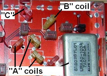
The non-T/A RF board was specifically designed to transmit in the 806-825 MHz range. The filters will not pass energy above this range unless you modify several coils by shortening them. The coils are marked in the images below:
Click on the image for full size.
This is a piece of the board layout showing the identity of the coils and their colors:
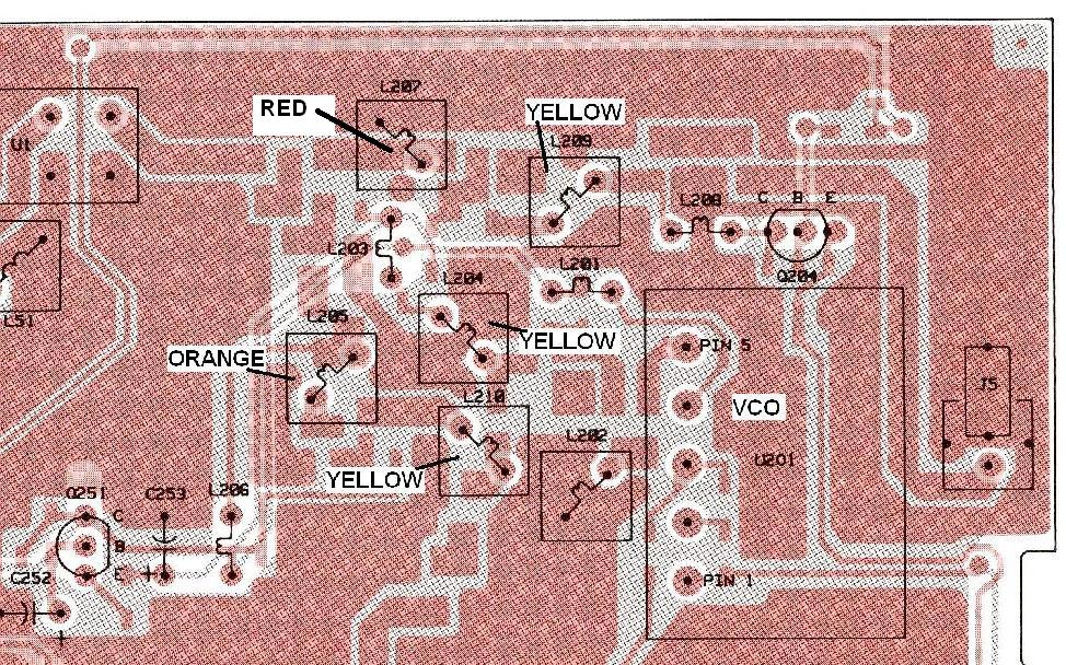
Click on the image for full size.
This is a section of the schematic so you can see which coils are being adjusted:
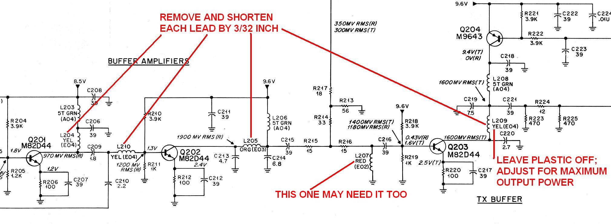
Click on the image for full size.
Do only one coil at a time so you don't put them back in the wrong places. Remove L204, L205, and L210; in the above photo, these are the "A" coils. Heat the coil wire and pull it out of the plastic cover about 1/10 inch. Shorten each leg by 3/32 inch, or about 0.1 inch. Replace L204, L205, and L210.
You might also have to do this same procedure to L207, labeled the "C" coil. This was brought to my attention by Dan after he had converted several non-T/A boards.
Remove L209; in the above photo, this the "B" coil. Heat the coil wire and remove the plastic cover entirely. Shorten both legs as above and reinstall the bare coil in the RF board.
Put the RF board back into the radio and connect a wattmeter between the radio and the dummy load. Select a transmit frequency in the 902-903 MHz range. Key the transmitter and note the power. If you aren't getting full rated power, turn the radio off; heat the leads of L209 and move it up or down just a little bit. Turn the power back on and key the radio. You are looking for the same amount of power you aligned the radio to, at the beginning of this article, which should be 15 watts or 35 watts. Keep adjusting L209 so you get full output power on both 902 MHz and 903 MHz frequencies. You may get more power than you had originally; if so, that's OK too. You can always turn it down in RSS.
Alternate Coil Modification Method:
I wrote the previous section based on information I received from Dan, who had already converted several of these radios. When I finally got around to doing my own, I felt that it was too much trouble to heat the coil wire and pull it out of the plastic body. Instead, I removed the Motorola coils and made new ones using some #22 solid hookup wire.
I made each piece about 3/4 inch long and bent them so they were the same spacing as the original coils. I let the leads hang about 1/8 inch below the circuit board, but not long enough to touch the chassis. I found it was difficult to remove the "C" coil because one lead went to a ground foil that would not heat up with my soldering iron, so I didn't bother to change that one. The top of each coil is about 1/10 inch above the circuit board, about the height (at the top) of a standard 1/2 watt carbon composition resistor body. You can gauge the height yourself by looking at one of the yellow coils you removed and making the new coils about 1/10 inch shorter, which doesn't leave much in the plastic.
After making four new coils one at a time, I reinstalled the RF board in the radio and keyed it up. I had barely any power on 901 MHz and a couple of watts on 906 MHz. I turned the radio off, heated the leads of the "B" coil, and pulled each one up about the thickness of the wire itself. I now got several watts on 901 MHz and even more on 906 MHz. I made the same adjustment to all three "A" coils and ended up with 13 watts on all of the 901-905 MHz channels I had programmed into the radio. The power supply said the radio was drawing 5 amps, which was exactly what it was drawing when I had aligned it to 14 watts on the 800 MHz frequencies. The photos below show the new coils.
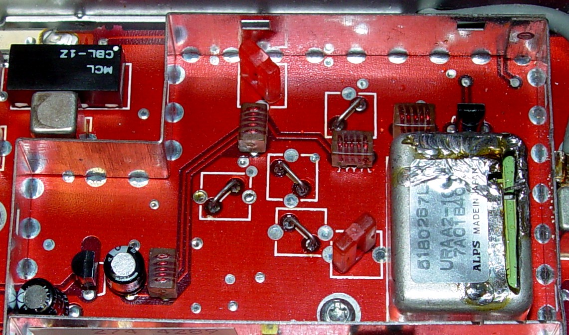
Click on the image for full size.
Here's a close-up from another angle.
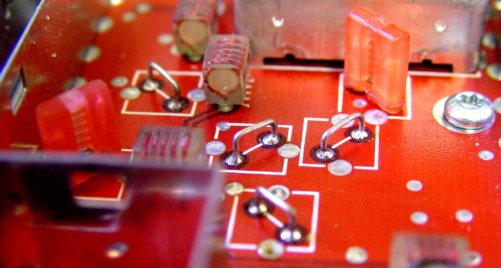
Click on the image for full size.
I didn't feel it was necessary to do any more adjusting. I can still increase the power via RSS.
Remove the RF board and re-solder the coils from underneath, if necessary.
Making the Final Adjustments:
Remember, the 900 MHz band's 25 MHz split repeaters are usually narrow deviation, 2.5 kHz wide. An 800 MHz radio is 5 kHz wide. After blanking and reinitializing the radio, the deviation will need to be adjusted. The best way to do this is to change the setting through the Alignment screens and measure the deviation, since RSS will attempt to make the radio transmit on frequencies in the 800 MHz band, and that's not possible any more. I found that my radio was deviating at 5.5 kHz with the setting at 45. I would expect to turn it down to 20 or so, to get it where it needs to be for operation on the local repeaters.
I connected the converted radio to my spectrum analyzer through a 30dB power attenuator. The power shows 12.87mW, which would be equivalent to 12.87 watts without the pad. That's close enough to the 13 watts reported by the wattmeter.
Click on the image for full size.
The spurs at +/- 3.5 MHz (I don't know where those are coming from yet) are down about 48dB below the carrier. The specification for MaxTracs is at least 55dB below the carrier for a 15w radio, so "Houston, we have a problem."

Click on the image for full size.
A 450 MHz MaxTrac and a 900 MHz GTX mobile radio didn't show anything, except the carrier, down to at least 80dB below the carrier's frequency.
Cleaning Up My Act:
I was unhappy with the spurs, so I did more investigating. I found they WERE coming from the exciter, not the PA. I also found that the number and frequency of the spurs changed if I pushed or removed the VCO area shield, and would extend to more than +/- 30 MHz away from the carrier frequency. When I removed the shield entirely, the spurs moved far from the carrier frequency. This is NOT a good thing.
I touched each of my new coils (to change the tuning) to see if that would affect the spurs; it didn't.
I tried closing the remaining cut in the VCO by bridging it with solder; this didn't help the situation either.
I tried adjusting one of my new coils slightly by heating up one end and pulling it slightly out of the circuit board, about the thickness of the wire itself. This did have a little effect on the spurs when I put the shield back on, so I tried the same trick on the rest of them. After doing this a couple of times, I lost the transmitter output signal entirely. I put each coil back where I thought it was originally but I could never get any transmit output power. Maybe I was just lucky the first time I installed the coils.
"Doctor, it hurts when I do this." "So don't do that."
Time to pull back and regroup. Since I had made my own coils, it was easy to restore the radio back to its stock condition by removing my coils and reinstalling the original ones. I also removed wire #2 in the VCO. When I programmed an 806-825 MHz frequency into the radio, it still put out 14 watts, just as it did before I modified it. At least the radio is still functioning. (Too bad it also has 915 MHz filters in it now - yes, I changed those as well. They were hard enough to put in - I'm not going to yank them out now.)
I then installed a new wire #2 in the VCO and adjusted it for 902-928 MHz receive only. I did not attempt to re-modify the exciter coils again.
Conclusion:
Dan and I had similar inconclusive results with our non-T/A boards. You can modify them to transmit in the 902-903 MHz range, but be forewarned that there is no guarantee that the emitted signal will be clean, and unless you have a spectrum analyzer available to check it, the coil conversion probably should not be attempted. I would not recommend doing it at this time. They still make great 902-928 MHz receivers once the front-end filters are replaced.
I hope the T/A radios do not exhibit this same oddity. When I obtain one, I will perform the VCO modification and verify the purity of the transmitter output before proceeding further.
Welcome to 900 MHz!
Credits and Acknowledgements:
All of the credit goes to Dan W2PUT who came up with this scheme in the first place. He encountered difficulties getting a non-talk-around radio to transmit at about the same time I did. Together we decided that these radios could still be turned into amateur band receivers. Dan also proofread this article.
Thanks go to Dave N1OFJ for proofreading this article. He has converted 900 MHz MaxTracs to the amateur band and is quite familiar with the VCOs on those radios.
Of course, Mike WA6ILQ of the Repeater-Builder web site staff deserves credit for converting the original MS Word file to clean HTML and resizing all the pictures and images to make it all look real nice.
MaxTrac, PL, DPL, GTX and a bunch more are registered trade marks of Motorola, Inc.
Circuit information for the MaxTrac radios was obtained from Motorola's official service manuals.
Contact:
The author can be contacted at: his-callsign [ at ] comcast [ dot ] net.
Maxtrac Index
Motorola index
Back to Home
Article © Copyright Novenber 2005 By Robert W. Meister WA1MIK
Artistic layout and hand-coded HTML © Copyright November 2005 and date
of last update by Mike Morris WA6ILQ.
This web site, and the information presented in and on its pages is © Copyrighted 1995 and (date of last update) by Kevin Custer W3KKC and multiple originating authors.