Up two levels (Moto index)
Back to Home
By Robert W. Meister WA1MIK

|
Up one level (MaxTrac index) Up two levels (Moto index) Back to Home |
MaxTrac 900 Trunking to Conventional Conversion By Robert W. Meister WA1MIK |
|
These are the steps required to convert a 900 MHz MaxTrac mobile radio from trunking to conventional, for amateur use.
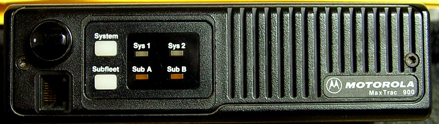
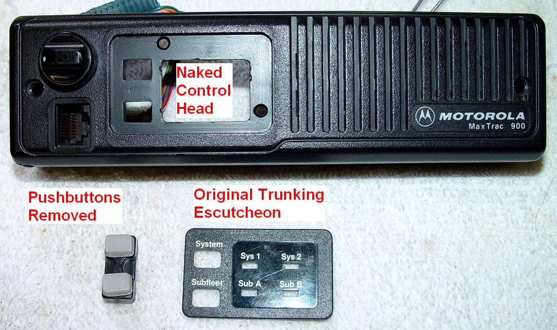
The radio was a two-channel 12-watt trunking radio, model number D27MQA5GB2AK. The front panel has two pushbuttons: System and Sub-fleet, as well as four LEDs: Sys 1, Sys 2, Sub A, Sub B. All 900 MHz MaxTracs use a logic board with a 16-pin accessory connector as well as a socketed firmware chip (PROM or EPROM). As the radio was trunking only, I did not test it for transmitter output power. Trunking radios have several test modes built-in, but the truth is, I forgot about them and I didn't feel it was necessary.
The same procedure can be used on 30-watt or multiple (6, 8, 16, 32) channel radios by choosing the proper model and panel numbers during initialization.
The mandatory steps consist of replacing the firmware, blanking the logic board, and initializing the logic board. Changing the front panel escutcheon is done merely for convenience. This entire procedure could take 30-60 minutes.
There are additional articles on this web site by Scott KBØNLY, that also go through the blanking and initialization procedure.
NOTE: If your trunked radio has sufficient conventional modes for your use, you can skip the process of replacing the firmware, blanking and initializing the radio, and just use trunking or conventional software to program the radio.
IMPORTANT NOTE: You can save yourself a lot of time and effort, especially if the radio is already working properly or you don't have the necessary test equipment to do a full initialization. Before you replace the firmware, use regular programming software, enter the Service menu, Board Replacement. Go through ALL the steps (you won't see any data on the first step - F2) and write down all the values you see for the transmit power, frequency warp, power amplifier (16 values), deviation (16 values), and all of the total deviation settings. Don't make any changes; just press F10 to exit each screen and go through each one in sequence. Then replace the firmware and blank the board. During initialization, just enter the values you wrote down in the various places as you go through the steps in sequence. You'll still have to enter the voltages, but everything else can be set where it was originally. I've developed a sheet that you can use to record these values; it can be downloaded as a PDF file here.
Replacing the Firmware:
You should try to purchase the FVN4019A conventional firmware from Motorola. Last time I ordered it, the cost was $25US, but Motorola was never able to deliver the part. After waiting several months, I canceled the order and took an erased 27C256-20 EPROM and programmed it with an image of the conventional firmware, obtained elsewhere. This is a 32kByte binary file which completely fills the EPROM. I replaced the trunking PROM with the new EPROM, by following these steps:
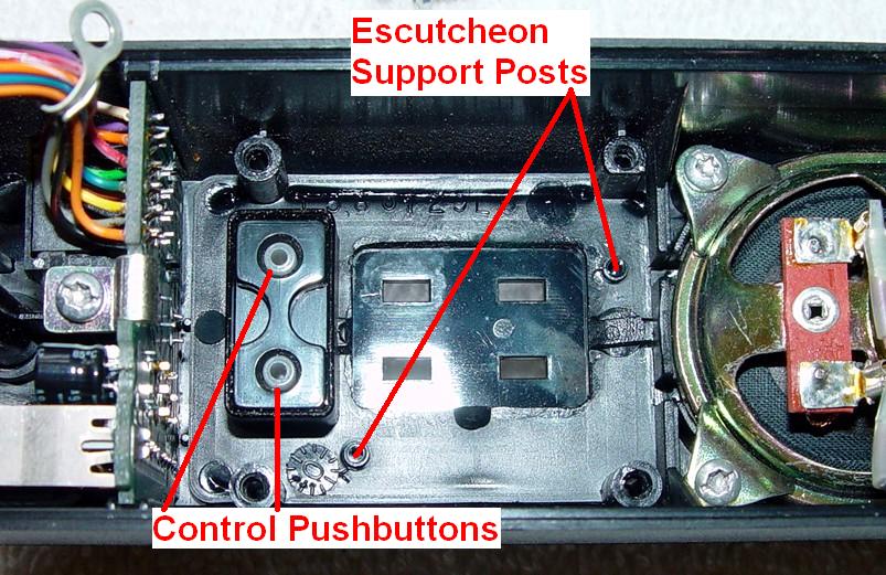
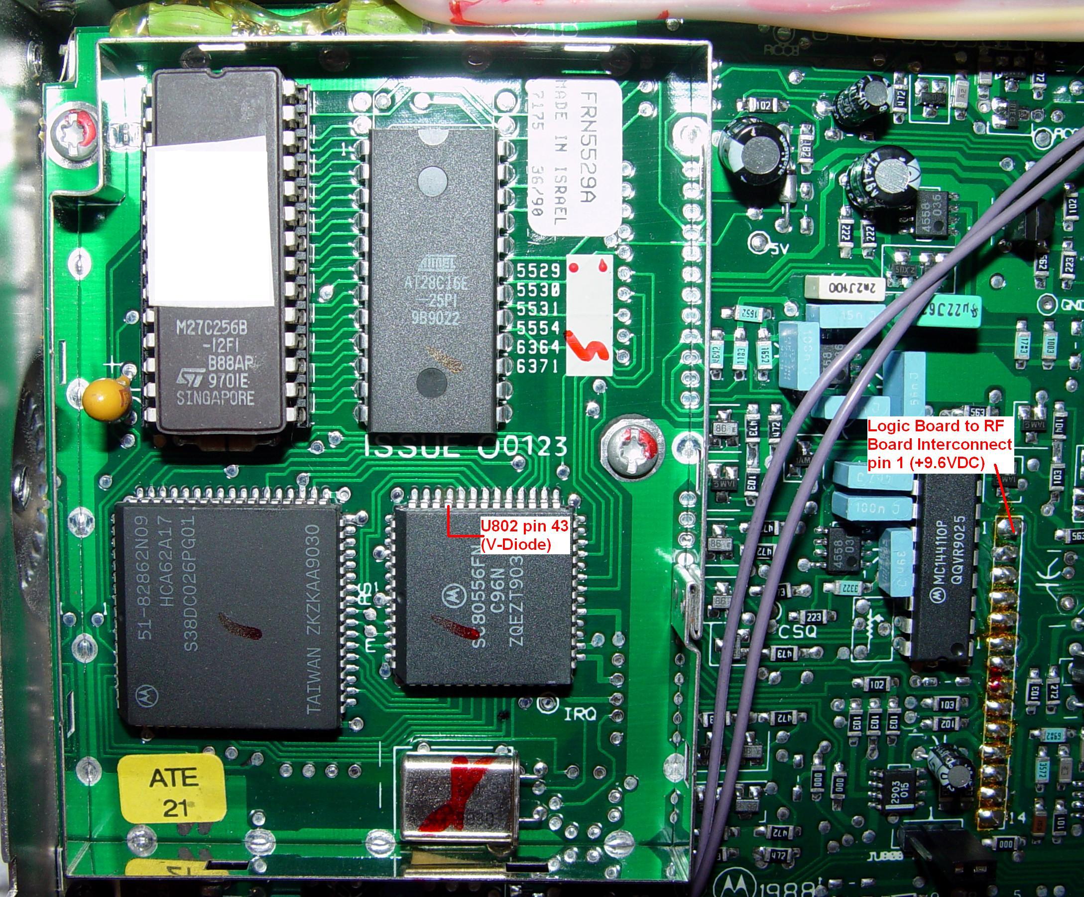
Here's what the logic board looks like:
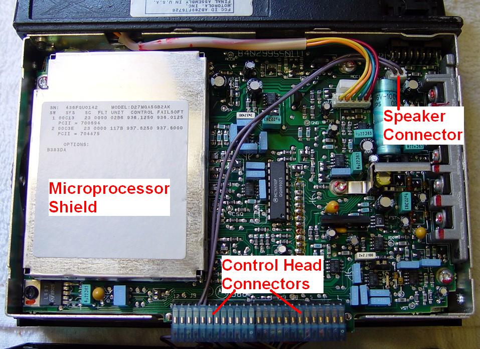
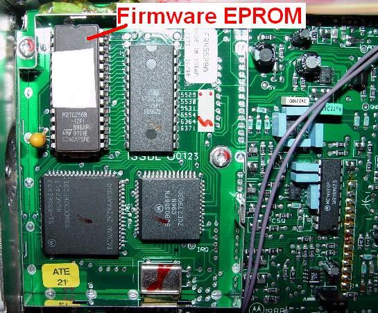
After removing the shield, here's where the firmware PROM/EPROM is. Note that pin 1 is in the upper left corner of this photo, just like the other big IC next to it. The board has "1" silk-screened on it next to the socket; you can make it out next to pin 1 of the other big IC. Installing it backwards will likely ruin the chip, as well as stop the radio from functioning (yes, it has happened).
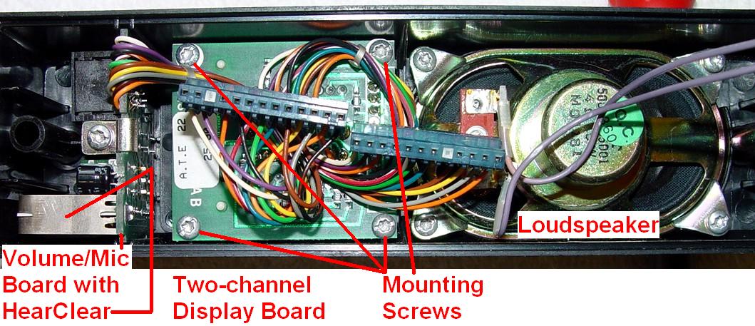
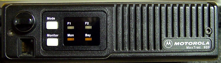
Replacing the Escutcheon:
If your radio has a conventional escutcheon already, you can skip this section. But while the radio is apart, now is a good time to change it. Refer to the photos above to identify the cables:
Blanking the Radio's Logic Board:
Connect a power cord and a programming cable, turn on the radio, the RIB, and the computer. I started MaxTrac LAB RSS and went through the following steps:
It really doesn't matter if you choose to retain the existing tuning data or not, because the tuning data is only maintained if the SAME program blanks and initializes the radio in the same programming session. In our case, we're using one program to blank the radio and another to initialize it. You could select the extended code plug, since that's what the radio will end up with, but using F3 above will take less time since only 64 code plug blocks get written to the radio. You need to blank the radio in order to initialize it as a new conventional model. Any and all code plug data (i.e. mode information) will also be cleared out by this process.
Initializing the Radio:
I connected the radio to my modulation analyzer through a 30dB, 50-watt attenuator. I applied a 1VRMS, 400 Hz audio tone to the audio input wire on the RIB. I had a digital multi-meter available for the various voltage measurements. I started regular MaxTrac RSS, and went through the following steps. User input is shown indented.
Click on this photo to see a larger, more detailed, image.
NOTES:
[1]: The two-channel radio is a MaxTrac 100. A multiple-channel radio is a MaxTrac 300.
[2]: Choose the appropriate model based on the number of channels and output power.
[3]: The two-channel radio panel number is 000. A multiple-channel radio panel number is 001.
The radio has now been completely initialized. I turned the radio off, disconnected the power cable, replaced the shield over the microprocessor on the logic board, put the plastic cover back on, and secured the control head to the front of the radio.
Program the Modes:
With regular MaxTrac RSS, I was now ready to program the two modes for the two local 900 MHz repeaters. You may desire different options and settings. Note that I used the SHIFT-NUM method to enter frequencies; if you do a lot of out-of-band programming you might want to hex-edit the MDF file accordingly. User input is shown indented.
That's it. The computer can be turned off and the RIB and test equipment can be disconnected.
Results:
The radio produced 12.0 watts on both transmit frequencies of 902.41250 MHz and 902.48750 MHz. The VCO was out of range and the receiver wouldn't hear anything unless it was unsquelched, then it heard signals on 927.41250 MHz and 927.48750 MHz just fine. HearClear WAS enabled on both channels; its effect could plainly be heard on the recovered audio.
The VCO will be opened up, carefully tuned to receive the 927-928 MHz portion of the band, and resealed. This procedure can be found in this companion article.
Equipment Utilized:
I don't own a service monitor, but I have all the separate pieces of equipment that would be contained in one. You will need to measure RF power, FM deviation, and frequency. You will need a source of audio to set the deviation, as well as an accurate digital multi-meter. Of course, you'll need a computer with the appropriate software, a RIB (Radio Interface Box), and the proper cables for your computer and the MaxTrac.
Manuals and Other Documentation:
Motorola MaxTrac 900 MHz Trunked 12 watt Service Manual, 6802977G10.
Motorola MaxTrac 900 MHz Conventional 12 watt Service Manual, 6802980G40.
Motorola MaxTrac Radio Service Software User's Guide, 6880900Z03.
Useful Part Numbers:
If you're going to do a "proper job" as the British would say, you might as well make sure all the visible parts are present, clean, and unbroken. Here are some of the parts that I keep on hand for rebuilding MaxTracs, as they're commonly damaged, worn, or missing:
| Part Description | Part Number |
|---|---|
| Two-channel conventional escutcheon | 1380276L02 |
| Multiple-channel conventional escutcheon | 1380277L01 |
| Top or bottom plastic cover | 1580127L01 |
| Small, flat-head T10 screws on sides of radio (20/pkg) | 0310943R55 |
| Volume control knob with white dot | 3680144M01 |
| DC power connector on rear heat-sink | 0980255E01 |
| Mini-UHF female antenna connector on rear heat-sink | 0980131M01 |
Note that replacing the DC power connector or antenna jack requires removal and disassembly of the power amplifier. These parts should be replaced if broken or worn to the point of non-functionality. The DC power connectors cost over $11US in 2005 and can only be purchased through Motorola.
Acknowledgements and Credits:
Thanks go to Scott KBØNLY for proofreading the article and suggesting photo opportunities.
MaxTrac, PL, DPL, HearClear, and a whole lot of other things are trademarks of Motorola, Inc.
Contact Information:
The author can be contacted at: his-callsign [ at ] comcast [ dot ] net.
Back to the top of the page
Up one level (MaxTrac index)
Up two levels (Moto index)
Back to Home
This article first posted September 2006.
Article text, photographs, and conversion to HTML © Copyright 2006
By Robert W. Meister WA1MIK.
This web page, this web site, the information presented in and on its pages and in these modifications and conversions is © Copyrighted 1995 and (date of last update) by Kevin Custer W3KKC and multiple originating authors. All Rights Reserved, including that of paper and web publication elsewhere.