Up two levels (Motorola index)
Back to Home
MaxTrac 900 MHz
VCO Frequency Range
By Robert W. Meister WA1MIK
and David W. Malicki N1OFJ
|
Up one level (Maxtrac index) Up two levels (Motorola index) Back to Home |
Extending the MaxTrac 900 MHz VCO Frequency Range By Robert W. Meister WA1MIK and David W. Malicki N1OFJ |
|
Background:
The 900 MHz MaxTrac mobile radios, like most other Motorola 900 MHz radios, transmits in the 896-902 MHz band and receives in the 935-941 MHz band. It also can transmit in the Talk-Around (T/A) band of 935-941 MHz; this is also known as Simplex or Direct.
The 900 MHz amateur band covers 902-928 MHz. Repeater operation is available with low-in, high-out at either 12 or 25 MHz offsets.
The MaxTrac 900 MHz radio's VCO (Voltage Controlled Oscillator) covers two ranges: one handles the normal transmit band of 896-902 MHz and the receive band of 935-941 MHz. It can do this because the normal receiver offset frequency in these radios is 39 MHz, i.e. the radio would normally transmit on 896 MHz and expect to receive on 935 MHz. The other VCO range lets the transmitter operate on 935-941 MHz.
NOTE: All references to left, right, top, bottom, up, or down, are when viewing the radio with the RF board facing you and the control head towards you.
Inside the VCO itself are components that control the two tuning ranges. These are often referred to as the "left VCO" and the "right VCO" because they are oriented on the left and right sides of the VCO circuit board. The "left VCO" is used for normal repeater input transmit and receive; the "right VCO" is only used for transmit on simplex channels and Talk-Around transmit operation.
To allow the radio to receive 927 MHz, the "normal" VCO range needs to be lowered a bit from 935 MHz. To allow the radio to transmit 927 MHz, the "T/A" VCO range needs to be lowered a bit as well. The modification detailed below covers the "normal" VCO only, but the same procedure can be applied to the "T/A" VCO as well.
The VCO operates at 896-902 MHz when transmitting, and in this same range when receiving the normal 935-941 MHz band. When you use the radio on the amateur band to operate a repeater, the VCO operates at 902-903 MHz when transmitting, and at 888-889 MHz when receiving 927-928 MHz. The VCO is fully capable of working at these extended frequencies once you modify it.
The Steering Line (SL) is a signal that controls the operating frequency of the VCO. A lower voltage here means the VCO is running at a lower frequency. Typical voltages are 2.0 to 7.5 volts DC. The VCO will operate with voltages outside this range, but it may be unreliable. A higher SL voltage causes the VCO to run at a higher frequency. If the VCO will not reach the programmed frequency, the SL voltage will either be below 1 volt or above 8.5 volts.
Because the VCO operates at 888 MHz when receiving 927 MHz, and at 902 MHz when transmitting 902 MHz, the SL voltage will be lower in receive than in transmit.
Some VCOs may already have the required range you need before you work on them. How can you tell? It needs to pass three tests:
If the radio passes the above tests, the VCO is working fine and you can use the radio as-is; no adjustments are necessary. One common symptom is that the radio will not open squelch or hear anything unless you press and hold the MON button to manually unsquelch the radio, at which time you will hear incoming signals. The microprocessor will normally not let the radio pass audio if the SL voltage is way out of spec.
What You'll Need:
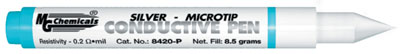
To alter the frequency range of the VCO, you must alter some internal components. This means you need access to the inside of the VCO. To do this, the soldered-on cover must be removed. Once opened, you can modify the circuit to lower the operating frequency of that particular VCO section. We use and recommend conductive ink paint. You can buy this product from various electronic parts suppliers. These come in 1/4 ounce pen-size containers that contain silver particles suspended in a lacquer base. They cost between $12 and $16. You only need a very small amount, so before you go out and spend all that money for just one radio, ask around as someone else might have it already. One such product is made by MG Chemicals:
Here's another one made by Caig Laboratories, which is also sold by Radio Shack (as part number 640-4339) for about $6US (May 2007); all the other suppliers charge $15 or more for the same 5g quantity:

Several products can be used to remove this conductive paint if you should put too much on. It really only takes a very small amount to change the operating frequency. Solvents such as acetone, alcohol, and lighter fluid will work. A commercial product called "Goof-Off" will also work; this is a mix of lighter fluid and some other chemicals. Take care when using any of these liquids, as some are highly flammable.
A soldering iron, some common hand tools, and an electric drill or drill press, with 1/16 inch and 3/32 inch bits will be needed. A digital DC voltmeter will also be required.
You'll need a version of the MaxTrac RSS that will allow you to enter out-of-band frequencies on 900 MHz. Some versions let you use the SHIFT-num method; others require you to hex-edit the MAXTRAC.MDF file. If you need to hex-edit your copy there is another article on the Maxtrac page at repeater builder that walks you through the process. Once you have a way to program your radio you should program it with at least two transmit / receive pairs so you can verify the VCO adjustment range. These can be local repeaters or 902 / 927 and 903 / 928 MHz. You should choose other frequencies if you will be adjusting the radio for something besides the 25 MHz repeater offsets. If you will also be making the radio do T/A frequencies, program some at 927 / 927 and 928 / 928 MHz.
Opening the VCO:
Remove the two T15 screws holding the control head to the radio. Remove the four T10 flat-head screws holding the covers to the radio. Remove the top cover, the RF board shield, and the VCO shield.
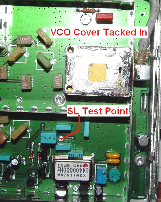
Here's a photo of the 900 MHz RF board showing the VCO and the SL (Steering Line) test point:

You should measure the DC voltage at the SL test point now, because if it's already in the 2.0 to 2.5 volt range on receive, and in the 6.5 to 7.5 volt range in normal transmit, you won't have to play with it. Similarly, if the voltage is already where it should be on T/A frequencies, you're done. On one radio we modified, the final SL voltage was 1.8 on receive and 6.2 on transmit for a 927.4125 / 902.4125 MHz repeater pair.
To open the VCO, you can either heat the top cover enough to melt the solder and try to pry it off, or peel it back without heating it up. We chose the peel method.
DANGER, DANGER, WILL ROBINSON ! !
We cannot stress this enough: be extremely careful when drilling the holes into the VCO. Go only far enough to cut through the top cover and just the top cover. GO VERY SLOWLY ! Take your time. It's better to take twice as long than to say "oops!"
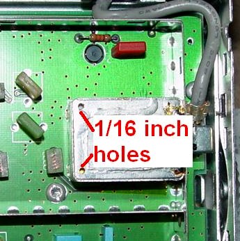
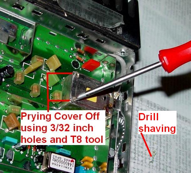
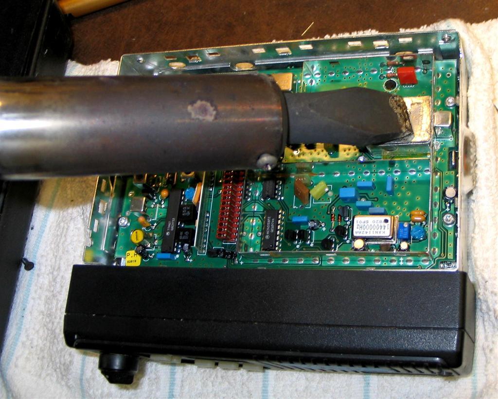
Drill two 1/16 inch holes in the two left corners of the VCO cover, about 1/16 of an inch away from the corners. Be very careful. Use a slow drill speed of around 200 RPM or less. If you're using a hand-held drill, don't let the bit go into the VCO more than 1/8 inch or it will destroy the components inside. YOU MUST GO VERY SLOWLY. You don't want metal chips inside the VCO so use a new, sharp drill bit (if you need to then go buy a new one before you start this mod) so the metal is shaved off and rises up the flutes of the drill as a long spiral. Look at the tabletop under the red screwdriver handle in the second photo below. Go slower as you proceed. Don't push down too much. When the drill has gone all the way through the top cover, you don't want to keep pushing it down. If you have or can borrow the use of a drill press for this step, use it as you have better vertical control.
After drilling these pilot holes, use a 3/32 inch drill and make the two holes a bit bigger. Remember, the drill will drop through the hole once it gets big enough, so restrain it any way you can. The larger holes allow other tools to fit in so you can start the peeling process.
We used a T8 Torx tool, but a small screwdriver, dental pick, or even an Allen wrench of the proper size would work. Insert the tool into the hole you just drilled and start prying the corner up, breaking the solder joint as you go. Do this in each corner. You can straighten the cover with a pair of pliers (or a vise) later.
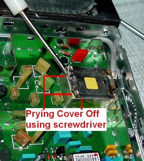
Slip a thin screwdriver or pocket knife under the raised edge and continue to separate the top cover from the sides of the VCO enclosure. Don't insert the tool into the guts of the VCO, or use any components as a fulcrum. Pretend you're opening a pop-top can, the ones where the entire lid comes off (like pet food or soup).
You can completely remove the VCO cover now. Straighten out the bent corners and try to get the cover perfectly flat. Remove any obviously loose bits of solder on the inside of the cover.
Turn the radio over and slap it on the bottom to get rid of all the metal chips from the drilling operation. If necessary, use compressed air or a small brush to dislodge anything from inside the VCO shield and on the RF board. Any remaining metal could damage the radio.
If you own a big soldering iron or gun (I used a 250w/350w Weller gun), you can also get the VCO cover off by heating the entire perimeter joint and using a thin knife blade to get under the edge of the cover. It sits inside the lip of the surrounding VCO assembly, so you need to dig down vertically at first, then as you get the blade into the gap, start rotating the blade to pry the cover up. Keep moving the heat source around the perimeter as you do this and after a minute or so you'll get the knife blade under the VCO cover. From that point you can pry it up and off. Clean off any residual solder flakes that may be sticking up on the VCO case.
Mark KD6WLY removed the top cover of his VCO a slightly different way, with a huge 250-watt American Beauty soldering iron! He provided this photo some time ago.
Modifying the VCO Range:
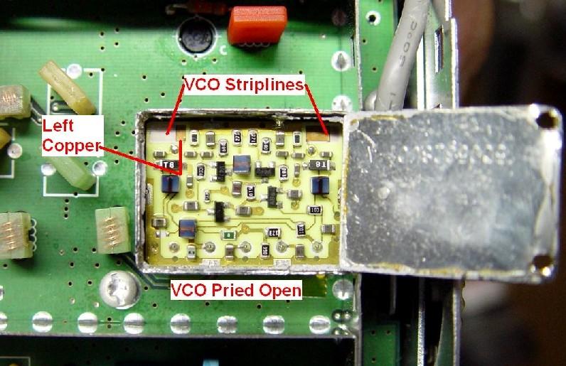
In the photo above, you will notice two copper strips in the upper left and upper right corners of the VCO circuit board. These are the laser-trimmed strip-lines. If you add some metal to the copper, by using a conductive pen, the frequency range will be lowered. We suspect that there's another piece of copper under the ceramic; the trimmed piece you can see is one plate of a very small capacitor. The plate on this side is grounded via the nearby soldered terminal stud. All you have to do is slightly extend the trimmed strip-line towards the outside edge of the VCO. This will increase the surface area of the plate on this side, which will increase the capacitance value, which will result in a lower oscillating frequency range.
The copper-colored metal at the right side of the left strip-line is the active part of the component. To the left of this is a lighter area where the copper has been removed by the manufacturer. Using a knife blade, scrape the conformal coating off the left edge of the copper so the conductive pen or solder can adhere to the it.
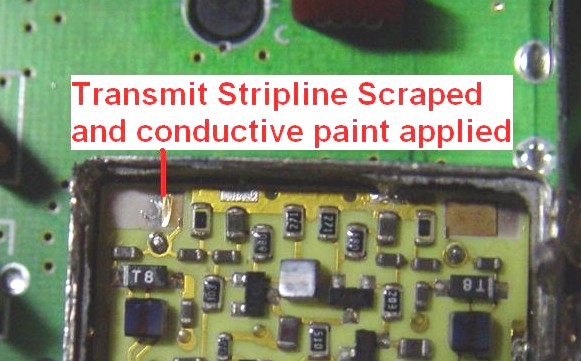
Apply a very small amount of conductive ink - about the size of a pin-head - to the left edge of the freshly cleaned copper, so it starts to fill in the area where the copper had been previously removed. You can barely see how little it takes on the upper left strip-line in the photo belowAdding ink to the area that doesn't have any copper on it will increase the capacitance value and lower the frequency. Adding ink to the copper foil area merely serves to connect the ink to the copper; a build-up here won't affect the capacitance value but you need to make a connection to the copper foil.
Connect the radio to a dummy load and power supply. Turn the radio on and measure the SL voltage in receive and transmit. The radio might not transmit at this step. One radio we modified produced 1.1 volts in receive and 5.5 volts in transmit, and it would not hear signals. You want to aim for about 2.0 to 2.5 volts DC in receive, and 6.5 to 7.5 volts DC in transmit. If the voltage is too high in receive, it means you've added too much conductive ink; the VCO frequency is now lower than it should be, and the SL voltage is trying to raise it. Use a Q-Tip and some solvent to remove some ink and measure it again. If the voltage is too low in receive, you need to add a bit more conductive ink. This is a trial-and-error procedure, but once you do one, you'll realize how little ink you really need to apply.
Use the solvent sparingly. Don't let the ink or solvent run off the edge of the ceramic circuit board; it can dry underneath and cause problems later on.
It takes several minutes for the conductive ink to dry; it's a lot easier to remove while it's still wet. Chances are you'll put on way too much the first time and have to take most of it off. "A Little Dab'll Do Ya" and it has quite an effect on the operating frequency. You can do all this adjusting while the radio is powered up, so you'll be able to see changes immediately. You may find it easier to solder a short piece of wire to the SL test point and connect the voltmeter to it with a clip lead, rather than holding the test probe there all the time.
Keep checking the SL voltage range as the conductive ink dries, to make sure you've added enough. Check all programmed frequencies to make sure the SL voltage stays within the proper range at the lowest receive frequency and highest transmit frequency.
You can repeat this procedure on the right half of the VCO if you programmed some talk-around frequencies in the radio earlier. As this section is only used for transmitting, you need to adjust the amount of conductive ink so the SL voltage is in the 2 to 7 volt range in transmit.
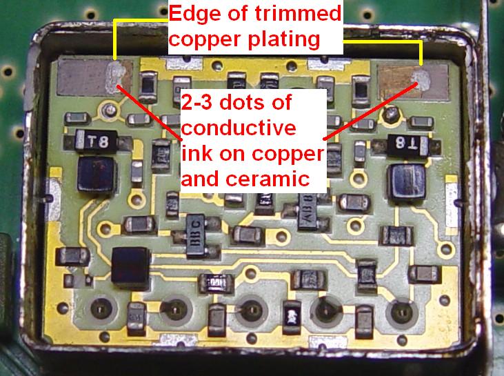
I performed this procedure on another radio that would transmit in the 902-903 MHz range but would neither receive nor transmit in the 927-928 MHz range. The SL voltage was down at 1.4 volts. Three small dots of conductive ink on the left VCO and two small dots on the right VCO brought it up very nicely. The SL voltage is now 2.3 volts on receive, 7 volts on transmit, and 2.8 volts on talk-around. A photo of the finished VCO is shown below.
Closing The VCO:
Place the VCO cover back into the shield and solder it back in place. Add very little solder; 1/4 inch per edge will be enough. Use the solder to "wet" the joint between the soldering iron and the VCO shield. You do not want to add too much because it will run down inside the VCO shield and short out the internal components; then you'll have to remove the cover, get rid of the excess solder, and start over. Remember: all of the original solder is still inside the edge of the VCO shield. Use just enough new solder to completely seal the openings. Don't worry about the two holes you drilled; they can stay open.
It's very important that the cover be soldered completely on all sides and corners (i.e. mechanically tight). Any gaps will allow the cover to flex if the radio is subject to vibration or a loud sound from the loudspeaker. This flexing will affect the frequency of the VCO, which can set up a microphonic situation resulting in noises, squeals, and howls. The photo below shows the completed modification:
Check the SL voltage after the job is complete. As the VCO will be rather hot, the SL voltage will start out a lot higher than it should be. After several minutes, it should come back down to the range you set it to when it was open. We found that the SL voltage of the closed VCO was about 0.1 volts higher than when it was open.
When we finished, the SL voltage was 2.4 on receive and 6.9 on transmit for our 927.4125 / 902.4125 MHz repeater pair.
Reinstall the VCO and RF board shields, outer cover, and control head.
This procedure took us about an hour from start to finish. This was Bob's first experience doing this modification, and he asked a lot of questions and took a lot of pictures and notes while we did it. A second radio took only ten minutes.
Acknowledgements and Credits:
Dave N1OFJ did the actual modifications while Bob asked questions, took the photos, and took notes from which this article was written. Dave proofread the draft writeup and this final article, of course.
We thank Kit N1MCC for letting us perform surgery on his 900 MHz MaxTrac. It was a very non-complaining patient. It didn't even ask for Novocain.
Thanks always go to Mike WA6ILQ of the Repeater-Builder web site staff for doing his conversion and preparation of this article.
Contact Information:
Bob can be contacted at: his-callsign [ at ] comcast [ dot ] net.
Dave can be contacted at: his-callsign [ at ] hotmail [ dot ] com.
Back to the top of the page
Up one level (Maxtrac index)
Up two levels (Motorola index)
Back to Home
This article was conceived in March 2006.
Article text © Copyright 2006 Robert W. Meister WA1MIK and David W. Malicki N1OFJ.
Artistic layout and hand-coded HTML © Copyright 2006 and date of last update by Mike
Morris WA6ILQ.
All rights are reserved by the author, including that of paper and web publication elsewhere.
This web page, this web site, and the information presented in and on its pages is © Copyrighted 1995 and (date of last update) by Kevin Custer W3KKC and multiple originating authors.