Motorola index
Back to Home
By Scott Lichtsinn KBØNLY
Edited by Scott Lichtsinn KBØNLY
Screen shots and other contributions from Robert W. Meister WA1MIK

|
MaxTrac index Motorola index Back to Home |
Converting a Two, Six or Eight Channel MaxTrac or Radius M100
to 16 or 32 Channels By Scott Lichtsinn KBØNLY Edited by Scott Lichtsinn KBØNLY Screen shots and other contributions from Robert W. Meister WA1MIK |
|
Before you even attempt this upgrade you need to take stock of what you have. Do you have a known working radio? Does it have a 16-pin (sometimes called the "expanded" logic board) or a 5-pin minimal logic board? Look at the connector on the back of the radio near the antenna connection: If it's a 16-pin board the only problem you might encounter is outdated firmware, which I will discuss momentarily. If it's a 5-pin board you really need to open up the radio and determine which logic board you have: there were three 5-pin boards and the one 16-pin board:
The preferred boards are the HLN9313A (or B) which are the only factory board with a 16 pin connector, or the HLN5172A; either is fully capable of supporting 32 channels. The other two 5-pin boards can still be upgraded to 16 channels, though the HLN5173 wouldn't until I put the newer firmware revision in.
If you have a 16-pin board and no speaker audio...

An external jumper is required between pins 15 and 16 to enable the internal speaker. On some radios I have found the plug missing, but a solder blob on the back side of the board bridging the two pins. If you are going to be running a MaxTrac as a mobile, with the only need for a accessory plug to be the speaker jumper then the solder blob makes perfect sense.
Also, which front panel do you have? If you have a two channel front panel you can't do anything until you have a full feature front panel. You can purchase a complete new front panel from Motorola for about $35 and its part number is HCN3217B. It comes minus the escutcheon; that's the flat plate that surrounds the buttons and labels their functions. Or you can scavenge one from an 800 MHz MaxTrac, which are common and cheap, and install a new escutcheon so the buttons are labeled properly. Also, six channel radios commonly have the scan button labeled as Exit, so if you want a new full feature escutcheon its part number is 1380277L01, for US$4.24 (at the time of this writing).
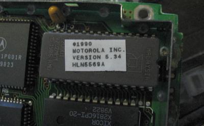
That brings us to the MaxTrac firmware. You need version 5.34 to be able to support 32 channels. Most of the 16-pin logic boards will have this, but not all! And if you take a logic board from a cheap 800 MHz MaxTrac its most likely going to have a trunking firmware EPROM, so you will need a replacement for that as well. The latest version of the firmware for the MaxTrac low-band, high band or UHF radio is available from Motorola, part number HLN5569A, cost is about $25 as of the date of this article.
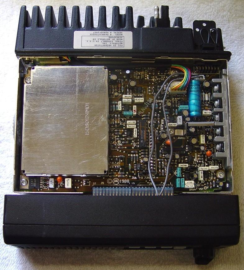
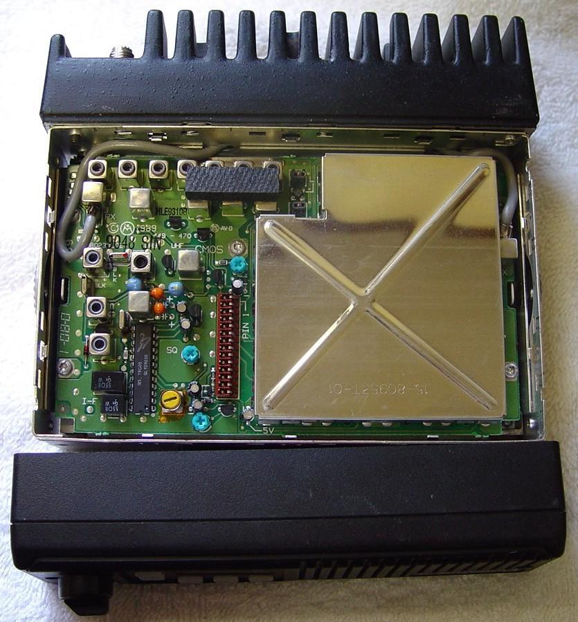
To find out which firmware you have just pop the covers off the radio, which is accomplished by removing the two screws on each side and then the two screws holding on the front panel. Removing the top cover exposes the RF board (watch out that a little white sticker doesn't fall out - see the third photo down). Removing the bottom cover exposes the logic board.
Once the radio is upside down on the bench (logic board up) look for a small shield. Pry off that shield carefully working your way around it to loosen it.
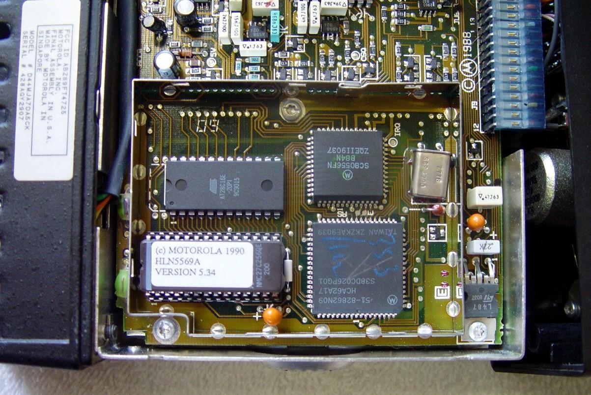
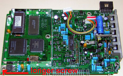
Once the shield is removed you will see a 27C256 eprom in a socket (the top right one with the blue and white label in the picture). This is the firmware - the program that runs the entire radio. It will be labeled on top with the firmware revision number. If you have a logic board from an 800 MHz radio it may be a trunking PROM, which is totally useless (unless it has a round window in the top of the chip, which means it can be erased and reprogrammed). If you do not have a version 5.34 chip, then stop here and get a replacement before continuing. Motorola will be happy to sell it to you, or again, the PROM image file is out there, but don't ask the author, the editor or repeater-builder.com to provide it.
At this point I'm going to assume that you have a working radio, a logic board with version 5.34 firmware and a full feature front panel, an old, slow computer, a RIB and the correct RSS.
First, swap your two channel front panel with your full feature one if necessary and don't worry about its odd behavior when you power it up. For one, the display will not function correctly as the logic board still thinks that it's a two channel front panel.
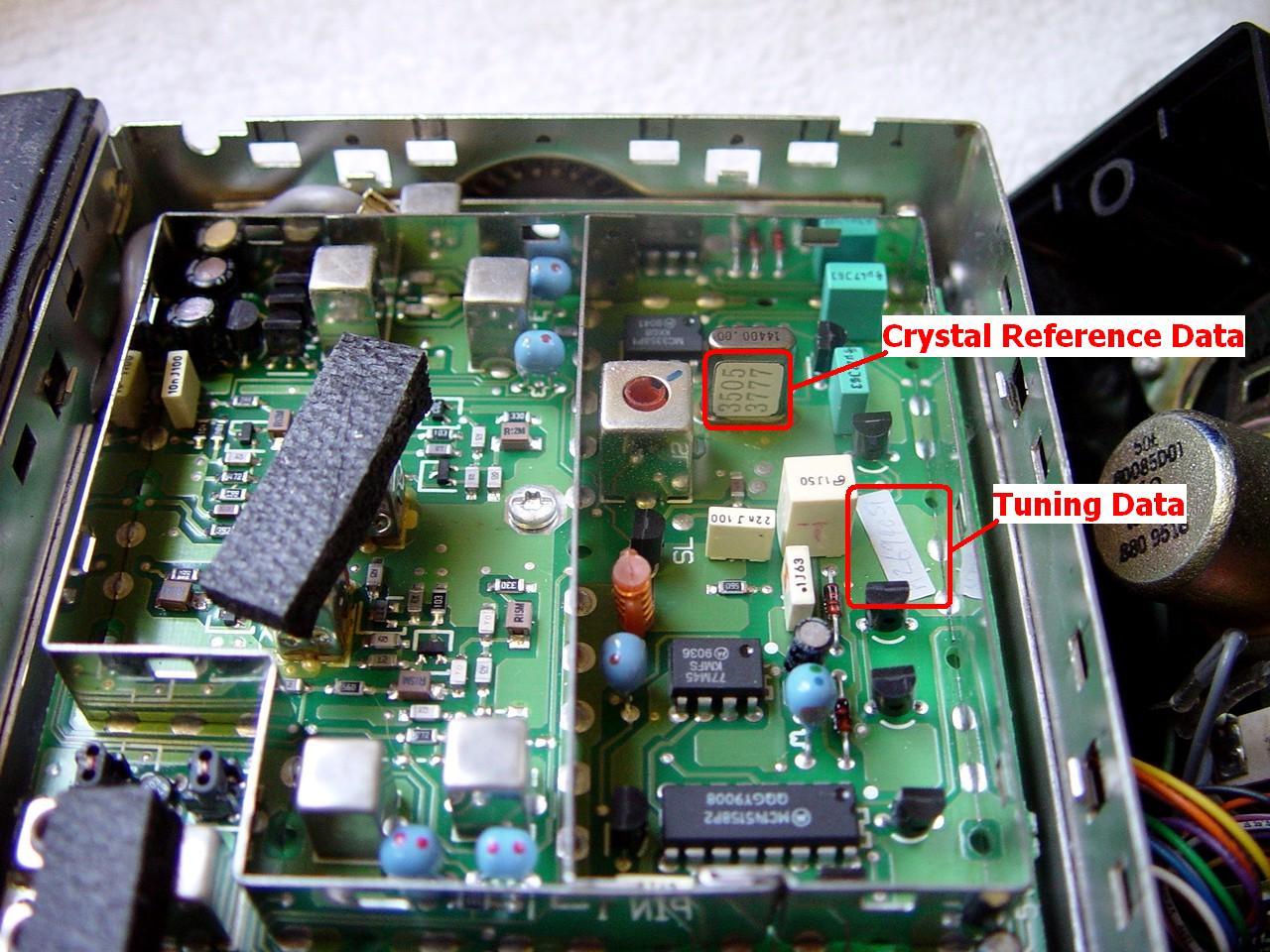
Next, open up the radio, if you haven't already done this in the step above to verify your firmware revision. While removing the top cover watch for a white sticker to be loose inside. Sometimes they fall off with age and are just lying loose inside the radio. See the note later on regarding the tuning data sticker and the ramifications if it is missing.... You might want to copy the number to the inside of the circuit board RF shield with a Sharpie pen...
The existing logic board has all the settings and tuning information from the current radio. The replacement logic board has to match, so in the next step you need to record three numbers plus all the tuning information from the old board so it can be written into the new one:

Now you need to connect the radio to a dummy load (just as a safety precaution), and the RIB / computer. If you have a 16-pin logic board, make sure to install a jumper on the internal speaker pins (there is no other way to get speaker audio, short of adding a solder blob jumper on the foil side of the logic board) and a second one on the alarm pins. Then power everything up. Now use the RSS to read the radio to obtain all the other important information.
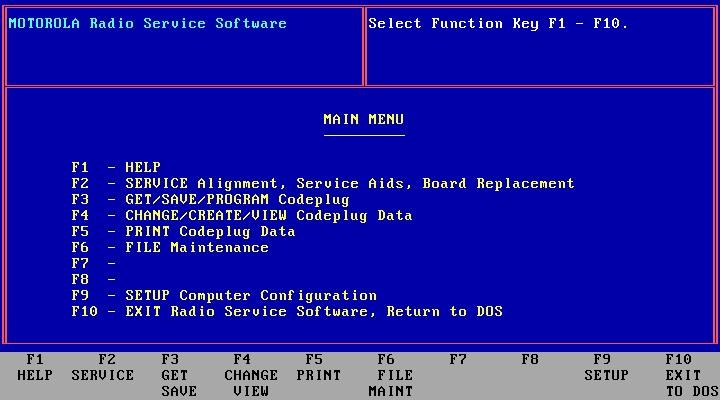
Hit F2 to enter the Service menu.
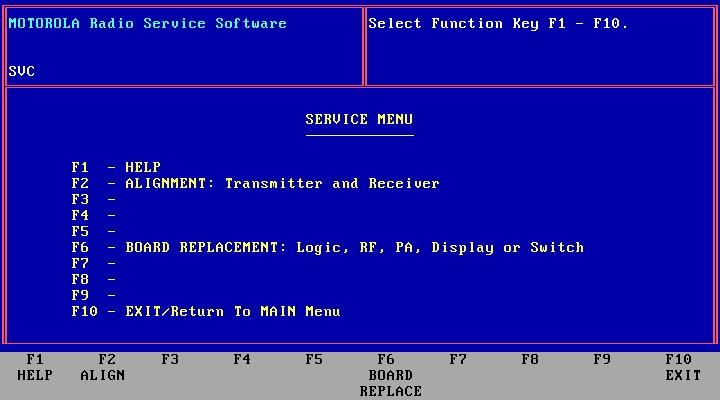
Hit F6 to get to the Board Replacement window.
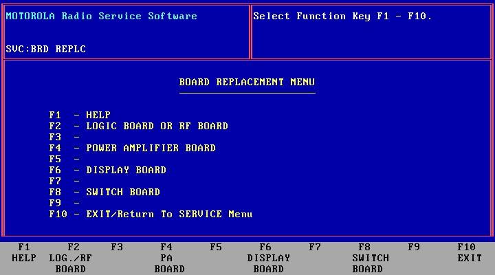
Hit F2 for the Logic or RF Board.
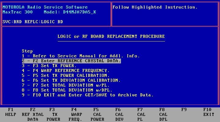
Now, what you want to do is select each one of these steps, one at a time, and print or write down the info displayed on each page. Having a printer hooked to your RSS computer allows you to save time by doing a "Print Screen" on each one.
Note from WA1MIK:
I've had to do this a number of times and do not have a handy printer to hook up to my programming computer. So I designed an alignment data sheet (PDF file) that you can download and fill out as you read the various alignment screens. It has provisions for the crystal/tuning data and 9.6V reading. It can also be used on 900 MHz radios. Click here to download the file.
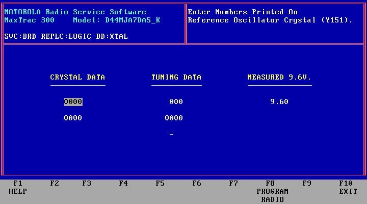
You can skip F2 because that is the info you recorded from the labels inside the radio and on an initialized board it will be all zeros anyway.
Hit F10 to return to the menu, then F3 to go to the next step, when you get to each screen you need to print the screen or accurately record everything on each screen. When you are done with each screen just hit F10 to return to the menu.
Here's the F3 screen:

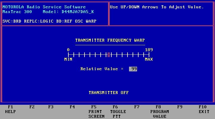
The F4 screen:
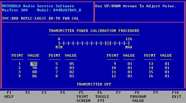
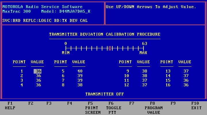
The F5 screen:
The F6 screen:
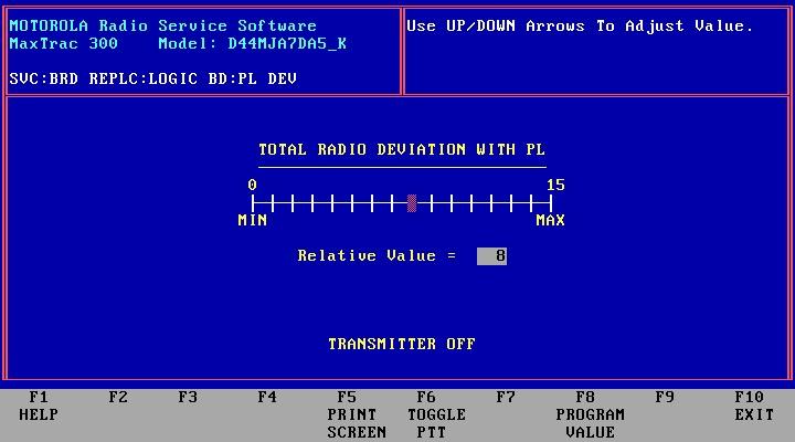
The F7 screen:
The F8 screen:

What you are recording is the current alignment data for the radio, which you need to type back in when you reinitialize the radio as a 16 or 32 channel unit. If you are going to be using a logic board from another radio to replace yours you will need to also use these numbers as a starting point for the new values on the new board. Further info on these procedures will be coming up in nother article focusing solely on Logic Board replacement. Note that if you swap logic boards that they are held in by six screws, with one longer than the other five. That longer screw always goes into the corner that is on the opposite diagonal corner from the accessory connector (no matter if it is 16 pins or 5 pins).
Now while you also have the radio connected you might as well read the full codeplug in its current form and save it for future reference in case the worse happens! Just hit F10 until you are back at the main menu:
Then hit F3.
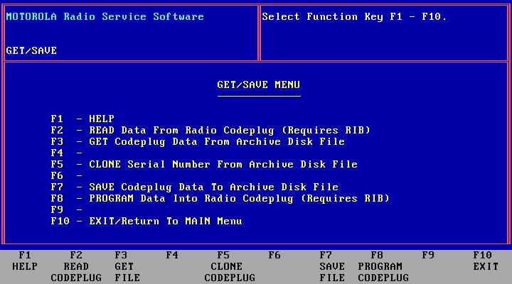
Then hit F2 to read the radio. Once it's done reading it will return to the Get/Save Menu, now you can save the read data by hitting F7.
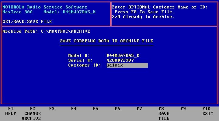
It will ask for a customer id, and above if you haven't already set the location of your archive you will need to input the directory you wish to save into. Just put in your name, call sign, whatever you prefer for Customer ID. Then hit F8 to save the file.
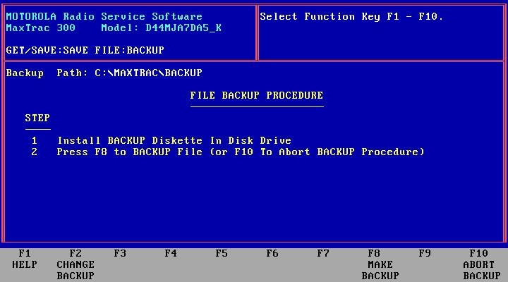
After its done saving it will then ask if you want to make a backup. That's entirely up to you! If you do make a backup floppy make sure to store it in a safe place. This backup will be the exact same as the saved codeplug on the hard drive.
Now its time to use MaxTrac Lab. Run the software, the radio still being on and connected to the computer and the RIB, of course.
![]()
From the main menu select F2, the Service menu:
![]()
Then select F8 to "Blank" the board:
![]()
Then select F8 "Blank Board with Extended Codeplug, Clear Tune Data".
Note from WA1MIK:
You can actually select Extended or Normal codeplug; during board initialization the proper size codeplug will be written to the radio based on the model and features you select, regardless of what you choose here. Normal is faster as it writes out less data. You can also choose to Save or Clear tune data as you'll be putting the original tuning data (that you saved above) back in shortly.
Make sure you do not interrupt this procedure. It will wipe the entire logic board then exit back to the menu. You may now shut down the MaxTrac Lab, and once again run the regular MaxTrac RSS. This is important; you want to reinitialize with the standard MaxTrac RSS, not the Lab version.
Note from WA1MIK:
When the blanking process is complete, the radio will emit a long boooooop and the front panel LEDs on a 6/8/16/32 channel radio will go out. Do not panic; this will be straightened out shortly.
Select F2 for the Service menu, then F6 Logic Board Replacement, then F2 for the Logic Board. Now, with a blank board you are allowed to set the parameters of the radio. You will only see this screen with a blank board while entering the logic board replacement procedure. If the board is not blank you will just see the normal screen with F2-F9 listed:
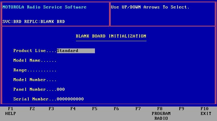
Make sure for product line you select "Max High Sig" if you're doing a 16-pin logic board and you want full features and 32 channels, or if you're doing the full feature 5-pin board as discussed above. Then set the Model Name to "MaxTrac 300", set the the range according to the radio's RF board. You can not change a radio's operating band or range just by selecting something it is not, so make sure you set it to what the radio really is (i.e. what the RF board installed in the radio actually is).
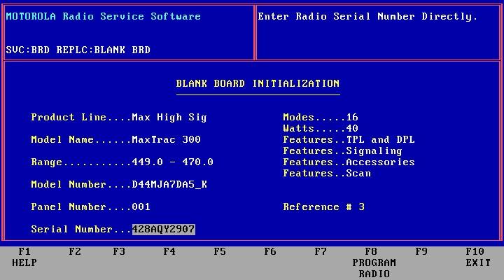
For the Model number field use the up and down arrows to scroll through the list showing the radio options based on the model number selected. Scroll through them and watch the number of channels and power level, make sure if you have a 25w radio it shows 25w, and if it's a 40w it has to show 40 watts... If you pick the wrong numbers all the soft pot values in the alignment will be way off, and this is not a good thing. In the screen shot picture you can see an example of me initializing a 16 channel UHF radio (note: on a conventional i.e. non-trunked radio, "Modes" are the same as "channels"), and since this particular radio is a 40w radio, the power is set to match. All the features are shown, making it a full feature radio. If you're making a 32 channel radio just do everything the same, just select an appropriate 32 channel model number with the correct power level.
For the "panel number", set it to "001" for anything except the two channel front panel (for it, use "000"). In most cases this procedure will be used to create a 16 or 32 channel full featured radio, but in case you are putting together a radio from spare parts the same procedure applies to a two channel radio, just make sure to set it to "000" for the two channel front panel. Then input the serial number from the label on the radio. And double or triple check everything on this screen before hitting F8 to program the radio! If you make a mistake on this screen you will be blanking and initializing the radio all over again.
When it's done programming a couple beeps will be heard, and if you swapped from a two channel head to a full feature head you will now see everything light up. Then you will be returned to the service menu, press F6 again to get back to the Board Replacement menu, then F2 to the Logic Board menu.
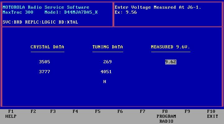
Now you get to go through one screen at a time (just as you did above to view and record all the tuning information) and re-enter all the tuning information you recorded earlier and program each parameter one by one. Be careful! If you make a mistake you have to complete all the screens that follow before it will let you start over again! So double check each screen before programming! Here's the crystal/tuning data screen filled in:
Once you are done re-entering all the tuning data just hit F10 until you are back to the main menu, from this point on its just like programming a MaxTrac on a normal daily basis... you hit F4 "Change Create View", and then you can change all the radio options, radio wide options like PL tones and accessory connector options. And also the individual channel data, RX and TX frequencies for each. Make sure that if you don't have the emergency switch jumper on the 16-pin accessory plug that you set the emergency switch option to "Null" in the RSS options screen (otherwise you get the error boop sound on power up, which sounds like, beep boop). Shut off any of the accessory options that you don't plan on using to avoid problems. To get to this screen hit F4 "Change", then F2 "Radio Wide", then F9 as shown towards the bottom right as other accessory.
On this screen you can also set for PL, DPL and CSQ detect, or just CSQ detect for an output to satisfy the needs of a repeater controller input when using the MaxTrac as a receiver for a repeater, a link, or a remote base (see the "MaxTrac Repeater Interfacing" article for more details).
Note that some options interact: If you are using the talkback scan feature you need to make sure that the "busy channel lockout" option is OFF (on a per channel basis).
When everything is set properly you can program the codeplug and you're done. To do this go back to the main menu after you have set everything the way you want it and hit F3 "Get Save Program", and then F8 "Program". It will ask if you are sure, hit it again and it will program. You might also want to save the codeplug to disk by hitting F7 on this screen first, then programming the radio. This way you always have a codeplug saved in case the radio gets corrupted, and you can also make changes without the radio by loading the saved codeplug and making your changes before connecting to the radio. This is really nice when the radio is permanently mounted in a mobile install, as you can make the changes from the comfort of the work bench then go connect to the radio and upload the program to the radio.
That's it, you have a full feature radio with either 32 or 16 channels, depending on which logic board you were working with. If it's a UHF radio and you are now interested in using it in the UHF ham band just look for the "Moving a 449-470 MHz MaxTrac" article. It explains how to retune the VCO down to push it down to 440 MHz, and how to adjust TX power out below 450 MHz.
If the tuning number / board number sticker is missing from the
RF board...
First, note that it is on the RF board, not the logic board. But, if you
have opened up a radio and the sticker is missing from the RF board (the
board under the top cover of the radio), then you are in trouble. The
only way to get that number is to do a full - from scratch - factory
alignment (which requires the book). Motorola should have made it so this
information gets stored in a viewable location of the codeplug (like the
"customer ID"), but when you go to the logic board replacement screen the
F2 crystal reference data always comes up as all zeros. Which is why they
put the label on the crystal and a second one on the board. I haven't yet
seen a missing label on the crystal, mainly because the wax or whatever
substance they use to dampen it around the base usually spreads onto the
sticker a bit and helps hold it on.
If the 7 digit tuning/board number sticker is missing from a radio you could use a number from another radio of the same band and power output to get you close enough to fine tune everything. But the best way is to do a full factory alignment.
And then write the number onto the inside of the radio with a Sharpie pen - and not on the underside of the cover! I was doing that until one day I had two radios open on the bench, finished what I was doing, and caught myself putting the wrong cover back on the radio...
Contact Information:
The author can be contacted at: kb0nly [ at ] mchsi [ dot ] com.
Article by Scott D. Lichtsinn KBØNLY, January 2005.
Screen shots, new photos, new formatting, and MaxTrac Alignment sheet by Robert
W. Meister WA1MIK, December 2006.
Back to the top of the page
Maxtrac Index
Motorola Index
Back to Home
This page was originally posted in January 2005.
Article text copyright © 2005 by Scott D. Lichtsinn KBØNLY.
Screen shots, clear photos, MaxTrac Alignment sheet, and new layout ©
Copyright 2006 Robert W. Meister WA1MIK.
This web page, this web site, the information presented in and on its pages and in these modifications and conversions is © Copyrighted 1995 and (date of last update) by Kevin Custer W3KKC and multiple originating authors. All Rights Reserved, including that of paper and web publication elsewhere.